Evaluating the Functional Performance of
Small-Scale Public Demountable Buildings
Thesis submitted in accordance with the requirements of the University of Liverpool for the degree of Doctor of Philosophy by:
Junjie Xi
iii
Abstract
This thesis investigates the design, operation and use of contemporary demountable buildings, and explores how functional performance can be assessed in small-scale examples for public use alongside with their relationship to other design elements. The research focuses on three case studies that do not require a high-technology building environment or complex construction skills. Demountable buildings are defined as those that are transported in a number of parts for assembly on site. Contemporary demountable buildings respond to ecological issues, social impacts, technological innovation and economic demands. They can be used to measure a society’s development in environmental sustainability, innovation and economic growth through various forms. Small-scale demountable buildings fulfil many temporary habitation needs in diverse roles, such as non-emergency transitional housing, ephemeral exhibition buildings and seasonal entertainment facilities.
The purpose of examining functional performance is to assess if, and how, the requirements of the design have been achieved. This enables project operators to address functional performance from a public perspective by reflecting on the scope and ambition of their projects. This thesis draws on existing literature to investigate previous and on-going research relating to demountable buildings, including classification, the construction process and project management. It also examines selected existing evaluation methods that cover principles, modelling and computer-based solutions from a wider research area, including Guidelines Developed by City Council and Culture Sectors; Assessment Methods in Humanitarian Response and Methods in Environmental Assessment.
v
Content
Abstract ... iii
List of Tables ... ix
List of Illustrations ... xi
Acknowledgements ... xvii
Preface... xix
Chapter 1 Introduction ... 1
1.1 Introduction ... 1
1.2 Prehistoric Background and Traditional Shelters ... 3
1.3 Prefabrication, Invention and Lightweight Constructions ... 7
1.4 The City of the Future – Mobile City Planning and the Plug-in City... 10
1.5 Trends in Contemporary Demountable Buildings ...14
1.6 Research Scope and Questions ... 22
1.7 Research Hypothesis, Aim and Objectives ... 24
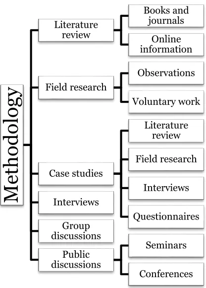
1.8 Methodology ... 25
1.8.1 Literature Review ... 26
1.8.2 Case Studies ... 33
1.8.3 Fieldwork Research and Observations ... 35
1.8.4 Interviews ... 36
1.8.5 Questionnaires ... 37
1.8.6 Group Discussions ... 39
1.9 Research Outline ... 40
Chapter 2 Terms of Reference ... 43
2.1 Introduction... 43
2.2 List of Definitions ... 44
2.2.1 Demountable Buildings ... 44
2.2.2 Evaluation ... 45
2.2.3 Functional Performance ... 47
2.2.4 Small-scale ... 50
vi
2.2.6 Summary ... 53
2.3 Key Factors in the Design and Operation of Public Demountable Buildings ... 54
2.3.1 Function ... 54
2.3.1.1 Spatial Comfort ... 56
2.3.1.2 Usability ... 57
2.3.2 Finance ... 58
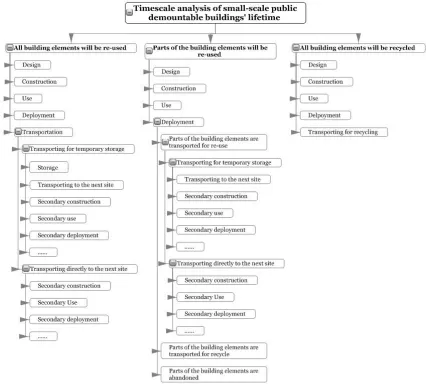
2.3.3 Timescale ... 60
2.3.4 Aesthetics ... 63
2.3.4.2 Visual Appearance ... 63
2.3.4.3 Acceptability to the Users ... 112
2.3.4.4 Appropriateness at Building Sites ... 114
2.4 Analysing the Relationships between Public Demountable Buildings and Sites through Selected Examples ... 115
2.4.1 Projects Deployed in a Single Location ... 117
2.4.1.2 The Model of San Carlo alle Quattro Fontane ... 117
2.4.1.3 Westborough Primary School Cardboard Building ... 118
2.4.1.4 The Prada Transformer ... 120
2.4.1.5 The Norway Pavilion at Shanghai Expo... 121
2.4.2 Projects Deployed in Multiple Locations ... 122
2.4.2.2 The Nomadic Museum ... 122
2.4.2.3 The Paper Church ... 124
2.4.2.4 Chanel Mobile Pavilion ... 125
2.4.2.5 The Harley-Davidson ‘Machine Tent’ ... 126
2.5 Conclusion ... 127
Chapter 3 Review and Synthesis of Analysis and Evaluation Methods ... 130
3.1 Introduction ... 130
3.2 The Role of Evaluation in the Demountable Building Design Process ... 131
3.3 Functional Performance Evaluation Principles ... 134
3.4 The Evaluation Process ... 137
3.5 A Review of the Existing Analysis and Evaluation Methods ... 141
3.5.1 Guidelines Developed by City Councils and Cultural Sectors ... 142
3.5.1.1 Temporary Buildings Design Guide by Aberdeen City Council ... 142
3.5.1.2 Temporary Structures in Historic Places – Guidance for Local Planning Authorities, Site Owners and Event Organisers by English Heritage ... 144
3.5.2 Assessment Methods in Humanitarian Response ... 148
3.5.2.1 UNCHS (Habitat) Guidelines for the Evaluation of Post Disaster Programmes 150 3.5.2.2 EMMA – Emergency Market Mapping and Analysis (Toolkit)... 152
3.5.2.3 Tearfund Shelter and Reconstruction Standards ... 154
3.5.2.4 Post-Occupancy Evaluation of the Container Temporary Housing through Quantitative Surveys and Structured Interviews ... 157
vii
3.5.2.6 ASPIRE (A Sustainability Poverty and Infrastructure Routine for Evaluation) 165
3.5.2.7 Monitoring and Evaluating Post-Disaster Recovery Using High-Resolution
Satellite Imagery ... 169
3.5.3 Methods in Environmental Assessment ... 172
3.5.3.1 ISO 14001:2004 Environmental Management Systems ... 172
3.5.3.2 Using Sensing Systems for Waste Management ... 174
3.5.3.3 IES (Integrated Environmental Solutions) and DesignBuilder ... 176
3.5.3.4 CASBEE (Comprehensive Assessment System for Built Environment Efficiency) 178 3.6 A Conceptual Model for Evaluation ...187
Chapter 4 Case Studies ... 197
4.1 Introduction ... 197
4.2 Chengdu Hualin Elementary School ... 199
4.2.1 Function ... 203
4.2.2 Finance ... 209
4.2.3 Timescale ... 212
4.2.4 Aesthetics ... 214
4.2.5 Contributions ... 219
4.2.6 Limitations ... 221
4.2.7 Recommendations ... 222
4.3 Exxopolis – an Architects of Air Project ... 226
4.3.1 Function ... 229
4.3.2 Finance ... 235
4.3.3 Timescale ... 236
4.3.4 Aesthetics ... 238
4.3.5 Contributions ... 244
4.3.6 Limitations ... 246
4.3.7 Recommendations ... 247
4.4 Kreod ... 251
4.4.1 Function ... 257
4.4.2 Finance ... 258
4.4.3 Timescale ... 259
4.4.4 Aesthetics ... 259
4.4.5 Contributions ... 260
4.4.6 Limitations ... 261
4.4.7 Recommendations ... 262
5.1 Key Findings ... 271
5.2 Limitations and Further Research ... 278
Bibliography ... 288
APPENDICES ... 304
APPENDIX A ... 306
Green & Away Tents Conference Interview Records ... 306
Green & Away Tents Conference Questionnaire...308
Green & Away Tents Conference Questionnaire Results ... 310
Green & Away Tents Conference Report ... 316
APPENDIX B ... 325
The Mina Improved Tent Project Questionnaire ... 325
APPENDIX C ... 327
Questionnaire to the Chengdu Hualin Elementary School Pupils ... 327
Selected Comments from the Pupils at Chengdu Hualin Elementary School ... 328
Questionnaire to the Volunteer Students ... 329
Synthesised Questionnaire Results to the Volunteer Students ... 331
Interview Records (via phone) ... 335
Chengdu Hualin Elementary School Evaluation Questionnaires – Completed by Yasunori Harano and Reiji Watabe on 4 December 2012 ... 338
APPENDIX D ... 339
Questionnaires – UK Premiere of the ‘Exxopolis’ Luminarium ... 339
Questionnaires Results – UK Premiere of the ‘Exxopolis’ Luminarium ... 341
Selected comments from the visitors: ... 341
Exxopolis Evaluation Questionnaires Comments – Completed by Alan Parkinson on 1 December 2012 ... 342
Exxopolis Evaluation Questionnaires – Completed by Alan Parkinson on 27 November 2012 ... 344
APPENDIX E ... 345
Kreod Evaluation Questionnaires Comments – Completed by Chunqing Li on 17 December 2012 ... 345
Kreod Evaluation Questionnaires – Completed by Chunqing Li on 17 December 2012 ... 347
Kreod Evaluation Questionnaires – Completed by Jan Terje Nielsen on 2 April 2013 ... 348
APPENDIX F ... 349
ix
List of Tables
Page No. CHAPTER I
TABLE 1.1. Shelter form comparison 4
TABLE 1.2. Simple shelter comparison proposed by René K. Müller 5
TABLE 1.3. Research methods conclusions 40
CHAPTER II
TABLE 2.1. Selected definitions of ‘evaluation’ from ISO Concept
Database (2010-10-11) 46
TABLE 2.2. Building Performance Mandates, Adapted from
Hartkopf, V. H., Loftness, V. E., and Mill, P. A. D. 48
TABLE 2.3. The scale of static buildings 64
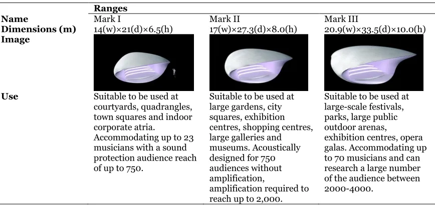
TABLE 2.4. The range of the Soundforms 70
TABLE 2.5. Open Space Types Summarised by James A. LaGro 114
TABLE 2.6. Interrelations in Building Design, G. H. Broadbent,
adapted from T. L. Markus: Building-Environment-Activity-Objectives model
116
TABLE 2.7. A Selection of the Measurements of The Nomadic
Museum in New York, Santa Monica, Tokyo 123
TABLE 2.8. Key Factors of Design and Operation in Demountable
Buildings 129
CHAPTER III
TABLE 3.1. The four assessment sectors of the ASPIRE software 166
TABLE 3.2. A comparison of the ASPIRE case studies 168
TABLE 3.3. Analysis and Evaluation Methods Comparison 186
TABLE 3.4. Explanation of the evaluation indicators 191
TABLE 3.5. Details of the questionnaire 193
Chapter IV
TABLE 4.1. Chengdu Hualin Elementary School case study research
methods 202
TABLE 4.2. Construction materials used 216
TABLE 4.3. Post-Occupancy Evaluation of Chengdu Hualin
Elementary School – A Conceptual Model 225
TABLE 4.4. Post-Occupancy Evaluation of Exxopolis – A Conceptual
Model 250
TABLE 4.5. Post-Occupancy Evaluation of Kreod – A Conceptual
Model 265
xi
List of Illustrations
Page No. CHAPTER I
Figure 1.1. Council house of the Creek Indians 4
Figure 1.2. Fen Wen 4
Figure 1.3. Geodesic dome 5
Figure 1.4. Bow dome 5
Figure 1.5. Zome 5
Figure 1.6. Star dome 5
Figure 1.7. Wigwam 5
Figure 1.8. Section of the Nymph of the Luo River 6
Figure 1.9. Huafang in the West Lake, Hangzhou, China 6
Figure 1.10. WoodX-Column 1948 9
Figure 1.11. “Easy landing” on the Inner Harbor of Baltimore,
Maryland 9
Figure 1.12. Spatial City, project, Perspective, 1958–59 12
Figure 1.13. Spatial City, Elevated Blocks, project, Paris, France,
Perspective, 1959 12
Figure 1.14. The Burnham Pavilion 15
Figure 1.15. London 2012 Olympic Cauldron 15
Figure 1.16. The Haitian street theatre Zhovie in performance 18
Figure 1.17. A preliminary version of the structure built at ETH
Zürich 20
Figure 1.18. The structure and the crew 20
Figure 1.19. Research hypothesis, aim and objectives 24
Figure 1.20. Research methodology diagram 26
Figure 1.21. The Treetents 29
Figure 1.22. The prototype of DesertSeal, exhibited at MoMA
(Museum of Modern Art), New York since 2005 29
CHAPTER II
Figure 2.1. Linkage scheme 55
Figure 2.2. Topologic Transformation of a linkage scheme 55
Figure 2.3. The dual of the linkage scheme 55
Figure 2.4. Timescale analysis of small-scale public demountable
building‘s lifetime 62
Figure 2.5. The aspects of visual appearance in demountable
buildings (Summarised by the author) 63
Figure 2.6. The Basketball Arena for London 2012 Olympic Games 66
Figure 2.7. The UK Pavilion for Shanghai Expo 2010 66
Figure 2.8. The Temporary Pavilion for the 75th Lisbon 2005 Book
Fair 67
Figure 2.9. The entrance to the pavilion 67
Figure 2.10. A single micro dwelling 68
Figure 2.11. Three dwellings attached together, Space Soon,
Roundhouse, Arts Catalysts, London, UK, 2006 68
Figure 2.12. The Soundforms during a performance 70
Figure 2.13. The Soundforms design 70
Figure 2.14. A tent unit 71
Figure 2.15. Mina Tents Valley 71
xii
Figure 2.17. The Swell House 73
Figure 2.18. The Cluny Summer Pavilion 74
Figure 2.19. A close view of the pavilion 74
Figure 2.20. Mobile Garden Tent for the Theodor-Heuss-Stiftung,
Stuttgart 75
Figure 2.21. Starwave Tent for La Biennale di Venezia 1996‘, Italy 75
Figure 2.22. Air Forest installed in City Park, Denver, Colorado, USA 77
Figure 2.23. A close view of Air Forest 77
Figure 2.24. CCTV footage released by the police of the Dreamspace
inflatable sculpture was lifted up into the air 78
Figure 2.25. Dreamspace installed in front of The Metropolitan
Cathedral, Liverpool 78
Figure 2.26. Inside the Dreamspace 78
Figure 2.27. A single 8x8 m tent 78
Figure 2.28. The Tent City in the Mina Valley 78
Figure 2.29. The embedded project - For Earts 2008 Shanghai 80
Figure 2.30. Inside the factory 80
Figure 2.31. The Norway Pavilion 82
Figure 2.32. The interior design of the Pavilion 82
Figure 2.33. The Jellyfish Theatre Outside 83
Figure 2.34. The Jellyfish Theatre Inside 83
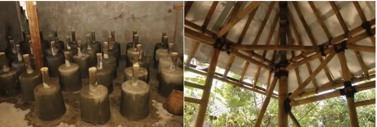
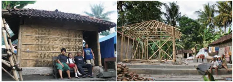
Figure 2.35. Foundation pads cast with bamboo connection 84
Figure 2.36. Bamboo constructed roof 84
Figure 2.37. A completed transitional shelter built through cash
grants 85
Figure 2.38. A transitional bamboo shelter built on the site of a
destroyed house 85
Figure 2.39. German-Chinese House, Shanghai, China 86
Figure 2.40. An inside view of the pavilion 86
Figure 2.41. Two volunteers soaking a paper tube in the fire proof
paint 88
Figure 2.42. Pater tubes after treated with fire proof paint 88
Figure 2.43. Timber inside a paper tube to support the tube structure 88
Figure 2.44. Paper Arbor-Nagoya, Japan, 1989 88
Figure 2.45. Paper Arbor in the Evening 88
Figure 2.46. Miyake Design Studio Gallery-Shibuya, Tokyo, Japan,
1994 89
Figure 2.47. The Interior Design of the Miyake Design Studio
Gallery-Shibuya 89
Figure 2.48. The Cardboard House in Sydney, 2005 90
Figure 2.49. Inside the Cardboard House 90
Figure 2.50. The Cardboard House at the exhibition 90
Figure 2.51. The Cardboard Café bar area 91
Figure 2.52. The seating area and two towering arches 91
Figure 2.53. The Spanish Pavilion at Shanghai Expo 2010 92
Figure 2.54. Different colour wicker panels inside the pavilion 93
Figure 2.55. Bug Dome during the 2009 Shenzhen & Hong Kong
Bi-city Biennale of Urbanism/Architecture 94
Figure 2.56. Bug Dome “covered” in plants 94
Figure 2.57. Sandworm 95
Figure 2.58. Inside the Sandworm 95
xiii by D. J. Huppatz
Figure 2.60. An overview of Maison Tropicale 96
Figure 2.61. The Future Shack 97
Figure 2.62. The interior design of The Future Shack 97
Figure 2.63. The Open Restaurant Box 97
Figure 2.64. The Closed Restaurant Box 97
Figure 2.65. The Model of Spanish Pavilion - Steel Structure 98
Figure 2.66. The Model of Spanish Pavilion - Steel Structure Attached
to Wicker Surface 98
Figure 2.67. Mirazozo, Sydney, Austria, 2011 100
Figure 2.68. Inside a Luminarium 100
Figure 2.69. “Kiss the Frog” before being inflated 101
Figure 2.70. “Kiss the Frog” fully inflated 101
Figure 2.71. The “Container Village” with an industrial glass shell 102
Figure 2.72. The architectural drawing of the design 102
Figure 2.73. Demountable concrete frame design 103
Figure 2.74. Re-usable wax 104
Figure 2.75. Wax negative/concrete positive 104
Figure 2.76. 1×1 m double curved free-form wax element, produced by
a robotic process, and the concrete positive cast against it 104
Figure 2.77. The Portable Gallery 105
Figure 2.78. Inside the Portable Gallery 105
Figure 2.79. The reflective roof inside the Gallery 105
Figure 2.80. Gabion test assembly, London Regatta Centre 106
Figure 2.81. Gabion load testing, Turin 106
Figure 2.82. Waldpavilion Gulpwald, Willisau 106
Figure 2.83. Gabion walls constructed from steel and woods 106
Figure 2.84. Gabion wall 107
Figure 2.85. Snow gun making snow 108
Figure 2.86. Snow on the steel forms 108
Figure 2.87. Transporting ice-blocks 108
Figure 2.88. Art Suite 302 108
Figure 2.89. An overview of the temporary ―ice building 109
Figure 2.90. Festival visitors enjoy an ice slide 109
Figure 2.91. An ice labyrinth 109
Figure 2.92. Wooden Model of Borromini‘s Church of San Carlo alle
Quattro Fontane in Rome on The Lakeshore Lugano, Switzerland
117
Figure 2.93. Inside the Wooden Model 117
Figure 2.94. Westborough Primary School Cardboard Building222 118
Figure 2.95. Rotating Prada Transformer 120
Figure 2.96. Prada Transformer outside The Gyepnghui Palace 120
Figure 2.97. A relocated “tree” after Expo 121
Figure 2.98. The Nomadic Museum in New York 122
Figure 2.99. The Nomadic Museum in Santa Monica 122
Figure 2.100. The Nomadic Museum in Tokyo 122
Figure 2.101. The Paper Church in Kobe 124
Figure 2.102. Inside the Paper Church in Kobe 124
Figure 2.103. The Paper Church in Taiwan 124
Figure 2.104. Chanel Mobile Pavilion in Hong Kong 125
Figure 2.105. Chanel Mobile Pavilion in Tokyo 125
xiv
Figure 2.107. Chanel Mobile Pavilion in Paris 125
Figure 2.108. Inside the ‘Machine Tent’ 126
CHAPTER III
Figure 3.1. The iterative structure of the design 133
Figure 3.2. The Shearing Layers of Change 136
Figure 3.3. A Christmas dome at Liverpool ONE 144
Figure 3.4. A temporary commercial structure 144
Figure 3.5. A large tent in front of John Lewis – the department
store 144
Figure 3.6. Container temporary housing – Onagawa, Miyagi 157
Figure 3.7. An exterior view 157
Figure 3.8. Paper tubes in transportation 157
Figure 3.9. Paper Partition System in a stadium 157
Figure 3.10. An interior view of the temporary housing 158
Figure 3.11. A market in the centre of the site 158
Figure 3.12. Shigeru Ban and VAN team in a meeting before carrying
out survey 159
Figure 3.13. A VAN team member interviewing a resident with a
survey 159
Figure 3.14. Data entry dialogue screen 167
Figure 3.15. Sub-theme scoring screen 167
Figure 3.16. Transitional Shelter: Ban Nam Khem, Thailand (24 June
2002) 171
Figure 3.17. 2 January 2005 171
Figure 3.18. 28 February 2006 171
Figure 3.19. First generation of trash tags 175
Figure 3.20. Composite map of the recorded traces 175
Figure 3.21. Building Environmental Efficiency (BEE Ranking/Chart),
Life Cycle CO2 (Global Warming Impact Chart), Primary Assessment Results (Radar Chart)
178
Figure 3.22. CASBEE for Temporary Construction Criteria 180
Figure 3.23. The FFTA weighting diagram – a possibility 194
CHAPTER IV
Figure 4.1. Chengdu Hualin Elementary School 197
Figure 4.2. A choir performance inside Exxopolis 197
Figure 4.3. Kreod in the evening 197
Figure 4.4. A full size model of a residence dwelling in the campus of Southwest Jiaotong University (during construction) 199
Figure 4.5. Completed model 199
Figure 4.6. Chengdu Hualin Elementary School site plan 200
Figure 4.7. Inside view of a classroom 203
Figure 4.8. Inside view of an office 203
Figure 4.9. Electronic wall fan 203
Figure 4.10. Thermal comfort (summer) 203
Figure 4.11. Thermal comfort (winter) 204
Figure 4.12. Thermal comfort - humidity 204
Figure 4.13. The School is built next to a main road 205
Figure 4.14. A playground is located between the paper building and
the concrete building 205
Figure 4.15. Acoustic quality – noise from road 205
Figure 4.16. Acoustic quality – noise from other classrooms 206
xv
Figure 4.18. Students in a classroom during a class break 207
Figure 4.19. A small corridor space between the two terraced
classrooms 207
Figure 4.20. Spatial environment 208
Figure 4.21. The fluorescent lights on the ceiling in one classroom 208
Figure 4.22. Lighting environment 209
Figure 4.23. A classroom in the concrete building was used as a
workshop to store materials and construct small joints 210
Figure 4.24. A photo of some of the volunteers 211
Figure 4.25. A classroom was used as temporary accommodation for
the volunteers 211
Figure 4.26. A chair made from recycled timber panels, designed by
Hironori Matsubara 212
Figure 4.27. A bin made from left over paper tubes, painted by the
school students 212
Figure 4.28. Ban’s sketch – details of the section 213
Figure 4.29. Details of the timber joints 213
Figure 4.30. Timber joints were transported by a truck 213
Figure 4.31. A view of the surrounding environment 215
Figure 4.32. Volunteers working on the building roof 215
Figure 4.33. Paper tubes being stored inside a classroom in the
concrete building 216
Figure 4.34. Paper tubes being treated by waterproof paint 216
Figure 4.35. The end of a paper tube was damaged by the rain 217
Figure 4.36. The metal replacement 217
Figure 4.37. A crack appeared on the floor in one of the classrooms 217
Figure 4.38. Opinions on deign 218
Figure 4.39. Opinions on building experience 218
Figure 4.40. Parents’ opinions on design 219
Figure 4.41. The crack shows that the PVC door and the paper tubes
are detached 220
Figure 4.42. The frame structure of the building 220
Figure 4.43. Newark environment (1988) 226
Figure 4.44. Eggopolis (1990) 226
Figure 4.45. Exxopolis (2012) 228
Figure 4.46. A choir performance inside Exxopolis 228
Figure 4.47. The principal dome of Exxopolis 229
Figure 4.48. The intricate windows of the Exxopolis Cupola 229
Figure 4.49. The main entrance 230
Figure 4.50. The second entrance 230
Figure 4.51. Gender 231
Figure 4.52. Age group 231
Figure 4.53. Architectural/arts training experience 231
Figure 4.54. Travelling 232
Figure 4.55. Where did you hear about the Exxopolis Luminarium 232
Figure 4.56. Previous experience 232
Figure 4.57. Attending events 233
Figure 4.58. Did you feel crowded inside the structure 233
Figure 4.59. A wheelchair user inside Exxopolis 233
Figure 4.60. Visitors enjoy their experience inside the structure 233
Figure 4.61. Did you find the structure exit easily 234
xvi and equipment
Figure 4.63. Parts of the structure being prepared in the studio 237
Figure 4.64. Electronic fans 237
Figure 4.65. The team prepares the structure before inflation 237
Figure 4.66. Metal pegs are used to tie the structure to the ground 237
Figure 4.67. How long did you stay inside the structure 238
Figure 4.68. The coloured PVC plastics are stored in the studio in
Nottingham 239
Figure 4.69. Red dome 239
Figure 4.70. Blue dome 239
Figure 4.71. Green dome 239
Figure 4.72. Purple dome 239
Figure 4.73. Visitors’ opinions on colours 240
Figure 4.74. Visitors’ opinions on light 240
Figure 4.75. Did you feel relaxed and calm inside the structure 242
Figure 4.76. Visitors’ opinions on their experience 242
Figure 4.77. Would you like to come back 242
Figure 4.78. Lakeside Arts Centre venue 243
Figure 4.79. Did you find the festival site easily 244
Figure 4.80. Windows Projects workshop 245
Figure 4.81. Workshop teams handcraft the “windows” 245
Figure 4.82. A training session for disabled children inside an
Architects of Air structure 246
Figure 4.83. A 3D modelling image of Exxopolis 247
Figure 4.84. A baseball is used on the metal peg to protect the
structure 248
Figure 4.85. The architectural model of d_pod (Kreod) 252
Figure 4.86. A conceptual image of inside the structure 252
Figure 4.87. The design details of Kreod 253
Figure 4.88. The steel foundation being fabricated in Nottingham 254
Figure 4.89. The CNC Robotics arm 255
Figure 4.90. Wooden components ready to be used in construction 255
Figure 4.91. The first component being constructed 255
Figure 4.92. The wooden components 255
Figure 4.93. The second component being constructed 256
Figure 4.94. The third component being constructed 256
Figure 4.95. Kreod at the opening ceremony 257
Figure 4.96. Three components can be arranged differently 257
Figure 4.97. An inside view 257
Figure 4.98. Design instruction 258
Figure 4.99. The shadows on the membrane sheet 260
Figure 4.100. The faulty wooden components were burnt for hot water 262
Figure 4.101. A few faulty components were designed as wall shelves 262
CHAPTER V
Figure 5.1. Research structure diagram 271
Figure 5.2. A sketch of changing the project space 280
Figure 5.3. An open air concert at the Zócalo 282
Figure 5.4. The Nomadic Museum at the Zócalo 282
Acknowledgements
I would first like to thank the School of Architecture, University of Liverpool, for their continued support over the past three years. I would also like to express my sincere thanks to the University of Liverpool Graduate Association (Hong Kong). The Association has financially enabled me to test parts of this research in conference presentations, and to finalise the results in a number of publications. In particular, I would like to thank my supervisors, Professor Robert Kronenburg, for his invaluable guidance and substantial support, and Mr John Lewis, for his insightful advice and positivity. I am extremely grateful for their close supervision. I would also like to thank Dr Carolina Stevenson for her valuable advice on the typology of kinetic structures, Dr Halim Boussabaine for his good advice on design quality indicators, and Mr Moshabab Aljarman for his information on the Mina Tents Valley in Mecca.
My sincere gratitude goes to Professor André Brown and Professor Barry Gibbs, for their positive support and friendly advice. Thanks also go to Marion, Craig and Chris at the School of Architecture, University of Liverpool, for their kind help. My thanks also go to my former supervisor, David Bromilow at the University of Leeds, who guided and encouraged me on this academic path when I studied at the Design School from 2008 to 2009.
I would like to say thank you to Yasunori Harano, Reiji Watabe, Lin Hou, Hong Yin, Jing Deng, Xiaodu Liu, Alan Parkinson, Mado Ehrenborg and Chunqing Li for their kindness and generosity in providing solid information and long-term cooperation for the case studies.
A special thank you goes to Jane Clayton, Nick Webb and Mike Otchie, who have accompanied me on this wonderful journey. I would also like to thank Ataa, Antoinette, Shama, Judith, Haniyeh, Anna, Mai, Yemi, Yusuf, Elaheh, Duygu, Sureepan and Ruxandra for their friendship and support.
xix
Preface
My interest in moveable architecture started when I studied at the Design School, University of Leeds. My graduation project was to design a small space for temporary museum exhibitions. During the design process, I was particularly concerned with access for people with disabilities who are often unable to experience museum exhibitions in the same way as other visitors. One of the limitations of traditional museum exhibitions is that the objects cannot easily be relocated, and my field of research focused on the more interesting and challenging moveable objects. I was fortunate to meet Ceinwen Paynton the Principal Keeper at Leeds City Museum, who introduced me to Caroline McDonald, Curator of Archaeology at Colchester Museum, and Gabrielle Hamilton, Curator of Community History and Antonia Lovelace, Curator of Anthropology, from Leeds Museum Discovery Centre. I discovered the idea of a ‘museum in a suitcase’, where curators fill a vintage suitcase with museum objects and take them on journeys to outdoor events. I began to re-think my current design and completed a portable museum design project. The final design was a house-shaped structure that displays museum objects in many protected boxes hung from trees in different parks during both daytime and early evening.
1
1
Introduction
Travel and change of place impart new vigor to the mind.
– Lucius Annaeus Seneca1
1.1
Introduction
The term demountable building encompasses a wide range of constructions that have a shared attribute: the ability to be deployed and transported from site to site for re-use or recycling. Many other terms, such as moveable, mobile, portable, foldable,
deployable, transformable, relocatable, adaptable, kinetic and adaptive, are often used to describe similar designs. Although these terms share a similar meaning, they can be interpreted differently depending on the specific circumstances. This thesis will focus on demountable buildings because:
(i) They have been widely used around the world and are becoming increasingly important. There is a growing need for empirical research related to this area for many reasons, including the application in areas of high population and urbanisation.
(ii) They are distinct from static buildings in the process of dismantling, a process which is, therefore, central to the analysis of this particular type of building. Unlike demolition, dismantling enables valuable construction materials to be salvaged. The hypothesis here is that the evaluation of demountable buildings
2
can be considered by observing and analysing the dismantling process. This process can be divided into two main aspects: environmental performance; and functional performance. However, in this case, the focus remains on functional performance.
(iii) The majority of contemporary demountable buildings have been located in open public spaces with easy access. A well-presented demountable building does not only save construction time and costs, but can also help to provide economic benefits, such as raising public awareness and advertising exhibited projects.
Small-scale projects are flexible in function and adaptable in structure. They are the most commonly used type of contemporary moveable architecture. They require low budgets, small working teams and small building sites and, most importantly, the ability to be assembled and dismantled in a relatively short period of time. Small-scale projects can encourage design innovation and can be useful for design experiments. Analysing such small-scale projects can help to improve the understanding of the design of all buildings.
Focus is on public buildings for two main reasons: universality because the majority of contemporary demountable buildings are for public use, despite evidence of a range of demountable residential shelters and temporary houses; and diversity, because public-use demountable buildings fulfil many temporary needs, such as non-emergency transitional schools, ephemeral exhibitions and seasonal entertainment.
The purpose of examining functional performance is to assess if, and how, the requirements of the design have been achieved. The value of this research is, therefore, in the establishment of a set of relevant criteria as a systematic evaluation option, enabling project operators to begin to address functional performance from a public perspective and reflect on the scope of their projects. This relies upon the assumption that a specific evaluation method for public demountable buildings can be adapted to other types and scales of demountable buildings in future research. The possible approaches for how the research results can fit within the broader area are recommended in the concluding chapter.
3
problems and perspectives, presenting the research hypothesis, aim, objectives and study subject before outlining the structure of the thesis is described.
1.2
Prehistoric Background and Traditional Shelters
The use of demountable buildings began in ancient times, evidence for which can been seen around the world, including in the partly subterranean houses of cane and grass, with whale rib bones for internal support, located in the Chilca valley of central Peru (Figure 1.1.). The site was known to be occupied around 5,400 years ago, and early farmers living there grew beans and gourds, and collected many wild plants, shellfish and fish. Other ancient forms of early shelter include tipis, tents, yurts and igloos. For example, the classic dwelling of Siberian and Mongolian nomadic herders provides the minimum of exposed surfaces and maximum stability to adapt to the migratory lifestyle as people move seasonally for food and for their animals to forage.2 Evidence can also been seen in the snow houses, or igloos, developed for the tundra of the Arctic and used by the Inuit as winter homes or temporary bases for hunting parties.3
Jonathan Horning states that the primary and oldest function of shelters is to provide of protection against weather, extreme temperatures and foes. Secondary functions are the provision of comfort, aesthetics and privacy.4 Shelters were also broadly used for military purposes, and as recorded in The Art of War – the ancient Chinese military treatise attributed to Sun Tzu, who lived between 544 BC and 496 BC – a type of machine called Fen Wen (Figure 1.2.), made from wood and covered with animal skin, was used to carry ten people from one location to another. It was used by soldiers who were protected from stones and other weapons by the house-shaped structure.
2 Marilyn Walker, "Circumpolar Shelter," In Andreas Muller, Arctic Perspective Cahier No. 1 (Hatje Cantz
Verlag GmbH & Co KG, 2011), 75.
3 Jonathan Horning and Brock Horning, Simple Shelters : Tents, Tipis, Yurts, Domes and other Ancient
Homes (New York: Walker & Co., 2009), 46.
4
FIGURE 1. 1. - FIGURE 1. 2. Ancient shelter in Peru;5 Fen Wen6
Horning states that all ancient shelters, whether nomadic, seasonal or settled,7 evolved as functional responses to the local climate, the availability of materials and temporal requirements. He believes that the form of ancient shelters is related to the relevant geological and climate conditions, his general classification is presented in the following table:
TABLE 1.1. Shelter form comparison8
Shelter Form Geographical
Location Weather Material
Tipi North America Plains, dry prairie Fabrics, animal skin,
wood
Conical hut Generic Africa Tropical and temperate
zones Mud, clay, sod, stones, straw
Igloo Northern Ice belt, tundra Snow blocks, animal
skin
Black tent Dry desert, Iran, Tibet,
North Africa, Arabia, Iraq, Syria
Hot, dry Wood, fabrics, animal
skin
Yurt Asia (Turkey, Mongolia,
Kazakhstan, Kyrgyzstan)
Semi-arid steppes Wood, timber, fabrics, animal skin
Bamboo hut Tropical, rainforest Hot, humid Bamboo, straw
Yaranga Asia, Sub-Arctic Cold, humid Wooden frame, reindeer
skin, canvas
Despite their simple appearance, the shelters are not simplistic and they attract researchers wishing to study their natural form from various perspectives. A comprehensive categorisation of simple shelters is proposed by René K. Müller, who makes and inhabits traditional temporary shelters. Based on practical experience and theoretical knowledge, Müller distinguishes simple shelters as tipis, yurts and domes.
5 This model is in the American Museum of Natural History in New York, United States. 6 "Gong Cheng Shu," ed. Fen Wen.
5
He further identifies the dome typology as having five types: geodesic dome, bow dome, zome, star dome and wigwam.9 Interestingly, Müller assesses each structure type and ranks them based on four criteria: simplicity, portability, comfort and size flexibility (Table 1.2.).10
FIGURE 1. 3. - FIGURE 1. 7. Geodesic dome; Bow dome; Zome; Star dome; Wigwam11
TABLE 1.2. Simple shelter comparison proposed by René K. Müller12
Simple Shelter Comparison
Simplicity Portability Comfort Size flexibility Overall
1 2 3 4 5 1 2 3 4 5 1 2 3 4 5 1 2 3 4 5
Tipi 3
Yurt 3.5
Dome Geodesic
dome 2.75 Bow
dome 3 Zome 3
Star
dome 2.75 Wigwam 3
Based on Müller’s assessment, the yurt is ranked as having the highest score among the different types of shelter, which indicates best performance in construction and function. The result also suggests that the wooden-framed yurt is the most portable structure, although it has an average flexible size and requires complex construction skills. Robert Kronenburg categorises simple shelters into: tents, as utilising tensile fabric engineering with minimal and relatively heavy-compression elements; tipis as single cells made of a space frame, and incorporating a twin-skin environmental wall for
9 René K. Müller, "Simply Differently," http://simplydifferently.org/ (accessed 12 January 2013). 10 Ibid.
6
ventilation and insulation; and yurts as manufactured using modular systems incorporating a geodetic wall structure.13
In addition to dwellings that were built on land, there is a long history of floating housing, such as the Huafang, a well-known boat-house type in China. This translates from Mandarin as “well decorated boat”, with the earliest recorded picture of a Huafang being in a painting, Nymph of the Luo River (Figure 1.8.), by celebrated ancient Chinese painter Gu Kaizhi, who lived from AD 344 to AD 406 (Jin Dynasty).14 The Huafang was developed further in both function and appearance during the Tang Dynasty (AD 618– 907), Ming Dynasty (AD 1368–1644) and Qing Dynasty (AD 1644–1912). In ancient China, China wood oil (tung oil) was used as a drying oil to protect wooden boats from water. Tung oil is obtained by pressing the seed from the nut of the tung tree. Clearly inspired by ancient Chinese timber architecture, the design of the Huafang provided a comfortable and luxurious place for outdoor entertainment, including singing, dancing and plays. The performance stage could be relocated as a whole onto a boat to provide people with an opportunity to enjoy plays inside a “house” with a natural moving background (Figure 1.9.).
FIGURE 1. 8. - FIGURE 1. 9. Section of the Nymph of the Luo River;15 Huafang in the West Lake,
Hangzhou, China
A key characteristic of ancient shelters is the fact that they were man-made with simple tools and, therefore, the aesthetics relied heavily on the craftsman’s skills. They were constructed from natural materials and, because of limited resources, some were treated with simple natural materials. Although these traditional building types require
13 Robert Kronenburg, Houses in Motion (London: Academy Editions, 2002), 18-23.
14 The story of this painting is based on a long poem written by Prince Caozhi (AD 192–232), which tells the
romantic tale of Caozhi’s meeting with the Nymph of the Luo River (Luoshen), a daughter of the mythical ruler Fuxi.
7
relatively low technology skills, their design systems have, for generations, inspired architects and engineers towards more sophisticated designs and construction techniques. Even today, architectural historians and researchers are still fascinated by the form, function and history of these ancient and traditional building types, and there is no doubt that their value continues to support and motivate contemporary architects and designers in developing more advanced building designs.
1.3
Prefabrication, Invention and Lightweight
Constructions
The 19th century period of industrialisation offered prefabrication and transportation, and had a revolutionary impact on demountable buildings. Arnt Cobbers, Oliver Jahn and Peter Gössel write: “The use of mass-produced nails, rather than expensive hand-wrought nails, made it possible to construct a house solely out of boards that any sawmill could deliver by using nailed joints. Mortise and tenon joints, as used in timber frame houses, were no longer necessary.”16 The emergence and spread of prefabrication is closely related to the life of pioneers in early days, and the first manufacturer to address the more general issue of the mass-market demountable building was John Manning, a London carpenter and builder who, in around 1833, conceived the Manning Portable Colonial Cottage.17 This structure was designed to utilise a small volume for effective use of shipping space, to be easy to erect and, as repetitive parts were of the same dimensions, to be modular.18 Cobbers, Jahn and Gössel argue that long before the word prefabrication existed, Manning had developed a system that worked by precisely adhering to standard measurements, with panels, posts, and plates that each had the same length, breadth and thickness and, therefore, could be easily installed. As such, Manning created the prototype of the modern prefabricated house.19
Prefabrication is “a child of nineteenth-century industrialisation”20 and the Crystal Palace, which was exhibited in London in 1851, is an outstanding example of the new industrial mindset in building culture, as well as of the innovative organisation of
16 Arnt Cobbers, Oliver Jahn, and Peter Gössel, Prefab Houses (Köln: Taschen, 2010), 9. 17 Ibid., 30.
18 Kronenburg, Houses in Motion: 44.
8
planning, building sites and building processes.21 Ulrich Pfammatter assesses the contribution of the Crystal Palace by stating that:
It demonstrated how constructing enormous volumes with the tightest of budgets and time restrictions and the greatest of precise detail could be achieved rationally and with an industrial mindset, and reveals an understanding of a building as a multi-layered overall system and the building process as a multi-disciplinary problem, which was new at the time and anticipated the future of modern construction.22
In the 20th century, many architects, designers, engineers and inventors showed a particular interest in designing and manufacturing demountable and moveable housing. For example, the Dymaxion Deployment Unit (DDU) – developed by Richard Buckminster Fuller in collaboration with the Butler Manufacturing company in Kansas City in 1940 – was a project commissioned by the United States government. The DDU, in which the external wall and the supporting structure formed a single unit, could be easily erected and dismantled. There are many other historical examples, such as Maison Tropicale, designed by Ateliers Jeans Prouvé from 1949 to 1951 in Maxéville, France; Futuro, a UFO-like house designed by Finnish architect Matti Suuronen in 1965; and Bulle Six Coques, designed by French architect and city planner Jean Maneval in around 1967.
Alongside the development of industrial inventions, research and practice in lightweight construction also flourished during the same time period. According to Winfried Nerdinger and Rainer Barthel, Frei Otto’s work in lightweight and adaptable constructions first caused a stir in 1954 with his doctoral thesis Suspended Roofs,23 and he has continued to produce important stimuli and innovative ideas since.24 Otto was determined to reject any form of heavy, solid, earthbound building, and his German Pavilion at Expo 67 in Montreal brought “international recognition for the transformation into a new, peaceful democracy”.25 His demountable umbrella design was widely used and appreciated around the world, including Europe and the Middle East. Together with Bodo Rasch, Otto’s inventions were remarkably successful in Saudi
21 Ulrich Pfammatter, Building the Future : Building Technology and Cultural History from the Industrial
Revolution until Today (Munich; New York: Prestel, 2008), 74.
22 Ibid.
23 A suspended roof means a membrane stretched between fixed points that forms a roof structure and roof
covering at the same time. Frei Otto’s thesis Suspended Roof was given a grade of “good”; it was published by the Bauwelt Publishing House in Berlin in 1954 and soon had a large influence on architectural practice.
24 Frei Otto, Winfried Nerdinger, and Architekturmuseum Technische Universität München, Frei Otto :
Complete Works : Lightweight Construction, Natural Design (Basel; Boston: Birkhäuser, 2005), 6.
9
Arabia and the Gulf region, for example, the adaptable umbrella in the inner courtyard of the Mosque of the Prophet, Medina, which was designed and constructed in 1992, and provides shade for pilgrims through the use of common materials and aesthetically pleasing surfaces.
Together with lighter forms of construction in steel, glass, fabrics and plastics, the “tensegrity” experiments in 1948 established a new era with regards to space, load-bearing structures and the technology emerging in architects’ and engineers’ fields of design. The “tensegrity” structural principle was discovered by Kenneth Snelson and Buckminster Fuller, and in, “The Art of Tensegrity”, Snelson states that:
In 1996, Vliyme 11 Nos. 1 & 2 of this Journal, the different views of Buckminster Fuller, David George Emmerich and Kenneth Snelson were thoroughly debated. I told of Mr Fuller’s 1959 New York Museum of Modern Art exhibition when he finally credited me for discovering the tensegrity principle.26
FIGURE 1. 10. - FIGURE 1. 11. WoodX-Column 1948;27 “Easy landing” on the Inner Harbor of Baltimore,
Maryland28
“Tensegrity”, by combining the words tensile and integrity means integral tensile stress.29 Donald E. Ingber defines it as an architectural system in which structures stabilise themselves by balancing the counteracting forces of compression and tension, and compares cell composition to both Snelson’s sculptures and Buckminster Fuller’s geodesic domes.30 Chris Wilkinson, of Wilkinson Eyre Architects Company, lists the
26 Kenneth Snelson, "The Art of Tensegrity," International Journal of Space Structures International
Journal of Space Structures 27, no. 2 (2012): 71.
27 ———, "WoodX-Column1948," (1948).
28 ———, "“Easy landing” on Baltimore Maryland’s Inner Harbor," (2010).
29 Pfammatter, Building the Future : Building Technology and Cultural History from the Industrial
Revolution until Today: 84.
30 Donald E. Ingber, "The Architecture of Life," http://time.arts.ucla.edu/Talks/Barcelona/Arch_Life.htm
10
benefits of “tensegrity” by stating that: “As architects, we are attracted to tensegrity structures for their visual lightness and their efficiency. They offer the maximum strength for a given amount of material, which keeps the member sizes slender and light.”31 The “tensegrity” method of construction pointed to a new direction in architecture construction and it continues to be used as an experimental method of construction, providing grounds for further research and practice.
1.4
The City of the Future – Mobile City Planning and the
Plug-in City
The 1960s was a period of exciting, radical and subversive cultural and political events which sparked a social revolution throughout much of the Western world. Contemporary scholars pursued their visionary ideals of a better future, led by the application of technology towards social causes. Carolina Stevenson states that the architecture of this period aimed to harmoniously and creatively integrate human happiness, mobility and environment. Under this theoretical atmosphere, the “utopia of the modern nomad” reached its pinnacle with the radical European avant-garde movement of the 1960s and 1970s.32
One of the most representative examples is the inspiring work of Hungarian architect Yona Friedman,33 who now lives in France. Lebesque and Helene Fentener van Vlissingen state that the work of Friedman, particularly in its first phase, termed “L’Architecture Mobile,”34 aimed to provide “maximum flexibility”35 and has led architects, urban planners, theorists and researchers to a utopian world by
31 Chris Wilkinson, "Responsive Structures,"(2001),
http://www.wilkinsoneyre.com/texts/essays/responsive-structures.aspx (accessed 17 December 2012).
32 Carolina Stevenson, "The Evolution of Temporary and Permanent Kinetic Architectural Structures"
(paper presented at the International Association for Shell and Spatial Structures (IASS) Symposium 2010, Shanghai, China, Shanghai, 2010), 832.
33 Yona Friedman was born in Budapest, Hungary, in 1923 and studied architecture at the Technical
University, Budapest. One of his most important contributions is his theory of mobile architecture and the mobile city. According to Professor Alfredo Brillembourg – one of the directors at Urban Think Tank, who also holds the chair for Architecture and Urban Design at the Swiss Institute of Technology, ETH in Zürich – the only way to contact Friedman for interviews is by using fax machines, because he does not use the Internet.
34 “L’Architecture Mobile” translates as Mobile Architecture.
35 Sabine Lebesque and Helene Fentener van Vlissingen, Yona Friedman : Structures Serving the
11
incorporating “principles based on the absolute requirement of individual freedom”.36 Friedman co-founded GEAM (The Groupe d’Études d’Architecture Mobile),37 a group of young European architects and engineers who were all interested in structures and technical details.38 The core ideas he proposed in the 1960s were that: “New constructions serving for individual shelters must: 1. Touch a minimum surface of the ground; 2. Be demountable and moveable; 3. Be transformable at will by the individual inhabitant.”39
In addition to mobile architecture, Friedman also showed interest in urban design. In the Spatial City project (Figures 1.12. and 1.13.), Friedman was inspired by the housing shortage in France during the late 1950s, and “raised a second city fifteen to twenty meters above the existing one”.40 This project was “designed for construction anywhere, and meant to be adapted to any climate”.41 In a conversation with Larry Busbea, Friedman explained that GEAM was dissolved in 1962 because “other members were not developing their own ideas actively enough”.42 Busbea later argued that Friedman “elaborated his notion of mobility in architecture with an overabundance of obscure terminology and neologisms”.43 Friedman’s interests in planning did not stop, and he seemed particularly keen on the theory that he called “the reasoning”.44 In his book
Toward a Scientific Architecture, he states that the works from Schulze-Fielitz (1961), Kenzo Tange (1962), Kurokawa, the Archigram group, Safdie, Bofill and Mühlestein “were too much inspired by the kind of visualizations (drawings or photographs of models) that have appeared in professional journals since 1959”,45 and that “for the most part, these architects also did not understand that the forms which I proposed
36 Ibid.
37 Their first group meeting took place in Rotterdam in 1958. The original members included Yona
Friedman, David Georges Emmerich, Jean-Pierre Pecquet, Jerzy Soltan [Soltan was no longer associated with the group after the initial meeting] and Jean Trapmann, although other members, such as Werner Ruhnau, Günther Günsche, Frei Otto, Paul Maymont and Eckhard Schulze-Fielitz joined a few months later.
38 Larry Busbea, Topologies : The Urban Utopia in France, 1960-1970 (Cambridge, Mass.: MIT Press,
2007), 62.
39 Yona Friedman, Program of Mobile Urbanism, in Ockman, Joan, and Edward Eigen. 1993. Architecture
Culture, 1943-1968: A Documentary Anthology. [New York]: Columbia University Graduate School of Architecture, Planning, and Preservation, quoted in ibid.
40 Howard Gilman, Terence Riley, and Art Metropolitan Museum of, The Changing of the Avant-garde :
Visionary Architectural Drawings from the Howard Gilman Collection (New York: Museum of Modern Art, 2002), 40.
41 Ibid.
42 Busbea, Topologies : The Urban Utopia in France, 1960-1970: 64.
12
were only the result of this very strict reasoning”.46 Busbea summarises part of Friedman’s contribution as:
Friedman’s development of mobile architecture tapped into the national craze for bricolage, or the home repair and improvement projects that became popular during the fifties and sixties across Europe.47 Friedman’s insistence that architects step aside and allow the users of urban infrastructures to have absolute and final say in the configuration of their dwellings was the futuristic extension of bricolage.48
FIGURE 1. 12. - FIGURE 1.13. Spatial City, project, Perspective, 1958–59;49 Spatial City, Elevated Blocks,
project, Paris, France, Perspective, 195950
Most of the methodology of Friedman’s architecture designs has the concept of buildings being flexible and mobile, with light components and plug-in units. Similar to Friedman’s findings, the representative work from Archigram also opened up the intellectual discussion behind the dynamism and freedom of this new type of architecture. The most famous project from Archigram is the Plug-in City, described hereby Peter Cook:
The Plug-in City as a total project was the combination of a series of ideas that were worked upon between 1962 and 1964. The metal cabin housing was a prototype in the sense that it placed removable house elements into a “megastructure” of concrete. The discussion of
Archigram 2 and 3 built up a pressure of argument in favour of expendable building: and it was then inevitable that we should
46 Ibid.
47 Yona Friedman, L'architecture Mobile, quated in Busbea, Topologies : The Urban Utopia in France,
1960-1970: 73.
48 Ibid.
49 Yona Friedman, "Spatial City, project, Perspective," in The Museum of Modern Art (MoMA),
Architecture and Design collection (1958-59).
50 ———, "Spatial City, Elevated Blocks, project, Paris, France, Perspective," in The Museum of Modern Art
13
investigate what happens if the whole urban environment can be programmed and structured for change.51
At the same time as Archigram, a Japanese avant-garde group, Metabolism,52 also designed flexible and expendable structures that evoked the processes of a city’s growth. The Metabolists had similar ideas to Archigram about megastructures, and they promoted their ideas through live projects such as the Nakagin Capsule Tower in Tokyo designed by architect Kisho Kurokawa and completed in 1972, which consisted of individual components that could be removed or replaced.53
This avant-garde movement54 introduced revolutionary concepts for a new way of construction and living which, in turn, reinforced the integration of mobility and speed within architecture. French architectural historian, Françoise Choay, believes that at the end of 20th century, the era of electronics and telematics caused the disappearance of utopia. She states that this phenomenon can be explained by the underlying obliteration of this dualism in favour of a mono-space. The same outcome also prompts us to ponder on the nature of this mono-space and the implications of its spread worldwide.55 Many of the utopian ideas were based on and inspired by the reality of the post-Second World War period, when many countries were recovering and developing new cities. Utopian ideologies had a deep impact on the aspects of social space to cultural landscapes, and from that time until today.
51 Peter Cook, "Plug-in City," in Martin van Schaik and Otakar Mácel, Exit utopia : architectural
provocations, 1956-1976 (Munich: Prestel, 2005), 77.
52 The architecture group “Metabolism” was established in Japan in the late 1950s by a group of young
Japanese architects and designers. Their work was concerned with housing issues in Japan and with a version of future cities inhabited by a mass society that evoked the process of organic growth.
53 Carsten Krohn, "Mobile Houses Buckminster Fuller's Concept of a Dynamic Architecture," In Muller,
Arctic Perspective Cahier No. 1: 92-93.
54 Avant-garde is a French term that has been widely used in the English language to refer to people and
works that are experimental or innovative in arts, architecture, culture and politics.
55 Francoise Choay, "Utopia and the Anthropological Status of Built Space," In Schaik and Mácel, Exit
14
1.5
Trends in Contemporary Demountable Buildings
Prefabricated housing and portable buildings have, in the past, often been considered low quality and cheap construction choices. From the end of the 20th century up to the present day, a renaissance in demountable buildings has been seen, particularly for exhibitions and public event use, combining new technology with building design. Evidence can be seen from many world famous architects, designers and artists, for example, Shigeru Ban’s Nomadic Museum and paper structure pavilions.56 Iraq-born British architect Zaha Hadid has designed three demountable and mobile buildings to date: The Burnham Pavilion, temporarily erected in Chicago’s Millennium Park as part of the Burnham Plan celebrations in 2009; The Egypt Pavilion, an elegant and temporary structure exhibited during the Expo 2010 in Shanghai, China, where the architectural part is related to a single, enveloping fabric ribbon that continues from the façade into the building and exhibition; and the Chanel Mobile Pavilion, which travelled from Hong Kong to Tokyo and New York, before setting in Paris.
Shigeru Ban and Zaha Hadid are professionally trained architects but, as well as architects, designers and artists have also designed extraordinary demountable buildings and structures, with British designer and artist Thomas Heatherwick, recently designing the Olympic Cauldron for the London 2012 Olympic Games. The Heatherwick Studio states that “the 2012 cauldron will cease to exist. Like a flower that only blooms for the duration of the competition, it is a temporary representation of the extraordinary transitory togetherness that is an Olympic Games.”57 The Olympic Cauldron opened out and divided into its constituent objects at the close of the Games. Each country was able to take its own object as a souvenir of the most exciting sporting event of 2012.
Similar examples can also be found from small innovative research groups, such as the ICD (Institute for Computational Design)/ITKE (Institute of Building Structures and Structural Design) Research Pavilion, built between 24 June and 23 July 2010. This was a temporary pavilion constructed from plywood strips which was manufactured in the
56 Shigeru Ban’s recent paper tube constructions include: Japan Pavilion at Hannover Expo, Germany
(2000); Paper Theatre at Amsterdam, Holland (2003); Vasarely Pavillion at Aix-en-Provence, France (2006); Singapore Biennale Pavilion, Singapore (2006); Papillion Pavilion at Champs Elesees, Paris, France (2006); Paper Tower, London, UK (2009); and Japan Industry Pavilion, Theme Show Hall at Shanghai Expo, China (2010). More details can be read in Chapter 2: Terms of Reference.
57 Heatherwick Studio, "Olympic Cauldron," http://www.heatherwick.com/2012-olympic-cauldron/
15
University of Stuttgart. More projects can be seen in the Serpentine Gallery commission – a programme of temporary structures by celebrated architects, designers and artists. Twelve unique temporary pavilions have been built so far, designed by Zaha Hadid (2000), Daniel Libeskind with Arup (2001), Toyo Ito and Cecil Balmond with Arup (2002), Oscar Niemeyer (2003), Alvaro Siza and Eduardo Souto de Moura with Cecil Balmond from Arup (2005), Rem Koolhass and Cecil Balmond with Arup (2006), Zaha Hadid Architects (2007), Olafur Eliasson and Kjetil Thorsen (2007), Frank Gehry (2008), Kazuyo Sejima and Ryue Nishizawa of SANAA (2009), Jean Nouvel (2010), Peter Zumthor (2011), and Herzog and de Meuron and Ai Weiwei (2012).58
FIGURE 1.14. - FIGURE 1.15. The Burnham Pavilion;59 London 2012 Olympic Cauldron60
The dynamic form of contemporary demountable buildings introduces many questions, including what role demountable buildings have today. Robert Kronenburg states, in his book Portable Architecture:
Contemporary architecture has now to respond to significant influences that were deemed relatively unimportant until recently. Ecological considerations that measure the use of renewable resources, recyclable components, and building costs on a life-cycle basis are now enormously significant. The societal impact of development, particularly in urban areas, is now a dominant factor as is the context of sensitive and historic sites.61
Demountable buildings can meet and reduce all of the pressures mentioned above. Moreover, the key features of contemporary demountable buildings and structures
58 Serpentine Gallery, "Architecture," http://www.serpentinegallery.org/architecture/ (accessed 24 August
2012).
59 Roland Halbe, "Burnham Pavilion," ed. Burnham Pavilion (2009). 60 Heatherwick Studio, "Olympic Cauldron," (2012).
61 Robert Kronenburg, Portable architecture : design and technology (Basel; London: Birkhäuser ;
16
include: diverse forms of building, reflecting the developments in new technology, materials and construction skills; the blurring of the boundaries between architecture, functional structures, objects such as furniture, sculptures and installations, because many of them share similar meanings and forms; and more cross-disciplinary collaborations between architects, engineers, designers, artists, computer programmers and scientists, working together towards a shared aim with related interests. The concept of demountable buildings has developed gradually, incorporating evolving new configurations that take into account ecological considerations, contemporary social context, technology capacity and economic demands.
Ecological Considerations
Contemporary conversations about sustainability and ecological considerations with respect to architecturally related areas are based on the idea of sustainable development, outlined by the Brundtland Commission in 1987: that the needs of the present society should be met without compromising the ability of future generations to fulfil their own needs.62 According to the Commission, the key elements of sustainability that need to be reconciled are:
sufficient growth of energy supplies to meet human needs (which means accommodating a minimum of 3 per cent per capita income growth in developing countries);
energy efficiency and conservation measures, such that waste of primary resources is minimized;
public health, recognizing the problems of risks to safety inherent in energy sources; and
protection of the biosphere and prevention of more localized forms of pollution.63
Scientist and architect Rachel Armstrong argues in her recent digital book, Living Architecture, that the present environmental challenges and worldwide population growth demand an improved system for human development and, in today’s commercial climate, the term “sustainability” implies preserving the use of industrial technologies in development rather than embodying vital changes in the production of
62 The Brundtland Commission focused on areas of population, food security, the loss of species and genetic
resources, energy, industry, and human settlements. According to the Commission, these areas are all connected and cannot be treated in isolation one from another.
63 Environment World Commission on and Development, Our common future (Oxford [u.a.]: Oxford Univ.