
Dynamic transverse force regulation of axially moving flexible media with advanced guiding and actuation : a thesis presented in partial fulfilment of the requirements for the degree of Master of Engineering in Mechatronics, School of Engineering and Adva
121
0
0
Full text
(2) Dynamic Transverse Force Regulation of Axially-Moving Flexible Media with Advanced Guiding and Actuation. A thesis presented in partial fulfilment of the requirements for the degree of. Master of Engineering in Mechatronics. by. Riichi NAGAO School of Engineering and Advanced Technology, Massey University, Albany New Zealand 2011.
(3) Abstract The rapid growth of computing and information technology has enabled pervasive access to the World Wide Web. Over 280EB of digital data has been generated from around the world and flowing in the digital universe; as a result, the need for data storage has grown rapidly. A variety of information storage solutions such as hard disk drive (HDD) products that are common information storages for personal computing are available in the market. Modern magnetic tape data storage in terms of its capacity and reliability has been employed as an ideal solution for enterprise-level storage of archival data with applications that include financial records, satellite images, and consumer databases. In magnetic tape technology, the thin, flexible media is transported between the supply and take up packs at a prescribed speed and tension, and over guides and the read/write head. As the tape is transported, inplane vibration of axially moving tape, known as lateral tape motion (LTM), arises from excitation sources such as the run out of tape pack and impacts between the tape and the flanges on guides or packs. LTM has been identified as a major factor that degrades recording accuracy. Limiting the LTM is the one of the keys that enables the multi-terabytes data storage, and flanged roller guides are commonly implemented in modern tape drives. However, for higher recording density, thinner media is desirable. Reducing the thickness of media can significantly decrease its stiffness and increase the likelihood of damage to media edges by adjacent mechanical components on the guiding path. To avoid this, alternative tape guiding and actuation are required, and many advanced guiding mechanisms without the use of flanged guides have been developed to reduce lateral tape motion in industry and academia. The transverse force (tension) applied to the travelling tape is another key element of LTM dynamics and is controlled using the dynamics of tape pack driving sources in the modern tape drive products in using an open loop control logic. However, the developing advanced guiding and actuation technologies influence the tension irregularly and the current tension control algorithm is not able to handle the irregular changes of tension. An active tension control is required to feasibly advance LTM actuations. This thesis is motivated by the need for future engineering advances in guiding and actuation technologies for magnetic tape. Advanced guiding and actuation technologies have been developed to enable the active tension (transverse force) actuation of axially moving tape. An advanced tension actuation technology of axially moving media with dynamic tape path alternation using a novel rotary guider is considered in this thesis, and its effectiveness and technical feasibility is analysed in the context of actuating travelling tape tension. The specific issues addressed in this thesis are listed below..
(4) Development of linear magnetic tape transport system with an advanced active tension actuation. •. A homemade linear magnetic tape transport system is developed.. •. The footsteps of development including technical design details of hardware and software are described.. •. A tape transport system that enables an actuation of travelling tape tension with dynamic tape path alternation using a novel rotary guider was purposely developed.. •. The tension is regulated actuating the amount of surface friction force between the tape and the rotary guider by altering the tape path dynamically rotating the rotary guider based on the feedback from strain gauge based tension sensor.. Experimental studies of travelling tape tension shift phenomena with fixed tape path. •. Parameter studies are carried to investigate the transitions of travelling tape tension during the tape transport process with the fixed angle of rotary guider (fixed tape path) in the travelling speed of tape and the angle of rotary guider.. •. Through experimental studies, it is found that the tension gradually increases as the tape is transported and the state of change in tension is heavily relay on the dynamics of tape pack driving source.. •. The angle of rotary guider shifts the level of tension. Generally, higher rotation angle of the rotary guider and the travelling speed of tape apply greater tension to the tape.. Transverse force regulation with dynamic tape path alternation. •. The effectiveness of tension regulation with dynamic tape path alternation using the rotary guider is investigated through experimental studies.. •. A closed loop control algorism of rotary guider controller is developed in order to control the operations of the rotary guider and implemented to the tape transport system.. •. The developed controller has a significant influence to the transition of tension.. •. The travelling tape tension is successfully regulated as targeted with the designed controller. It can be concluded that the rotary guider with a closed loop control algorism has an ability to actuate the travelling tape tension without relying on the dynamics of tape pack driving sources to control the tension..
(5) Acknowledgements I am greatly indebted to a number of people for their help and support during the course of this research, and would like to express my gratitude towards all of them. First, I would like to thank my thesis advisor Dr. Jen-Yuan (James) Chang for his invaluable guidance, advise and mentoring throughout this research. It has been a pleasure being a member of Dynamics and Precision Mechatronics Laboratory under Dr. Chang’s supervision. I would also like to thank Dr, Johan Potgieter, Mr. Eddie Rogers, and Mr. Paul Thornton for manufacturing mechanical components with top quality, Mr. Joe Wang for electronics and instrumentation supports, Mrs. Lynne Tunna and Mrs. Colleen Vas Es for secretary supports, and other Massey University staff members for their variety of supports during this course of research. I greatly acknowledge the technical advice of Mr. Jeff McAllister of Hewlett-Packard and Turguy Goker of Quantum, USA. I thank my colleagues, both past and present, at the Dynamics and Precision Mechatronics Laboratory for useful discussions and assistance during this course of research. I also thank many others for making my stay at Massey pleasant and fruitful. Finally and most importantly, I would like to express my gratitude to my family, especially to my parents, for their endless support over many years. Without their encouragement and patience, this work would not have been possible. This research was supported by Information Storage Industry Consortium, United State of America..
(6) Contents Chapter 1 Introduction………………………………………………………………….1-1 1.1 Data Storage Industry Dimensions………………………………………………………...1-1 1.2 High Density Magnetic Tape Storage……………………………………………………...1-1 1.3 Guiding and Actuation for Magnetic Tape Storage……………………………………….1-4 1.3.1 Lateral Tape Motion (LTM)……………………………………………………........1-4 1.3.2 Conventional Tape Guiding and Actuation………………………………………….1-6 1.4 Transverse Force Actuation for Tape Storage……………………………………………..1-6 1.5 Organization……………………………………………………………………………….1-7. Chapter 2 Tape Transport System Mechatronics Integration………………………..2-1 2.1 Chapter Overview…………………………………………………………………………2-1 2.2 Design Planning…………………………………………………………………………...2-1 2.2.1 Mechatronics Integration at Design…………………………………………………2-1 2.2.2 Design Cycle………………………………………………………………………...2-2 2.2.3 Development Planning………………………………………………………………2-3 2.3 Tape Transport System Overview………………………………………………………...2-5 2.4 Hardware Development…………………………………………………………………...2-9 2.4.1 Tape Pack Stands……………………………………………………………………2-9 (A) Tape Pack Angular Speed Regulation………………………………………..2-9 (B) Tape Supply Pack…...………………………………………………………2-12 (C) Tape Take up Pack…………………………………………………………..2-13 2.4.2 The Rotary Guider………………………………………………………………….2-14 2.4.3 Stationary Flanged Guide…………………………………………………………..2-18 2.4.4 Tension Sensor……………………………………………………………………..2-19 (A) Strain Gauges Calibration………………………………...…………………2-22 (B) Wrap Angle………………………………………………………………….2-24.
(7) 2.5 Software Development…………………………………………………………………..2-26 2.5.1 Control elements…………………………………………………………………...2-26 2.5.2 The Tack up Pack DC motor control………………………………………………2-28 2.5.3 The Rotary Guider and the Supply Pack Control…………………………………..2-29 2.6 Design footsteps and key issues…………………………………………………………2-31 2.7 Chapter Summary………………………………………………………………………..2-33. Chapter 3 Static Tape Path with Novel Rotary Guider……………………………….3-1 3.1 Chapter Overview………………………………………………………………………...3-1 3.2 Test Apparatus and Experiment Procedure…………………………………………….…3-1 3.3 Tape tension change characteristic………………………………………………………..3-3 3.4 Validation…………………………………………………………………………………3-7 3.5 Chapter Summary…………………………………………………………………………3-8. Chapter 4 Dynamic Tape Path Alternation with Novel Rotary Guider……………...4-1 4.1 Chapter Overview………………………………………………………………………...4-1 4.2 Tension controllable regions and experimental procedure……………………………….4-1 4.3 Open loop control…………………………………………………………………………4-4 4.4 Closed Loop Control - Proportional gain controller……………………………………...4-7 4.5 Comparisons……………………………………………………………………………..4-15 4.6 Chapter summary………………………………………………………………………..4-15. Chapter 5 Summary……………………………………………………………………..5-1 5.1 Conclusions and Recommendations………………………………………………………5-1 5.1.1 Development of Linear Magnetic Tape Transportation System…………………….5-2 5.1.2 Tension Transitions with Fixed Tape Path…………………………………………..5-2 5.1.3 Dynamic Tape Path Alternation with Rotary Guider………………………………..5-3 5.2 Limitations………………………………………………………………………………..5-3 5.3 Directions for Future Works……………………………………………………………...5-4. References………………………………………………………………………………..R-1.
(8) Appendix A………………………………………………………………………………A-1 A-1 Full List of Components and Instrumentations………………………………………....A-1 A-2 Technical Specifications of Instrumentations ………………………………………….A-2 A-3 Full Electric Circuit Diagram ……………………………………………………….….A-5. Appendix B………………………………………………………………………………B-1 Appendix C………………………………………………………………………………C-1 Appendix D………………………………………………………………………………D-1 D.1 MATLAB Codes…………………………………………………………………………D-1 D.2 MATLAB Figures………………………………………………………………………..D-3.
(9) Figures and Tables Fig. 1.1: A screenshot of commercial tape drive with a LTO4 standard based magnetic tape cartridge. Fig. 1.2: An automated high-density magnetic tape data library. Fig. 1.3: Screenshots of tape handing mechanism of a commercial magnetic tape drive product. Fig. 1.4: A schematic of lateral tape motion (LTM). Fig 1.5: Multi-terabyte magnetic tape data storage development cycle. Fig 1.6: Status of this thesis based research. Fig. 2.1: Mechatronics integration at design. Fig. 2.2: PDCA design cycle of tape transport system. Fig. 2.3: A 3D CAD image of designed tape transport system. Fig. 2.4: A laboratory test stands of tape transportation system. Fig. 2.5: Developed tape transport system apparatus. Fig. 2.6: Zoom in view of magnetic tape transport system with connections of components and instrumentations. Fig. 2.7: The supply and the take up pack. Table 2.1: Target angular speeds of tape pack and corresponding travelling tape speeds. Fig. 2.8: Transition of travelling tape speeds. Table 2.2: Mechanical components of supply stand. Fig. 2.9: A screenshot (a) and a schematic (b) of supply stand. Table 2.3: Mechanical components of take up stand. Fig. 2.10: A screenshot (a) and a schematic (b) of take up stand. Table 2.4: Mechanical components of rotary guider. Fig. 2.11: A photographic image of developed rotary guider..
(10) Fig. 2.12: A schematic of rotary guider. Fig. 2.13: Screenshots of rotation of rotary guider with rotation angle (a) 0°, (b) 20°, and (c) 40°. Table 2.5: Mechanical components of stationary guide. Fig. 2.14: Photographic images of stationary guides (a) flanged guide C and (b) flanged guide D. Table 2.6: Electrical components of tension sensor. Fig. 2.15: A screenshot (a) and schematic (b) of strain gauges based tension sensor. Fig. 2.16: A circuit diagram of bridge circuit and amplifier. Fig. 2.17: Photographic images of developed bridge circuits, amplifiers, and low pass filters. Fig. 2.18: A top view schematic of tension sensor placements. Fig. 2.19: A screenshot (a) and schematic (b) of tension sensor calibration stand. Fig. 2.20: Calibrated functions of both tension sensors SG set 1 and 2. Fig. 2.21: A schematic of wrap angle change around stationary guide C. Fig. 2.22: A photographic image of extra stationary guide D. Table 2.7: A list of control components, instrumentations, and GUIs. Fig. 2.23: Screenshots of (a) 16 bit micro control unit (MCU) with USB development board, (b) the motor controller A, and (c) the motor controller B. Fig. 2.24: A screenshot of GCC Developer Lite developing environment. Fig. 2.25: A connection flowchart of the take up stand. Fig. 2.26: A connection flowchart of the supply stand and rotary guider. Fig. 2.27: A flowchart of developed Windows Hyper Terminal Based tape drive system control GUI. Fig. 2.28: Screenshots of development footsteps of tape transport system. Fig. 2.29: Raw output signals of tension sensor (SG set 1). Fig. 3.1: A schematic of test apparatus..
(11) Table 3.1: Test conditions. Fig. 3.2: Transitions of tension in the function of normalized length of tape transported with rotary guider angle at 30º (a) 4m/s, (b) 7m/s. Fig. 3.3: Angle difference θ between axis of T1 and axis of T with fixed rotary guider angle at 30 º (a) 4m/s, (b) 7m/s. Table 3.2: Measured nominal tape tension at three different points; α, β, and γ. Fig. 3.4: Angle difference θ between axis of T1 and axis of T with fixed rotary guider angle at 30 º. Fig. 3.5: The wrap angle changes of flanged slider A with multiple fixed angles of rotary guider. Table 3.3: Statistics of obtained tension transition functions. Fig. 3.6: Power spectrum density of (a) absence of rotary guider, (b) attendance of rotary guider. Fig. 4.1: Tension controllable region for (a) tape speed 4m/s (b) 7m/s. Fig. 4.2: The profiles of rotary guider trajectory for certain target tension. Table 4.1: Test conditions. Fig. 4.3: A diagram of open loop control logic. Fig. 4.4: A flowchart of open loop controller algorism. Fig. 4.5: The tape tension transitions (a) 4m/s and (b) 7m/s and (c) angle transitions in the functions of normalized tape length. Table 4.2: Measured tape tension at three different points; α, β, and γ. Table 4.3: Statistics of measured tension with open loop controller and fixed tape path. Fig. 4.6: A block diagram of closed loop control logic. Fig. 4.7: A flowchart of proportional controller algorism. Fig. 4.8: Illustrations of tension transitions and trajectory of rotary guider in the functions of normalized tape length with proportional controller at tape travelling speed 4m/s. Table 4.4: Measured tape tension at three different points; α, β, and γ and statistics of proportional gain controller at 4m/s with three-target tensions and fixed tape path..
(12) Fig. 4.9: Illustrations of tension transitions and trajectory of rotary guider in the functions of normalized tape length with proportional controller at tape travelling speed 7m/s. Table 4.5: Measured tape tension at three different points; α, β, and γ and statistics of proportional gain controller at 7m/s with three-target tensions and fixed tape path. Fig. 4.10: The power spectrum density of (a) fixed tape path with the guider angle 20° and (b) dynamic tape path alternation with proportional controller. Table A-1: Full list of mechanical and electrical components, instrumentations, and software. Table A-2: Technical specifications of take up pack driving motor. Table A-3: Technical specifications of supply pack driving motor. Table A-4: Technical specifications of rotary guider driving motor. Table A-5: Technical specifications of encoder. Table A-6: Technical specifications of strain gauge. Table A-7: Technical specifications of micro control unit. Table A-8: Technical specifications of motor controller A. Table A-9: Technical specifications of motor controller B. Fig. A-1: A full electric circuit and connections of electrical components. Fig. B-1: Tape Pack Stand – Base Fig. B-2: Tape Pack Stand - Leg Fig. B-3: Tape Pack Stand - Foot Fig. B-4: Stationary Guide - Pole Fig. B-5: Stationary Guide - Leg Fig. B-6: Rotary Guider - Base Fig. B-7: Rotary Guider - Body Fig. D-1: Fixed Tape Path (4m/s).
(13) Fig. D-2: Fixed Tape Path (7m/s) Fig. D-3: Dynamic Tape Path Alternation - Open Loop Controller (4m/s) Fig. D-4: Dynamic Tape Path Alternation - Open Loop Controller (7m/s) Fig. D-5: Dynamic Tape Path Alternation – Closed Loop Control with Proportional Controller (4m/s) Fig. D-6: Dynamic Tape Path Alternation – Closed Loop Control with Proportional Controller (7m/s).
(14) Chapter 1 Introduction 1.1 Data Storage Industry Dimensions Parallel to rapid growing of computing, data storage industry is one of the fastest growing industries since the 1960s; it has become a multibillion-dollar industry and continues to grow every year. During the two decades the World Wide Web has been populated, nearly 800 EB (exabytes, 1 EB = 1018 bytes) of data is flowing in the digital universe (EMC Corporation, 2010, para. 6), and the amount of digital data generated grows exponentially every year. Late in the first decade of the 2000s, visual and sound media was evaluated from Standard Definition (SD) to High Definition (HD) and data sizes dramatically increased to enable their superior visual and sound quality. Based on these developments, the importance of data storage devices has increased greatly as without data storage devices with large data storage capacity, the WWW would not be able to maintain its world. Further, in near future, as Cloud Computing is populated, it will accelerate the growth of the data storage industry. Currently, many data storage devices such as hard disk drive (HDD), optical drives, compact disk (CD) storage, and the new solid-state drives (SSD) are available in the market. Most data is stored in such devices and the accumulated amount of data stored in these devices expands annually. Broadly speaking, the ultimate goal for any available data storage is catering to customer demand for higher data storage capacity. Use in business and public sector enterprises as well as consumer computing devices market will increase that demand.. 1.2 High Density Magnetic Tape Storage For decades, magnetic tape media has been commonly used for the archival storage of digital data; many other data storage products such as HDD products are also available and commonly used for storage of data from personal computers (PCs) and servers. However, magnetic tape media is the ideal solution for archival storage since magnetic tape technology enables the lowest unit cost of storage among available data storage solutions. Fig. 1.1 shows a Hewlett-Packard commercial tape drive with a LTO4 high-density magnetic tape cartridge. Before the year 2000, there were no integrated standards for magnetic tape. Major magnetic manufacturing companies such as IBM, Hewlett-Packard, Seagate (Quantum), and Sony were developing their own data recording formats for magnetic tape, and manufacturing tape derived products optimized for the developed standard. In 2000, an integrated open standard for magnetic tape Linear Tape Open (LTO) was developed for the first time through co-operation between IBM, Hewlett-. 1-1.
(15) Packard, and Seagate (Quantum). The designated first generation magnetic tape standard enabled a data capacity of 100 GB with 20 MB/s as its data transfer speed (Hewlett-Packard, IBM and Quantum, 2011). LTO continued to improve significantly in terms of its data capacity and transfer rate as the next generation of LTO standard were released. In 2010, the open standard fifth generation (LTO5) was released. LTO5 has 1.5 TB (terabytes, 1 TB = 1012 bytes) native data capacity with a 120 MB data transfer rate which is more than twice as fast as other available HDD products and proves that magnetic tape still has the capability to compete with other storage devices such as HDD and optical devices (Hewlett-Packard, IBM and Quantum, 2011). Tape drive products are economical solutions for archival storage: Fig. 1.2 shows an example of an automated tape library that can hold many cartridges and that accommodates petabytes of total storage capacity. The storing of tape cartridges is managed by a robotic arm that grabs a cartridge and inserts it into the tape drive. Once the tape cartridge has been fully recorded to the limit of its storing capacity, the robotic arm ejects the tape cartridge and stores it at specified location. The major advantage of a tape library is the expandability of its storage capacity. With magnetic tape technology, unlike with HDD products, the drive that the device reads and records the data from is separated from the recording media. Therefore, the data storing capacity of tape literally can be expanded to increase the number of tape cartridges the library can hold. Further, the costs of data storage capacity expansion are relatively small compared to other data storage products since the magnetic tape has the lowest cost per gigabyte ratio. Hence, the further improvements of magnetic tape such as larger storage capacity, higher recording density, and faster data transfer speed are highly demanded. In order to catch up with consumer demand, the tape manufacturers are aiming to double the recording capacity for the next generation of LTO standard tape products.. 1-2.
(16) Fig. 1.1: A screenshot of commercial tape drive with a LTO4 standard based magnetic tape cartridge.. Fig. 1.2: An automated high-density magnetic tape data library. (Hitachi, Ltd., 2005). 1-3.
(17) 1.3 Guiding and Actuation for Magnetic Tape Storage 1.3.1 Lateral Tape Motion (LTM) Tape is transported between the supply and take up packs over flanged roller guides and the read/write head at a prescribed speed and tension. Fig. 1.3 shows a photograph of key components in a commercial high-density magnetic tape drive. As tape is transported, in-plane vibration that is known as lateral tape motion (LTM) arises and Fig. 1.4 shows schematic of LTM. This off-track displacement of the tape relative to the read/write head has been identified as a major factor of degrading recording accuracy (Shelton & Reid, 1971; Koseki et al., 1987; Keshavan & Wickert, 1998; Richards & Sharrock, 1998) and a cause of track miss-registration (TMR) (Ono, 1976; Ono, 1997; Wickert & Mote, 1990; Boyle & Bhishan, 2005; Zen & Mu, 2006; Raeymaekers & Talke, 2009). The major excitation sources that trigger LTM are reported as impacts between the tape and the flanges on the packs and the guiders (Taylor & Talke, 2005; Taylor et al., 2006). In order to track the misalignment of tape, the read/write head that is shown in Fig. 1.3 is mounted on the servo tracking mechanism in modern tape drive products; however, its tracking performance is limited, and is particularly problematic when this off-track displacement occurs in higher frequency. Flanged guides are another LTM countermeasure and have proved to be one of the best solutions to limit LTM (Lakshmikumaran & Wickert, 1998). However, the technology trend of magnetic tape migrates towards a thinner media substrate and higher tape travelling speeds in order to improve data storage capacity, density, and access time to catch up with consumer demand. Thinner tape is more likely to be damaged by mechanical components such as flanged guiders during the handing process. Fig. 1.5 shows a summary of technical issues that magnetic tape is facing and magnetic tape development cycle. Therefore, LTM is one of the key obstacles to achieving further improvements; a breakthrough is required to develop a new magnetic tape guiding mechanism without relying on a flanged guider and thus enable further improvements of magnetic tape products. Reducing LTM will lead to a reduction of the aspect ratio of bit cell, and enable a higher recording density as a result.. 1-4.
(18) Fig. 1.3: Screenshots of tape handing mechanism of a commercial magnetic tape drive product.. Fig. 1.4: A schematic of lateral tape motion (LTM).. 1-5.
(19) Fig. 1.5: Multi-terabyte magnetic tape data storage development cycle.. 1.3.2 Conventional Tape Guiding and Actuation In order to minimize LTM, many studies have been done and are ongoing in industry and academia. There are two types of approach to improving the LTM tracking ability of read/write head and developing a new conventional tape guiding. On the head tracking ability development side, Kartik, Pantazi, and Lantz have investigated a novel PZT-based read/write head actuator in order to enable a high read/write head response for tracking high frequency LTM (Kartik et al, 2010). In the tape guiding approach, Jordan and Chang proposed and validated a novel tape guiding mechanism that controls LTM using local motion created by a PZT-based actuator and non-flanged guiders (Jordan & Chang, 2008); Pantazi, Lantz, Häberle, Imaino, Jelitto, and Eleftheriou have investigated the effectiveness of the active tape guiding mechanism (Pantazi et al., 2010).. 1.4 Transverse Force Actuation for Tape Storage In tape guiding, Wickert identified that friction contact with the read/write head is an excitation source that contributes to LTM (Wickert, 1993). In other words, a stable contact between travelling tape and the head that provides a constant tape tension is a key element for LTM characteristics. Among the available. 1-6.
(20) tape drive products, tape tension is controlled by the dynamics of a motor that drives the tape pack (Yu & Messner, 2001; Yu & Messner, 2001; Panda & Engelmann, 2003). The designed servo controller is calibrated through laboratory experiments, and in the actual products; it is operated with an open loop control based on the calibrated results. Such a controller does not have the ability to maintain the tape tension at a constant when the cases of aforementioned advanced tape guiding mechanisms are implemented since advanced tape guiding irregularly interferes in tape tension. Therefore, an advanced tape tension control mechanism with closed loop is required to enable state-of-the-art tape guiding. This thesis, motivated by the aforementioned reasons, presents the development of a linear, high track-density, magnetic tape drive system that enables travelling tape tension regulation with dynamic tape path alternation, and friction guiding by integrating a closed loop controlled, novel rotary guider into the tape path. The developed system and tension regulation technology are validated through experimental studies in order to determine their technical feasibility. Fig. 1.6 illustrates the positioning of this thesis based research in the function of data storage capacity of magnetic tape.. Fig. 1.6: Status of this thesis based research.. 1.5 Organization This thesis develops a technology of transverse force regulation of axially moving flexible media in closed loop control for high-density magnetic tape drives and investigates the effectiveness of the aforementioned technology through experimental studies. This section provides a brief overview of Chapter 2, 3, and 4; the literature is summarized in Chapter 5.. 1-7.
(21) Chapter 2 presents the steps of development of a linear tape transport system that enables the regulation of travelling tape tension. The system is designed by PDSA design cycle with mechatronics integration. The technical details of design from a hardware and software aspect highlight the process of construction including all mechanical components designing, choosing of tape driving source, development of all electronic circuits, control algorithm, and tape system driving software development. Chapter 3 describes the experimental studies of tape tension transitions with fixed tape path during the transportation process. The parameter studies are carried out on the travelling speed of tape and the angle of the rotary guider. Chapter 4 investigates the ability to regulate travelling tape tension in the developed tape transport system through experimental studies. Two control algorithms are developed and evaluated their effectiveness; one is for an open loop controller that enables the wrap angle regulation of rotary guider without tension feedback; the other is for a closed loop proportional gain controller that enables real-time tension actuation based on the tension feedback. Chapter 5 lists the conclusions based on the technical results obtained through the study, briefly highlights limitations, makes recommendations, and suggests possible future work.. 1-8.
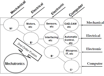
(22) Chapter 2 Tape Transport System Mechatronics Integration 2.1 Chapter Overview Minimizing lateral tape motion and regulating the tension applied to the travelling magnetic tape are key elements for enabling higher recording density and accuracy of high track-density magnetic tape drives. Among the modern tape drive products, flanged guides are commonly implemented in a tape path to limit lateral tape motion; tape tension is prescribed by actuating the dynamics of tape pack driving motors in an open loop control. A variety of advanced tape guiding mechanisms without the use of flanged guides have been developed to reduce lateral tape motion in industry and academia. However, these guiding mechanisms are likely to cause irregular tape tension changes and the aforementioned tape tension control technology does not have the ability to handle irregular tension changes. As a result, the tape tension cannot be maintained at a constant level. To avoid this, a closed loop controlled tape tension actuation is required. This chapter presents the development of a linear high track-density magnetic tape transport system that enables tape tension regulation by applying dynamic tape path alternation and friction guiding mechanisms during the tape transportation process using a closed loop controlled novel rotary guider. The development of this system is carried out based on a PDCA design cycle with mechatronics integration at design. Detailed steps of system development are described from both hardware and software aspects and include mechanical and electrical components design, software development, and computing of the technical issues of the developed system.. 2.2 Design Planning 2.2.1 Mechatronics Integration at Design Mechatronics integration at design is commonly applied to develop a system that involves mechanical, electrical, software, and computer engineering. Fig. 2.1 shows a diagram of mechatronics integration at design. One of the key advantages of this design method is that it introduces engineers to the over-thewall approach (Xu, 2009, p9). This approach allows different engineering fields such as mechanical engineering and electrical engineering to work concurrently and it enables a synergy between hardware and software integration (Xu, 2009, p9). Therefore, mechatronics design at integration is a highly valuable way to fluidly manage the design and development of mechatronics systems or products.. 2-1.
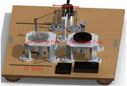
(23) Fig. 2.1: Mechatronics integration at design. (Retrieved from Xu, 2009, p4). 2.2.2 Design Cycle The tape transport system developed in this thesis involves both hardware and software. Applying the mechatronics integration to the design enables an efficient development of the system. Fig 2.2 shows how a design cycle of the tape transport system is applied to develop the system. This design cycle is formed by merging the Plan-Development-Study-Analysis (PDSA) design cycle and mechatronics integration. The mechatronics integration is applied during the development phase (D) in the PDSA cycle. The system is developed by cycling the four phases of PDSA. The process begins with the plan phase (P) in which the objectives and foundations of the system such as the key features and the required mechanical and electrical components, required software, time schedule of work, and resource management are decided. During the development phase, the hardware and software are developed in parallel work. Some of the engineering fields such as electrical and software engineering are related to each other. For example, the micro-control unit (electrical) and its operation driver (software) are deeply related each other; therefore, they should be developed concurrently. During the development phase, many works are done concurrently. After all components are developed, hardware and software are integrated and the operation of the system is tested and software is debugged as the Study phase. If any technical errors are detected, their causes are analysed and we return to the plan phase to start a new cycle.. 2-2.
(24) Fig. 2.2: PDCA design cycle of tape transport system.. 2.2.3 Development Planning The objective of this thesis is to develop a tape transport system that enables the travelling tape tension actuation in a closed loop control. Modern tape drive products that are available in the market control the tension by using the dynamics of tape pack driving motors in open loop control based on pre-calibrated laboratory results. However, to enable further improvement of tape performance, the thickness of the tape must be reduced. Thinner media presents a challenge though; it is more likely to have damage to its edges caused by impact on the flanges on guides that are commonly used to limit the LTM in modern tape drive products. A number of conventional tape guiding mechanisms that actuate LTM without relying on flanges on guides have been studied. However, those guiding mechanisms tend to interfere with the tape tension irregularly and current tape tension control technology is not able to handle such irregular tension changes. Therefore, a tape transport system that enables tape tension actuation in closed loop control is required to make feasible the new tape guiding mechanism. Hence, a prototype tape transport system as developed in this thesis needs to satisfy the following requirements.. 2-3.
(25) •. Actuate travelling tape tension in a closed loop in order to regulate the tension free from any disturbances.. •. Regulate the tape travelling speed.. •. Allow easy operation of system in order to carry out the experiment.. •. Provide feasible tension actuation with low cost.. In the beginning of the planning phase, the method used by the tension control mechanism and the core components of system such as tape pack driving sources and the sensor that measures the travelling tape tension are decided. The travelling tape tension is actuated applying surface friction guiding (Kartik, 2006). The surface friction guiding is accomplished by using the friction between the tape and the guide. A novel rotary guider that changes the amount of surface friction force between the tape and the guide by changing the wrap angle by rotating the rotary guider is proposed. Rotating the rotary guider also alters the tape path. Therefore, the tape path is dynamically altered during the tape transportation process. Brushed DC motors are employed as the driving source of tape packs due to their ease of actuation. DC motors are selected in order to transport tape over guides at a prescribed speed. A strain gauge is selected as the sensor that measures the tension by implementing it to the guide due to its high resolution, accuracy, and low unit cost. The next step is planning the design of mechanical components that are required to be manufactured. In this thesis, the tape transport system transports tape between two tape packs over the rotary guider and stationary guides. Therefore, the mechanical components that must be manufactured are the tape pack stands, the rotary guider, and stationary flanged guides. However, the mechanical components such as tape packs, ball bearing shafts of the tape pack, and flanged guides are taken from a HP commercial tape drive due to technical difficulty of manufacturing them. Other mechanical components are planned to be designed using a mechanical 3-dimensional computer-aided design (3D CAD) environment (SolidWorks 2009 SP4), and will be manufactured by the Massey University Albany Workshop. The last step of design planning is selection of the system’s control unit. The tape transport system requires several control elements such as the tension and motors. Therefore, multiple channels of pulse width modulation (PWM) and analogue-to-digital converters are essential. The processing speed of the control unit is another important factor for this system. For the aforementioned reasons, the Hitachi Renesas H8/3052f 16-bit micro control unit (MCU) based AKI H8/3052f is chosen as the brain of this system. For development of the tape system driver for MCU, the GCC Developer Lite (BestTechnology Co., Ltd., 2010) was selected as the development environment. To monitor and record output signal from the tension sensor, Windows HyperTerminal based GUI was selected and a serial communication line was established between MCU and GUI in order to enable real time communication. The GUI was also planned to be used to command the operations of systems. The system driving software required controls. 2-4.
(26) the operation of DC motors and rotary guider, sensor reading, and display of the measured tension on the GUI. Fig. 2.3 shows a 3D CAD initial mage of the planned tape transport system. This system was developed based on the design plan for this design phase.. Fig. 2.3: A 3D CAD image of designed tape transport system.. 2.3 Tape Transport System Overview A linear magnetic tape transport system was purposely developed in order to regulate tape tension during the transportation process in a closed loop control under standard laboratory conditions (25°C, 1atm). Fig. 2.4 shows the schematic of a developed tape transport system. The Linear Tape Open 4th generation (LTO4) standard magnetic tape is transported between the supply and take up packs, and over guides. The tension between guide B and C is regulated by a novel rotary guider that forms a part of the tape path in Fig2.4. The rotary guider is structured with a cylindrical flanged slider A, a cylindrical flanged guide B, and a rectangular rigid plate. The slider A and the guide B are mounted diagonally on each edge of a rigid plate.. The rigid plate is mounted on a DC servo motor and is able to rotate setting the guide B as a rotation centre with its workspace between 0º and 180º horizontally. The tension is generated from the surface friction force between the tape and the slider A of the rotary guider. Current tape tension is measured. 2-5.
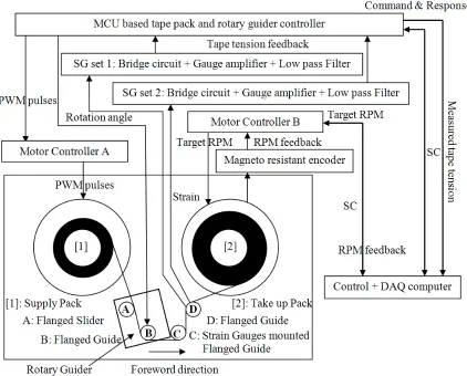
(27) using the strain gauge based tension sensor that is implemented in the guide C in Fig. 2.4. The rotary guider actuates the amount of surface friction force between the tape and the slider A by rotating the rotary guider based on the feedback from tension sensor. The tape transport operation is driven by the tape pack driving motors. Each tape pack is driven by a single high power brushed DC motor. The system has forward and backward capability with forward pass defined as being when the tape is transported from the supply pack [1] to the take up pack [2] in Fig. 2.4. The angular speed of the tape pack is controlled by a micro-control unit (MCU) based on a homemade DC motor controller A for the supply pack and the motor controller B for the take up pack. Both tape packs have a 44 mm inner diameter and a 98 mm diameter when the tape is fully loaded. The tape path is defined by a novel rotary guider and the flanged posts. The total length of the tape path is 640 mm initially, and it changes corresponding to rotation of the rotary guider. The tape tension is regulated when the tape is transported forward.. The reverse pass is only used to rewind the tape from the take up pack to the supply pack; the tape tension regulation is disabled during this process. The operations of the system, including the tape transportation and the rotary guider, are commanded by the control PC through Graphical User Interface (GUI). Serial Communication (SC) is established to communicate between PC and both motor controllers (MCUs). The measured tape tension by the tension sensor and the trajectory of the rotary guider angle are displayed on GUI and recorded on Data Acquisition (DAQ) PC in .txt file format. Fig. 2.5 and 2.6 show the apparatus of the developed tape transport system and a zoom-in view of the system including the connections of mechanical components, control units, and GUIs respectively. A complete list of components and instrumentation used in the system is summarized in Appendix A. The following sections separately describe the detailed technical designs of the tape transport system’s hardware and software. For the hardware development, the designs of tape pack stands, the rotary guider, the flanged guides, and the tension sensor are described. For the software development, descriptions of the control components of the system include the MCU and the motor controllers, the development of the tape transport system driver, GUI, and the serial communication line setting.. 2-6.
(28) Fig. 2.4: A laboratory test stands of tape transportation system.. 2-7.
(29) Fig. 2.5: Developed tape transport system apparatus.. Fig. 2.6: Zoom in view of magnetic tape transport system with connections of components and instrumentations.. 2-8.
(30) 2.4 Hardware Development Hardware of the tape transport system consists of the supply and takes up stands, a rotary guide, and stationary guides. This section describes in detail the technical design of mechanical components and assembly. The majority of mechanical components are designed in a 3D CAD environment and manufactured by Massey University Workshop Albany with top quality. Some of the components such as ball bearing shafts and tape packs are diverted from a commercial tape drive due to the technical difficulty of manufacture. The tension sensor including the bridge circuit, amplifier, filter, and the calibration of the sensor is also described. There are two elements needed to control this tape transport system: the tape travelling speed and the tension. The travelling speed of the tape is controlled by the tape stands; the tension is controlled by the rotary guider by dynamically alternating the tape path. 2.4.1 Tape Pack Stands The designs of tape pack stands, the supply stand, and the take up stand are described. The tape pack stands are structured using three mechanical components; a body, four legs, and four feet. The tape pack is fixed to the body using a ball bearing shaft that is diverted from the commercial tape drive. The ball bearing shaft is connected to a high power DC motor with a brass coupler. The speed and direction of the DC motor are controlled by a motor controller with micro controller pulse width modulation (PWM). In this system, the average travelling speed of tape is used since the angular speed of the tape pack in rpm is prescribed. The detailed explanations of travelling speed control, selection of DC motor, and the structures of both the supply and the take up stands are discussed in the following sections. (A) Tape Transport Speed Regulation The Linear Tape Open 4th generation (LTO4) standard magnetic tape is transported between the supply pack and the take up pack in this system. Both tape packs have a 44 mm inner diameter and a 98 mm diameter when the tape is fully loaded. The length of magnetic tape the supply pack contains is 820m. Fig. 2.7 shows both the supply and take up tape packs.. 2-9.
(31) Fig. 2.7: The supply and the take up pack.. The tape pack performs a circular motion and the travelling speed of tape changes in correspondence with the diameter of the tape pack with the fixed angular speed of the tape pack. A control algorithm such as robust servo control logic is essentially required to actuate the tape travelling speed as prescribed. However, in this developed tape transport system, the angular speed of the tape pack in RPMs is actuated, and the average tape travelling is taken as the tape travelling speed. Target angular speed RPMs are calculated based on the corresponding tape travelling speed when the remaining tape on the supply pack is at half-length, 410m. The radius of the empty tape pack “ ri ” is 22mm as shown in Fig 2.7. The total radius when the remaining tape length on the supply pack is half-length is calculated as 37.975mm; the number of tape wraps “W” is 2176. Total tape thickness “h” including the gap between adjacent tapes is 7.34µm. Equation (1) calculates the target angular speed of the tape pack in rpms from the corresponding tape travelling speed v (m/s). Substituting corresponding parameters to equation (1), equation (2) is obtained. Table 2.1 summaries the target tape travelling speed and corresponding target RPM. Fig. 2.8 shows the transition of actual tape travelling speed in the function of length of tape transported.. RPM =. 30v - (1) (ri + hW )π. Where RPM is target angular speed (rpm), v is target tape average travelling speed (m/s),. ri is inner radius of empty. tape pack (m), h is total thickness of the tape (m), and W is number of tape wraps of the supply pack.. 2-10.
(32) RPM = 251v - (2) Where PRM is target angular speed of tape (rpm), v is target tape average travelling speed (m/s).. target tape transport speed 1m/s 2m/s 3m/s 4m/s 5m/s 6m/s 7m/s. Target RPM of tape pack (With 3:1 gear head) 251 (753) 502 (1506) 753 (2259) 1004 (3012) 1255 (3765) 1506 (4518) 1757 (5271). Table 2.1: Target angular speeds of tape pack and corresponding travelling tape speeds.. Fig. 2.8: Transition of travelling tape speeds.. The DC motor that drives the tape pack is selected using the calculated results above and the following requirements: • Minimum RPM requirement of DC motor is 1757rpm (5271rpm). • Minimum torque requirement of DC motor is 120mNm. • Encoder is required to actuate rpm of DC motor as prescribed angular speed. • GUI based operation of DC motor. The maximum rpm of the DC motor is required to be faster than 1757 rpm that corresponds to the average tape travelling speed 7m/s in Table 2.1. In modern tape drive products, 7m/s is the common transportation. 2-11.
(33) speed of fast-forward. Therefore, the developed tape system requires enabling a faster than 7 m/s of maximum tape travelling speed. From Nagao and Chang, the required minimum DC motor’s torque that enables tape travelling speed at 7m/s is approximately 40 mNm (Nagao & Chang, 2009). In this system, tension is regulated using friction guiding with the rotary guider. Therefore, the minimum tongue requirement can be larger than 40 mNm. Taking the safety factor by 3, the minimum torque requirement is set at 120mNm in order to avoid a stall of the DC motor during the transportation. Since the angular speed of the tape pack is actuated in closed loop, an encoder is essentially required to measure the current rpm of motor as feedback. The Maxon RE35 Graphite Brushed DC motor with a 3.1 ratio permanent gear head and a 10-bit magnet resistant encoder was chosen as the driving motor for the tape pack. This motor was chosen as a way to become familiar with the Maxon motor products, and was applied to one side of the tape pack stand, the take up pack, to save the cost of tape transport system development. Therefore, for the other side of the tape pack stand, the supply pack, a direct drive 6V high power DC motor was applied. Hence, in this developed tape transport system, tape tension regulation is enabled during the forward pass when the tape is transported from the supply pack to the take up pack, and disabled when the reverses pass. The reverse pass is used to rewind the tape to the supply pack; the tape speed regulation is also disabled during the reverse pass. Further, during the transportation process, both motors are connected to the tape pack. However, only one of the motors corresponding to the direction of transportation is operated. The maximum torque of Maxon DC motor is 77.7mNm and the 3:1 ratio gear head triples the torque of the motor. Therefore, the actual target RPM is three times larger than the calculated rpm in table 2.1. The maximum rpm of the Maxon motor is 7070rpm. The motor satisfies the minimum rpm and torque requirement for the tape pack driving motor. Parameters such as the prescribed rpm and operations of motor are able to be controlled by the Maxon motor control GUI through a motor controller which is described later in this chapter. (B) Tape Supply Stand The tape supply stand is structured with an aluminium rigid plate, four cube legs, and another four feet. The summary of mechanical components of the supply pack stand and a photographic image of the developed supply stand are shown in Table 2.2 and Fig. 2.9 (a) respectively. The tape pack and the ball bearing shaft that links the tape pack and the driving DC motor are diverted by a commercial tape drive due to the technical difficulty of manufacturing. A schematic of the supply stand is shown in Fig. 2.9 (b). The driving source of the supply stand is a 6V high power brushed DC motor; the tape pack and the motor are connected by a ball bearing shaft in Fig. 2.9 (b) in order to reduce the excitation of the DC motor. The ball bearing shaft and the motor are linked by a brass coupler. The motor is driven by angular. 2-12.
(34) speed micro-controller pulse width modulation (PWM) generated by a homemade motor controller formed by the MCU and the motor controller A (Parallax HB-25) that are described later in this chapter.. Tape Pack Stand Ball Bearing Shaft Coupler Driving Source Supply Pack. DC_Motor_Base: DWG No 1 (Appendix B) × 1 DC_Motor_Leg: DWG No 2 (Appendix B) × 4 DC_Motor_Foot: DWG No 3 (Appendix B) × 4 Diverted from a HP Commercial Tape Drive × 1 Brass made 6mm to 6mm Female Coupler × 1 6V High Power DC Motor × 1 Quantum LTO4 Tape Cartridge × 1. Table 2.2: Mechanical components of the supply stand.. (a). (b). Fig. 2.9: A screenshot (a) and a schematic (b) of supply stand.. (C) Tape Take up Stand The structure of the take up stand is the same as the supply stand. Table 2.3 shows the mechanical components that structure the take up stand, and Fig. 2.10 shows a photographic image and schematic of the take up stand. The take up pack is driven by a Maxon RE35 90W Graphite Brushed DC motor with a 3:1 ratio permanent gear head in order to increase the torque of the motor. A 10 bit Maxon magnet resistant encoder is also used in the motor to measure the angular speed of the motor in rpms. The motor is operated by a Maxon EPOS2 24/ 5 Digital motor controller and the angular speed of motor is controlled as prescribed based on the feedback from the encoder. Detailed descriptions of the motor controller and its operations are discussed in the descriptions of software development.. 2-13.
(35) Tape Pack Stand Ball Bearing Shaft Coupler Driving Source Gear Head Encoder Take up Pack. DC_Motor_Base: DWG No 1 (Appendix B) × 1 DC_Motor_Leg: DWG No 2 (Appendix B) × 4 DC_Motor_Foot: DWG No 3 (Appendix B) × 4 Diverted from a HP Commercial Tape Drive × 1 Brass made 6mm to 6mm Female Coupler × 1 Maxon RE 35 DC Coreless Motor × 1 3:1 ratio Permanent Gear Head × 1 Maxon 10bit Magnet Resistant Encoder × 1 Diverted from a HP Commercial Tape Drive × 1 Table 2.3: Mechanical components of take up stand.. (a). (b). Fig. 2.10: A screenshot (a) and a schematic (b) of take up stand.. 2.4.2 The Rotary Guider The rotary guider is structured with a cylindrical flanged slider A, a cylindrical flanged guide B, and a rectangular rigid plate. The slider A and the guide B are mounted diagonally on each edge of the rigid plate. The rigid plate is mounted on a DC servo motor and is able to rotate; this sets the guide B as a rotation centre with its workspace between 0º and 180º horizontally. The diameter of both flanged slider A and flanged guider B are 10mm. The span between the flanged slider A and the flanged guide B is 100mm. A summary of the mechanical components used for the structure, a photographic image of, and a schematic of the rotary guider are shown in Table 2.4, Fig.2.11, and Fig. 2.12 respectively. The tension is. 2-14.
(36) generated by the surface friction force between the tape and the slider A of the rotary guider in Fig. 2.11. The rotary guider actuates the amount of surface friction force between the tape and the slider A by rotating the rotary guider based on feedback from the tension sensor that is described in the next section. The DC servo motor is connected to the micro-control-unit-based homemade rotary guider controller which also drives the supply pack driving the DC motor, and rotates the guider using a PWM signal from the controller. Fig. 2.13 shows screenshots of the rotary guider with rotation angles of 0°, 20°, and 40° when the case of tape pack diameter is 96mm and 50mm.. Rotary Guider Flanged Slider A Flanged Guide B Driving Source. Rigid Plate (TAMIYA Universal Plate) × 1 Probe_Holder_Base: DWG No 7 (Appendix B) × 1 Servo_Motor_Holder: DWG No 9 (Appendix B) × 1 Diverted from a HP Commercial Tape Drive × 1 Diverted from a HP Commercial Tape Drive × 1 5V Parallax Standard Servo Motor × 1 Table 2.4: Mechanical components of rotary guider.. Fig. 2.11: A photographic image of developed rotary guider.. 2-15.
(37) Fig. 2.12: A schematic of rotary guider.. 2-16.
(38) Fig. 2.13: Screenshots of rotation of rotary guider with rotation angle (a) 0°, (b) 20°, and (c) 40°.. 2-17.
(39) 2.4.3 Stationary Flanged Guide The stationary flanged guide is structured with an aluminium body, a leg, and a rotatable cylindrical flanged guide that is diverted from the HP commercial tape drive. Table 2.5 below shows the mechanical components that are used to form a stationary flanged guide. Fig. 2.14 shows photographic images of flanged guides C and D. Flanged guide C is used to measure the tension, and tension sensor that is discussed in the next section are attached. Extra flanges were added to flanged guide D in order to prevent misalignment with the tape path. Stationary Guide Flanged Guide C & D. Guide_Pole: DWG No 5 (Appendix B) × 2 Guide_Pole_Leg: DWG No 6 (Appendix B) × 2 Diverted from a HP Commercial Tape Drive × 2. Table 2.5: Mechanical components of stationary guide.. (a). (b). Fig. 2.14: Photographic image of stationary guides (a) flanged guide C and (b) flanged guide D.. 2-18.
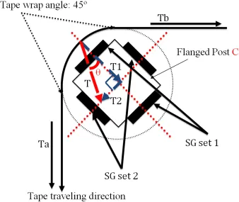
(40) 2.4.4 Tension Sensor In order to regulate the travelling tape tension, measuring current tape tension is essential. The developed magnetic tape drive system was designed to regulate travelling magnetic tape tension between guide posts B and C where the read/write head is normally placed in the tape drive products. This is shown in Fig. 2.4. Tape tension is measured by two sets of 2-active-gauge method employed strain gauges based tape tension sensors that are implemented on the guide post C in Fig. 2.4. A close up schematic of tape tension sensors is shown in Fig. 2.15. Each strain gauge set (Kyowa KFG-5-350-C1-11) is connected to the bridge circuit (Wheatstone bridge), and the output signal is amplified by the gauge amplifier with a gain of 1000 (BB INA101 High Accuracy Instrumentation Amplifier), then the amplified signal is conditioned by a 1Hz low pass filter. Finally, the signal is sent to the rotary guider controller (MCU) and goes through an analogue to digital conversion process. An electric circuit diagram and photographic images of the bridge circuit, amplifier, and low pass filter and are shown in Fig. 2.16 and 2.17 respectively. Fig. 2.18 shows a top view schematic of SG sets 1 and 2, and the applied load vector of each SG set. In a case where tape motion is static, tape tension Ta and Tb shown in Fig. 2.18 are equal amounts and the load “T” applied to flanged post “C” is on the axis of “T1” with θ as 0°. However, since magnetic tape is travelling, the strains on the pole that are measured by strain gauges are dynamic strain and the angle of axis of load “T” θ is changed depending on the difference between Ta and Tb; therefore, in order to measure tape tension accurately, the strain gauges must be placed on the axis of load “T”. Hence, travelling tape tension is measured by using two sets of strain gauges. Load “T” is calculated by equation (3) using SG set 1 “T1” and SG set 2 “T2” as its elements.. T = T 12 + T 22 - (3) (Where T is the load applied to the guide (N) and T1 & T2 are elements of T (N).) Tape tension is calculated based on measured load “T”. Since tape travelling direction is as shown in Fig. 2.18 below, the relationship between Ta and Tb must be Ta > Tb, and tape wrap angle is fixed at 45º, the angle of load “F” θ is located between 0° ≤ θ ≤ 45°. Further 2-active-gauge method is applied in order to double the signal strength.. 2-19.
(41) Tension Sensor Wheatstone Bridge Instrumentation Amplifier. Low pass Filter. Strain Gauge (Kyowa KFG-5-350-C1-11 (350Ω)) × 4 350Ω Resister × 4 BB INA101 High Accuracy Instrumentation Amplifier × 2 100KΩ Pot Resister × 2 10KΩ Variable Resister (40 Ω) × 2 0.1µF Capacitor × 2 1.6KΩ Resister × 2 100µF Capacitor × 2. Table 2.6: Electrical components of tension sensor.. (a). (b). Fig. 2.15: A screenshot (a) and schematic (b) of strain gauges based tension sensors.. 2-20.
(42) Fig. 2.16: A circuit diagram of bridge circuit and amplifier.. Fig. 2.17: Photographic images of developed bridge circuits, amplifiers, and low pass filters.. 2-21.
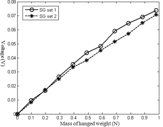
(43) Fig. 2.18: A top view schematic of tension sensor placements.. (A) Strain Gauges Calibration In order to convert outputs from strain gauges based tape tension sensors to tape tension, the calibration of sensors is required. Fig. 2.19 shows a photographic image and a schematic of the strain gauges calibration stand. This calibration is carried out with static tape motion. A certain length of magnetic tape is fixed on the rigid stationary wall and a weight is hung on the other side of the tape. The weight is initially 0g, and then it is increased by 10g up to 100g. One of the strain gauge set is attached on the axis of resultant force created by tension Ta and Tb with angle Rθ as 45°; a measured strain is created by the load “T1” (“T2”) as shown in Fig. 2.18. The output voltage of strain gauges with each weight is recorded. The calibration of. the. other. strain. gauge. set. is. also. carried. out. with. the. same. procedure.. Fig. 2.20 shows the calibrated functions of both strain gauge sets with the relationship between output voltage of strain gauge (V) and weight (N). Both calibrated functions display linear characteristics. The gradient of each function is obtained by taking fitted curve; 0.0738 for SG set 1 and 0.0708 for SG set 2. The conversion equations of both SG set 1 and 2 from strain gauge output to load applied is shown in equation (4) and (5) respectively. “T1” and “T2” measure the load applied to flanged post C that is same. 2-22.
(44) as tape tension. Therefore, from equation (3), the calculated load applied to flanged post C “T” in Fig. 2.18 equals the tape tension. Hence, tape tension is mentioned as “T” in the following sections.. Fig. 2.19: A screenshot (a) and schematic (b) of tension sensor calibration stand.. Fig. 2.20: Calibrated functions of both tension sensors SG set 1 and 2.. T1 =. V1 - (4) 0.0738. T2 =. V2 - (5) 0.0708. (Where T1 (T2) is load applied to strain gauge set 1 (2) (N) and V1 (V2) is voltage out form strain gauge set 1 (2) (V).). 2-23.
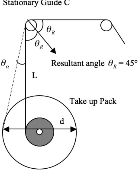
(45) (B) Wrap Angle The wrap angle of the stationary post increases as tape is transported due to an increase in the diameter of tape take pack up as shown in Fig. 2.21. In order to apply the calibrated results obtained in the previous section, the wrap angle of stationary guide C 2θ R must be maintained at 90°. However, the wrap angle. 2θ R increases up to θα corresponding to the diameter of take up pack D as shown in Fig. 2.21. Therefore, it is essential to insert an extra stationary guide between the stationary guide C and the take up pack in order to maintain the wrap angle of statuary guide C at constant. An extra stationary guide D is inserted in the tape path, and Fig. 2.22 shows a photographic image of the extra stationary guide D.. Fig. 2.21: A schematic of wrap angle change around stationary guide C.. 2-24.
(46) Fig. 2.22: A photographic image of extra stationary guide D.. 2-25.
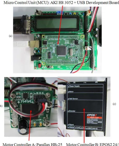
(47) 2.5 Software Development In this section, development of control units, the system driving software, and control GUI are described including connections of control units and control GUI. The tape transport system driver was developed in order to control elements of the developed system. 2.5.1 Control Elements, Instrumentations, and Software Development Environment The developed tape transport system is required to control the following elements: • Control the tape pack driving DC motor. • Measure tape tension. • Control rotation of rotary guider based on measured tape tension. • Display logs and record measured tension and trajectory for rotary guider. Table 2.7 below lists a control unit, motor controllers; software including GUIs are used to control the operations of tape transportation. The operations of the tape system are controlled by a micro-control unit (MCU). AKI H8/3052f that was chosen as a MCU for the developed tape system. AKI USB development board for the MCU is used in order to establish the serial communication line between MCU and the control PC. Both tape pack driving motors are controlled by a motor controller. The driving motor of the supply pack is controlled by a Parallax HB-25 motor controller, while the driving motor of the take up pack is driven using a Maxon EPOS2 24/5 digital motor controller. Operations of the system are commanded by the control PC through operation GUI. In this developed system, the forward pass operations are commanded by the EPOS Studio motor control GUI (Maxon motor ag, 2010); other operations such as control of rotary guider, tension measurement, and rewind operation of tape are commanded by a Windows HyperTerminal Based control GUI. Fig. 2.23 shows photographic images of the MCU and both motor controller A and B are shown in Fig. 2.4. Technical specifications of control components are listed in Appendix A. Micro Control Unit MCU Motor Controller A Motor Controller B Development Software GUI. AKI-H8/3052f with USB Development Board × 1 Parallax HB 25 Motor Controller × 1 Maxon EPOS 2 24/5 Digital Motor Controller × 1 Best Technology Inc GCC Developer Lite Ver2.36 × 1 Windows Hyper Terminal × 1 EPOS Studio Ver1.41 × 1. Table 2.7: A list of control components, instrumentations and GUIs.. 2-26.
(48) Fig. 2.23: Screenshots of (a) 16 bit micro control unit (MCU) with USB development board, (b) the motor controller A, and (c) the motor controller B.. The tape transport driving software for MCU was developed using C++ programming language in GCC Developer Lite Ver. 2.36 (BestTechnology Co., Ltd., 2010) environment. Fig. 2.24 shows a screenshot of the developing environment. Full program codes of the developed tape transport system drive are shown in appendix C.. 2-27.
(49) Fig. 2.24: A screenshot of GCC Developer Lite developing environment. (BestTechnology CO., LTD., 2010). 2.5.2 The Tack up Stand Control The take up pack is driven by a Maxon DC motor; the operation of the motor is controlled by an EPOS Studio graphical user interface (GUI) (Maxon motor ag, 2010) on a control PC through a motor controller (Maxon EPOS2 24/5). Fig. 2.25 shows connections between the controls PC (GUI), the motor controller, and DC motor. The operator inputs desired angular speed of motor in rpm with acceleration and declaration gain in rpm/sec. Motor controller controls the motor’s rpm as desired by sending PWM signals to the motor based on the feedback encoder implemented within the motor. Measured rpm is also displayed on GUI as shown in Fig. 2.25.. 2-28.
(50) Fig. 2.25: A connection flowchart of the take up stand.. 2.5.3 The Rotary Guider and the Supply Pack Control AKI H8/3052f MCU control the operation of the tape supply pack driving motor and measures the travelling tape tension using the tension sensor. It then controls the rotary guider based on the measured tape tension. The driving motor for the supply pack is controlled by PWM of MCU and HB 25 motor controller. The motor controller amplifies the PWM signal generated from PWM port channel 1 of MCU to a stronger signal to drive the motor. Both measured analogue tension signal SG sets 1 and 2 are sent to the analogue-to-digital converter port channels 1 and 2 respectively and converted to digital signals. The resolution of the analogue signal is 10bit (1024). The converted digital signal is processed to calculate total tension within the MCU, and PWM port channel 2 sends a signal to the rotary guider to rotate the angle to regulate the tension. The operation of the system is commanded by the Windows Hyper Terminal based control GUI by establishing the serial communication line between the MCU and the control PC. MCU also replays responses to commands such as display the measured tape tension from both tension. 2-29.
(51) sensors; the current angle of rotary guider from control GUI. Fig. 2.26 illustrates the connections between MCU and other control components.. Fig. 2.26: A connection flowchart of the supply stand and rotary guider.. Fig. 2.27 shows the flowchart of the developed control GUI based on Windows Hyper Terminal. The control GUI initially opens up when the main menu is booted. To command the system, an operator chooses a mode from selections of automatic mode, manual mode, and rewinding mode. Automatic mode enables the tape tension regulation with dynamic tape path alternation. Manual mode enables the manual control of the rotary guider. Rewinding mode enables the reverse pass operation of tape transport. To enable each mode, input from a corresponding key is. For example, to enable Automatic Mode, pressing the 1 on the keyboard of the control PC.. 2-30.
Figure

+7


Related documents
from a technical mixture with higher degree of chlorination to a technical mixture with lower degree of chlorination over this time period, (2) early, industrial, or combustion
The objective of this study was to develop Fourier transform infrared (FTIR) spectroscopy in combination with multivariate calibration of partial least square (PLS) and
Standardization of herbal raw drugs include passport data of raw plant drugs, botanical authentification, microscopic & molecular examination, identification of
The degree of resistance exhibited after 1, 10 and 20 subcultures in broth in the absence of strepto- mycin was tested by comparing the number of colonies which grew from the
Henderson (301) 229-7187, All Rights Reserved RACF is, of Course.. • IBM’s Resource Access Control Facility, the Software
This study proposed a systematic grounded theory approach to discover if students became motivated for reading by being given an opportunity to select reading content for
If unresponsive and breathing is adequate, place the casualty in a stable side position When you move the casualty, immobilise the casualty by supporting the head and neck
4b (again, vehicle icons are not drawn to scale). This area was approximately 2. We analyzed scenarios with different vehicle densities per square kilometer, as specified in Table
