Urkund Analysis Result
Analysed Document: AMALOR.pdf (D45620328)
Submitted: 12/12/2018 2:57:00 PM
Submitted By: amalor.dr@gmail.com
Significance: 4 %
Sources included in the report:
jerry final pdf.pdf (D34365953) bindal thesis.pdf (D41881235)ceramic dental biomaterial.pdf (D26547752) bharat thsis (prostho).pdf (D31245018)
https://www.ncbi.nlm.nih.gov/pubmed/25126621
https://www.sciencedirect.com/science/article/pii/S0022391317305553 https://www.jove.com/visualize?author=Ender+Kazazoglu
https://juniperpublishers.com/adoh/ADOH.MS.ID.555581.php
https://pdfs.semanticscholar.org/04ef/49226ee35dca9b0af1e24c4bbb76ab136350.pdf
Instances where selected sources appear:
17
ACKNOWLEDGEMENT
“Satisfaction and Euphoria that accompany the successful completion of any task would be incomplete without mentioning the people who made it possible and support had been a constant source of encouragement which crowned our efforts with success”
“Always let God lead you, and He will clear the road for you to follow.”
First and foremost, I would like to thank God Almighty for giving me the strength,
knowledge, ability and opportunity to undertake this research study. Thank you for giving
me support especially during all the challenging moments in completing this thesis by overcoming the adversity, to do what’s right for the benefit of the greater good, to rise
above the negativity. I am truly grateful for your exceptional love and grace during this
entire journey .
I have no words to express my sincere thanks and gratitude to Dr. T. Sreelal MDS, Professor and Head of the Department of Prosthodontics, Sree Mookambika Institute of
Dental Sciences, Kulasekharam, who gave constant encouragement and wholehearted
support at all stages of this research work. I greatfully acknowledge the inspiring guidance,
pregmatic suggestions and excellent hospitality. I don’t know how could I repay your effort
and inspiration towards me to do my best. I found guidance, mentor, discipline and friendship everything in one person and I am proud and grateful to be your student. Thank you for challenging me to be my best and instilling in me a passion for learning. My heart
dedication and effort. I hereby extend my deepest gratitude to; who gave me the freedom
to explore on my own and at the same time the guidance to recover when my steps faulted.
I take pride in acknowledging the insightful guidance by promoting my confidence level
and being there at times when I required motivation and propelling me on the course of
this thesis. Alexander, The Great, once said, “I am indebted to my father for living, but
I am indebted to my teacher for living well.” I could not have imagined for having a better advisor and mentor for my study. The confidence begins, most of the time, with a
mentor who believes in you, who tugs and pushes and leads you on to the next plateau. I
thank him from the bottom of my heart for his time, patience and unyielding faith in me
for promoting my confidence. I also thank him for making Prosthodontics an interesting
subject in his own unique style. He also shared his pearls of wisdom with me during the
course of my post graduate curriculum. Sir, you are the best person , guide and mentor in
this world. Wherever I may go in my life, I will always remember that I had an excellent guide for a lifetime .I have been amazingly fortunate to get the opportunity to study under his guidance. I thank him for his time to listen to my concerns, guide me on the path to knowledge, and reassure me for the minute details throughout this dissertation. ‘Curiosity is the mother of innovation’, with all the gratitude that I feel and warm regards that I can
muster, I thank you sir for planting a seed of curiosity and igniting my imagination for me
to be able to flourish and succeed.
I am extremely grateful to Dr. Aparna Mohan MDS, Reader, , my co-guide, for her everlasting support, source of love, affection and care. She always extended her ever
helping hand during times of hurdles, who with her charming smile melts away my
by providing me with articles needed for my dissertation. She acted as a strong pillar of
support who inspite of her own hectic schedule found time in correcting this dissertation.
She always guided me to the light of knowledge with her valuable guidance, suggestions
and tireless pursuit for perfection. She has a strong personality and a heart full of affection
which helped me to pass the tough times during my post graduate programme.
I am deeply indebted to Dr.Giri Chandramohan, MDS, Reader, who with his vast knowledge helped me in my work theoretically as well as clinically. He is a person with
lots of clinical and laboratory knowledge and at the same time he is very helpful and trustful
person who his pure at heart . He guided me with direction and technical support and
provided knowledge about many innovative approaches in prosthodontics. Being nice,
friendly he has persuaded me to develop my presentation skill and to perform better in a
large podium.
I also extend my gratitude to Dr.Allen Jim Hines MDS, Senior Lecturer, who is always approachable for any help and he is the one who taught me how to manage anxious
and apprehensive patients with his unique style and getting us out of trouble.
I express my sincere gratitude to Dr. Vivek B Chandran MDS and Dr.Soumya Mohan MDS Senior Lecturer, during my postgraduate life, first as my senior and as a good friend and now as a staff. They provided me moral support and became a friend for
exchanging his knowledge and skills during my post graduate programme, which helped
I express my heartfelt and sincere thanks to Dr.A.Anuroopa MDS, Reader and
Dr.James Rex (Reader)for their valuable help and guidance.
I express my sincere thanks to Dr.Elizabeth Koshi MDS, Principal, Sree Mookambika Institute of Dental Sciences, Kulashekaram for allowing me to utilize the
clinical material and facilities for the completion of this dissertation.
I extend my profound gratitude to Dr.Prasanth Solanki for determining the sample size for my study and to Mr.Porchelvan, Statistician, for helping me in untying various knots of statistics and solving the riddles in it, thereby working out proper results that made
my thesis an unadulterated one.
This endeavour would have been impossible without the help, guidance and
inspiration of Mr.Viswanathan, Scientist in charge of FSEM Laboratory and Mr.NS Nandha Gopal Scientist in charge of Stereomicroscopic studies, Nanotechnology department , Sathyabama University , chennai.
It gives me an immense pleasure to thank Dr.Jithin GN, my co-PG, who has been with me throughout my postgraduate life like an elder brother, guiding and encouraging
me during the happy and hard moments making this journey a memorable one. Thank you
for being brother as well as friend who’s there when I need him, someone who picks me
up when I fall, a person who sticks up for me when no one else will. .He is the one who
made me understand that Keeping together is progress and Working together is success .
During the most difficult times when writing this thesis, he gave me the moral support and
This acknowledgement seems lacking without the mention of my dear seniors
Dr.Rajkumar, Dr.Vivek B Chandran , Dr. Ebinu A, Dr.Soumya Mohan and my dear
fellow Post graduates Dr.Ponjayanthi, Dr.Femin David, Dr.Claudia Peter and Dr.Harshini their constant support, motivation and encouragement when I slow down.In
my daily work, I have been blessed with a friendly and cheerful group of fellow
postgraduates.
I am also thankful to Mr.Bibin Sekhar,Mr. Allen technician and ceramist SMIDS and to Mrs.Anitha, Mrs.Sunitha , Mrs.Jayalekshmi and Mrs.Viji Kumari Assistants, Department of Prosthodontics, SMIDS a lot all through my three years of Post Graduate
life.
I am thankful to Mr.Srinivasan, Mrs.Jeyalakshmi Srinivasan Office staffs, SMIDS for their sincere work throughout my three years of postgraduate life.
The success of this study required the help of various individuals, but without the
support and love of my family, I could not have met their objectives in doing this study. A
wave of fond emotions sweep over me as I struggle to gather the appropriate words, to
express the insurmontable respect and warm gratitude I feel for my father P.Valluvan, my Mother V.Arokia Mary , my younger sister Angel grace for their confidencein me and their sacrifices, strength and encouragement at all times. They are always my inspiration
and is solely responsible for refurbishing my life and profession.
when I needed them the most. They were more like a family to me apart from being my
postgraduate buddies.
Finally, a huge thank-you to everyone who has been a part of my life directly or
indirectly supported and prayed for me along the way.
“Thank you God for the gift of the life, I also thank you for the gift of wonderful people I have met along this journey. Some of them inspire me, stretch me, challenge me, love me and encourage me .All of them helped me to realise how meaningful and beautiful my life is. Bless them lord with good health, security, wealth, success, grant their prayers, peace and joy”
Thank you all….
SPECIAL ACKNOWLEDGEMENT
I take this opportunity to thank specially our Chairman
Dr.C.K.VELAYUTHAN NAIR M.S, Sree Mookambika Institute of Dental Sciences, our Director Dr.REMA V NAIR M.D, Sree Mookambika Institute of Dental Sciences and our Trustees Dr.R.V.MOOKAMBIKA M.D,DM ,
Dr.VINU GOPINATH M.S,MCH and Mr.J.S.PRASAD for giving me the opportunity to utilize the facilities available in this institution for conducting this
CONTENTS IN CONCISE
SL.No INDEX
1 LIST OF ABBREVIATIONS 2 LIST OF FIGURES
3 LIST OF TABLES
4 LIST OF GRAPHIC DIAGRAMS 5 ABSTRACT
6 INTRODUCTION
7 AIMS AND OBJECTIVES 8 REVIEW OF LITERATURE
9 MATERIALS AND METHODOLOGY 10 RESULTS AND OBSERVATIONS
11 SCANNING ELECTRON MICROSCOPIC ANALYSIS 12 STEREOMICROSCOPIC ANALYSIS
13 DISCUSSION
CONTENTS
SL.No INDEX PAGE
1 ABSTRACT 1-4
2 INTRODUCTION 5-10
3 AIMS AND OBJECTIVES 11
4 REVIEW OF LITERATURE 12-27
5 MATERIALS AND METHODOLOGY 28-35
6 RESULTS AND OBSERVATIONS 36- 44
7 SCANNING ELECTRON MICROSCOPIC ANALYSIS
45-46
8 STEREOMICROSCOPIC ANALYSIS 47-48
9 DISCUSSION 49-54
LIST OF ABBREVIATIONS
ANOVA Analysis of Variance
PEEK Polyetherether ketone
FESEM Field Emission Scanning Electron Microscope
FPD Fixed partial denture
ZrO2 Zirconium dioxide
CAD Computer aided design
CAM Computer aided manufacturing
Y-TZP Yttria-stabilized zirconia
PMMA Polymethyl methacrylate
LIST OF FIGURES
Figure 1 PREPARED NATURAL 1st PREMOLAR
Figure 2 PREPARED NATURAL 1st PREMOLAR
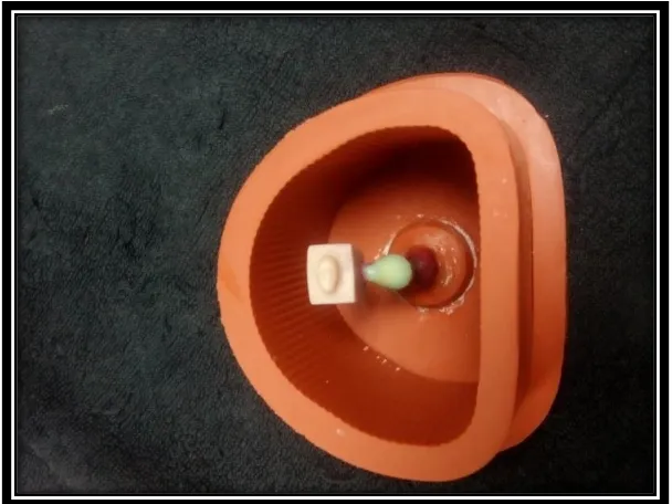
Figure 3 WAX PREPARATION- PATTERNED FOR MASTER DIE
Figure 4 WAX PREPARATION- PATTERNED ATTACHED TO THE
SPRUE FORMER
Figure 5 CASTING RING
Figure 6 COBALT-CHORIMIUM TOOTH MODEL
Figure 7 HEAT CURE ACRYLIC TOOTH MODELS (30 No’s)
Figure 8 PEEK COPING (15.No.s)
Figure 9 ZIRCONIA (15.No.s)
Figure 10 SELF ADHESIVE RESIN LUTING CEMENT
Figure 11 LUTED ZIRCONIA COPINGS
Figure 12 LUTED PEEK COPINGS
Figure 13 DIAMOND WHEEL BURS
Figure 14 SECTIONING OF SAMPLES – (RAY FOSTER, USA).
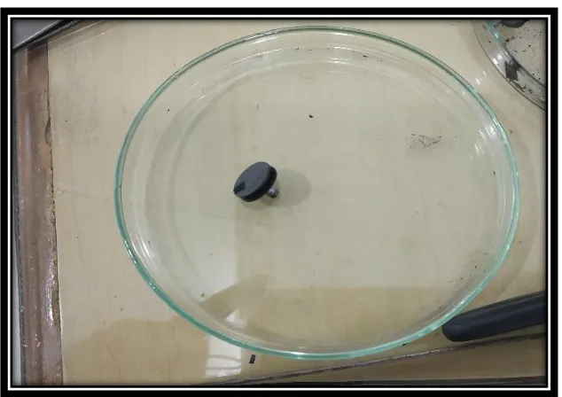
Figure 16 PREPARED SAMPLE
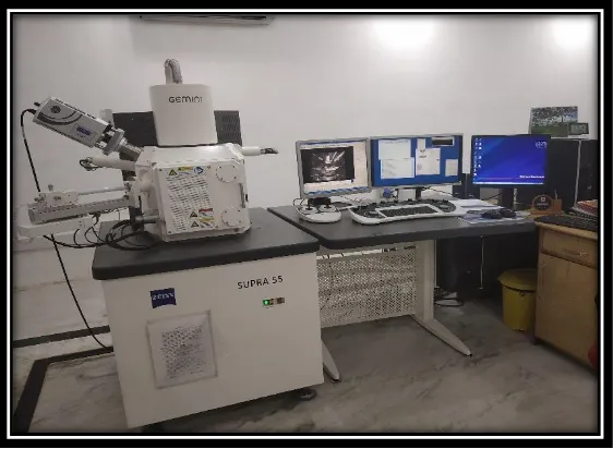
Figure 17 FIELD EMISSION SCANNING ELECTRON MICROSCOPE (SUPRA 55)
Figure 18 SPUTTERING COTTER (ION SPUTTER)
Figure 19 SPUTTERING WITH GOLD & PALLAIDIUM
Figure 20 SAMPLE STEM
Figure 21 CARBON TAPE
Figure 22 FESEM – COOLER DEVICE
Figure 23 BEFORE PLACING SAMPLES – COMPUTER MONITOR
Figure 24 SAMPLES IN SAMPLE HOLDER
Figure 25 INNER VIEW- FIELD SCANNING ELECTRON MICROSCOPE
Figure 26 SAMPLES IN SAMPLE HOLDER- FSEM
Figure 27 SAMPLES PLACED
Figure 28 VIEW OF SAMPLES- COMPUTER MONITOR
Figure 29 STEREO MICROSCOPE( LEICA M125C)
Figure 30 SAMPLES IN THE SLIDE
Figure 31 AIROTOR
Figure 32 CASTING MACHINE
Figure 34 FIELD EMISSION SCANNING ELECTRON MICROSCOPE IMAGE SHOWING MARGINAL GAP IN MESIAL REGION (a) OF GROUP I PEEK COPING
Figure 35 FIELD EMISSION SCANNING ELECTRON MICROSCOPE
IMAGE SHOWING MARGINAL GAP IN DISTAL REGION (b) OF GROUP I PEEK COPING
Figure 36 FIELD EMISSION SCANNING ELECTRON MICROSCOPE
IMAGE SHOWING INTERNAL GAP IN AXIAL REGION (c) OF GROUP I PEEK COPING
Figure 37 FIELD EMISSION SCANNING ELECTRON MICROSCOPE
IMAGE SHOWING INTERNAL GAP IN BUCCAL CUSP (d) OF GROUP I PEEK COPING
Figure 38 FIELD EMISSION SCANNING ELECTRON MICROSCOPE
IMAGE SHOWING INTERNAL GAP IN FOSSA (e) OF GROUP I PEEK COPING
Figure 39 FIELD EMISSION SCANNING ELECTRON MICROSCOPE
IMAGE SHOWING INTERNAL GAP IN LINGUAL CUSP (f) OF GROUP I PEEK COPING
Figure 40 FIELD EMISSION SCANNING ELECTRON MICROSCOPE
IMAGE SHOWING INTERNAL GAP IN AXIAL (g) OF GROUP I PEEK COPING
Figure 41 FIELD EMISSION SCANNING ELECTRON MICROSCOPE
Figure 42 FIELD EMISSION SCANNING ELECTRON MICROSCOPE IMAGE SHOWING MARGINAL GAP IN DISTAL REGION (b) AND AXIAL REGION (g) OF GROUP II ZIRCONIA
Figure 43 FIELD EMISSION SCANNING ELECTRON MICROSCOPE
IMAGE SHOWING INTERNAL GAP IN AXIAL REGION (c) OF GROUP II ZIRCONIA COPING
Figure 44 FIELD EMISSION SCANNING ELECTRON MICROSCOPE IMAGE SHOWING INTERNAL GAP IN BUCCAL CUSP (d) OF GROUP II ZIRCONIA COPING
Figure 45 FIELD EMISSION SCANNING ELECTRON MICROSCOPE IMAGE SHOWING INTERNAL GAP IN FOSSA (e) OF GROUP II ZIRCONIA COPING
Figure 46 FIELD EMISSION SCANNING ELECTRON MICROSCOPE IMAGE SHOWING INTERNAL GAP IN LINGUAL CUSP (f) OF GROUP II ZIRCONIA COPING
Figure 47 STEREOMICROSCOPE IMAGE SHOWING GROUP I IPS PEEK COPING(1.6X)
Figure 48 STEREOMICROSCOPE IMAGE SHOWING MARGINAL
FIT AND INTERNAL ADAPTATION (a & c) OF GROUP I PEEK COPING (4X)
Figure 49 STEREOMICROSCOPE IMAGE SHOWING MARGINAL
FIT &INTERNAL ADAPTATION(a&c) OF GROUP I PEEK COPING (12X)
Figure 50 STEREOMICROSCOPE IMAGE SHOWING MARGINAL
Figure 51 STEREOMICROSCOPE IMAGE SHOWING MARGINAL FIT & INTERNAL ADAPTATION (b&g) OF GROUP I PEEK COPING (12X)
Figure 52 STEREOMICROSCOPE IMAGE SHOWING INTERNAL
ADAPTATION (d&e) OF GROUP I PEEK COPING (4X)
Figure 53 STEREOMICROSCOPE IMAGE SHOWING INTERNAL
ADAPTATION (d) OF GROUP I PEEK COPING (12X)
Figure 54 STEREOMICROSCOPE IMAGE SHOWING INTERNAL
ADAPTATION (e) OF GROUP I PEEK COPING (12X)
Figure 55 STEREOMICROSCOPE IMAGE SHOWING INTERNAL
ADAPTATION (f) OF GROUP I PEEK COPING (4X)
Figure 56 STEREOMICROSCOPE IMAGE SHOWING INTERNAL
ADAPTATION (f) OF GROUP I PEEK COPING (12X)
Figure 57 STEREOMICROSCOPE IMAGE SHOWING MARGINAL
FIT &INTERNAL ADAPTATION(a&c) OF GROUP I PEEK COPING (12X)
Figure 58 STEREOMICROSCOPE IMAGE SHOWING MARGINAL FIT AND INTERNAL ADAPTATION (a & c) OF GROUP II ZIRCONIA COPING (4X)
Figure 60 STEREOMICROSCOPE IMAGE SHOWING MARGINAL FIT & INTERNAL ADAPTATION (b&g) OF GROUP II ZIRCONIA COPING (4X)
Figure 61 STEREOMICROSCOPE IMAGE SHOWING MARGINAL
FIT & INTERNAL ADAPTATION (b&g) OF GROUP II ZIRCONIA COPING (12X)
Figure 62 STEREOMICROSCOPE IMAGE SHOWING INTERNAL
ADAPTATION (d) OF GROUP II ZIRCONIA COPING (4X)
Figure 63 STEREOMICROSCOPE IMAGE SHOWING INTERNAL
ADAPTATION (d) OF GROUP II ZIRCONIA COPING (12X)
Figure 64 STEREOMICROSCOPE IMAGE SHOWING INTERNAL
ADAPTATION (e&f) OF GROUP II ZIRCONIA COPING (4X)
Figure 65 STEREOMICROSCOPE IMAGE SHOWING INTERNAL
ADAPTATION (e) OF II ZIRCONIA COPING (4X)
Figure 66 STEREOMICROSCOPE IMAGE SHOWING INTERNAL
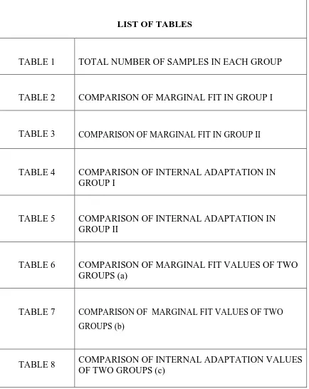
LIST OF TABLES
TABLE 1 TOTAL NUMBER OF SAMPLES IN EACH GROUP
TABLE 2 COMPARISON OF MARGINAL FIT IN GROUP I
TABLE 3 COMPARISON OF MARGINAL FIT IN GROUP II
TABLE 4 COMPARISON OF INTERNAL ADAPTATION IN GROUP I
TABLE 5 COMPARISON OF INTERNAL ADAPTATION IN GROUP II
TABLE 6 COMPARISON OF MARGINAL FIT VALUES OF TWO GROUPS (a)
TABLE 7 COMPARISON OF MARGINAL FIT VALUES OF TWO GROUPS (b)
TABLE 9 COMPARISON OF INTERNAL ADAPTATION VALUES OF TWO GROUPS (d)
TABLE 10 COMPARISON OF INTERNAL ADAPTATION VALUES OF TWO GROUPS (e)
TABLE 11 COMPARISON OF INTERNAL ADAPTATION VALUES OF TWO GROUPS (f)
TABLE 12 COMPARISON OF INTERNAL ADAPTATION VALUES OF TWO GROUPS (f)
LIST OF GRAPHIC DIAGRAMS
GRAPH NO:1 COMPARISON OF MARGINAL GAP BETWEEN ZIRCONIA AND PEEK COPINGS (a)
GRAPH NO:2 COMPARISON OF MARGINAL GAP BETWEEN ZIRCONIA AND PEEK COPINGS (b)
GRAPH NO:3 COMPARISON OF INTERNAL ADAPTATION BETWEEN ZIRCONIA AND PEEK CCOPINGS
(c)
GRAPH NO:4 COMPARISON OF INTERNAL ADAPTATION BETWEEN ZIRCONIA AND PEEK COPINGS
(d)
GRAPH NO:5 COMPARISON OF INTERNAL ADAPTATION BETWEEN ZIRCONIA AND PEEK COPINGS
(e)
GRAPH NO:6 COMPARISON OF INTERNAL ADAPTATION BETWEEN ZIRCONIA AND PEEK COPINGS
(f)
GRAPH NO:7 COMPARISON OF INTERNAL ADAPTATION BETWEEN ZIRCONIA AND PEEK COPINGS
(g)
Abstract
1
INTRODUCTION:
Rapid evolution of CAD/CAM technology (Computer Aided Design, Computer
Aided Manufacture) shows dramatic impact on all disciplines of dentistry especially in
the fields of prosthodontics. There has been a concomitant increase in demand over the
past 25 years. The integration of these technological systems with advances in
biomaterials, can be applied to fabricate inlays, onlays, veneers, crowns, fixed partial
dentures, implant abutments and even full-mouth reconstruction. Recently, several aspects of CAD/CAM systems have had significant technological improvements, these
include the development and application of newer materials in the field of dentistry
Among those materials Polyetheretherketone (PEEK) and zirconia shows
excellent resistance to chemical , thermal , post-irradiation degradation low solubility
and water absorption due to its structure ,when it is compared with other currently
available esthetic computer-aided-design/computer-aided-manufacturing (CAD/CAM)
polymers. The weakest link in the fixed partial denture treatment is the tooth-restorative
margin interface. The longterm success of any fixed partial denture is the good marginal
and internal fit. Improper fit may cause dissolution of cement, percolation of fluid
leading to secondary caries. The advancement of CAD CAM technology (Computer
Aided Design, Computer Aided Manufacture) using optical scanning and computerized
processing produces an excellent fit and adaptation.
Here, the purpose of the present study is to evaluate the marginal fit and internal
Abstract
2 AIMS AND OBJECTIVES:
1. Determine the Marginal fit and Internal adaptaion of copings fabricated
with polyetheretherketone (PEEK)
2. Determine the Marginal fit and Internal adaptaion of copings fabricated with
Zirconia
3. Comparison of Marginal fit and Internaladaptaion of.
copings fabricated with Polyetheretherketone (PEEK) luted with resin
cements
copings fabricated with Zirconia luted with resin cements.
METHODOLOGY:
In the present study,an in vitro study was planned to check both the marginal fit and
internal adaptation in acrylic models for that maxillary first premolar was prepared. The
selected tooth was prepared for all ceramic crowns with ideal dimension. The
preparation depths were 1mm axially and 2mm occlusally. The shoulder finish line
margins were supra-gingival and the tooth preparation had a convergence angle of six
degrees.
Using addition silicone putty (AQUASIL), an impression of prepared
maxillary first premolar was made and wax tooth model was fabricated from the
impression. The wax tooth model was invested and casted to fabricate cobalt –
Abstract
3
The cobalt – chromium tooth model is duplicated using additional silicone to
fabricate 30 heat cure acrylic models. The samples were divided into two groups. Each
group consist of fifteen copings (15 PEEK & 15 Zirconia).
A self cure resin luting agent was used to cement the
Polyetheretherketone (PEEK) & Zirconia copings to each model. An equal length of
the luting resin is dispensed on the mixing pad, was done according to the manufacturer
instructions, the mixed cement was painted on the internal surfaces of the copings.
Copings were luted on the prepared tooth model with finger pressure for
10 minutes and the excess cements from the margins are removed. Sagittal cross section
of the sample has been made using a Diamond wheel disc, having a disc thickness of
0.01mm cutting at high speed using a Tooth cutting lathe for all the 30 samples . To
prevent heat production entire sectioning procedure was carried out with continuous
irrigation from the three way syringe .Values were recorded under a Field Emission
Scanning electron microscope 1000X magnification .
RESULTS
In the present study marginal fit and internal adaptation measured as values, among those two groups Polyetheretherketone (PEEK) copings group materials showed
the lowest mean value of (30.3±5.1) for marginal gap, (29.1±5.8) for internal gap
whereas zirconia copings group showed a mean value of (50.26±16.02) and
(32.8±5.2)respectively. These results were statistically analyzed using ANOVA (Post
Abstract
4 SUMMARY AND CONCLUSION
Although it was proved that excellent marginal fit and internal adaptaion
compared with zirconia coping. However, the numerical values presented for the
marginal and internal adaptation of polyetheretherketone (PEEK) and zirconia coping
are both clinically acceptable. Marginal fit and internal adaptation important factors in
increasing the longevity of the restoration. The future research on Field Emission
Introduction
5
Computer-aided design and computer-aided manufacturing
(CAD/CAM systems) represent the pinnacle of computer technology with lots of
potential applications in the fields of dentistry. CAD / CAM systems in dentistry
consists basically of three components .The first component is a device that reflects
the preparation of teeth and other supporting tissues and is responsible for spatial data
digitalization • The second component consists of computer which plans and calculate
body form of restoration. The third component represents a numerically controlled
milling machine which from the basic shape produces dental restoration.
Computer-aided design and computer-aided manufacturing (CAD/CAM)
technologies aim for a standardized and accurate production of dental restorations out
of high strength materials such as ceramic, zirconia, composite, and acrylic resins. The
main concern of any dental restoration is give an accurate fit and it supposed to
withstand the functional forces1,2.
Traditional cast restorations are handmade whereas CAD/CAM technologies
uses a software which designs a dental restorations which gives an accurate fit and are
capable of replacing the existing casting method3,4. Among such CAD/CAM
Introduction
6
toughness, excellent strength and esthetic properties, due to which they are preferred
for restorations.
Zirconium crowns or copings are made up of zirconium oxide or zirconia.
Zirconia is a white powdered metal which has the ability to be radiopaque in the X-rays
which makes them stand ahead from the regular and traditional materials. There is no
anaesthetic grey line visibility compared to that of conventional metal-based ceramic
restorations.
Most of the dental restorations undergo corrosion with the years of regular use by
the patients. Various fluids and foods consumed over years lead such corrosion of the
dental restorations. However zirconia shows corrosion resistance which contribute
majorly to having a long life.Zirconia provides restorations which were quickly
produced, durable and with good aesthetics. With its strength and easy milling
properties, zirconia is a great option for a variety of clinical situations, especially for
posteriors and long-span restorations.
Polyetheretherketone (PEEK) is a synthetic, tooth colored polymeric material
that has been used as a biomaterial for many years . It has white color and excellent
mechanical properties, hence it has been proposed for other prosthodontic
Introduction
7
applications such as fixed prostheses and removable prostheses.The monomer unit of
polyetheretherketone monomer polymerizes via step-growth dialkylation reaction of
bis-phenolates to form polyetheretherketone8.A variety of procedures have been
suggested to condition the surface of PEEK in order to facilitate its bonding with resin
composite crowns8.
Even though air abrasion with and without silica coating creates a more
wettable surface , etching with sulphuric acid creates a rough and chemically altered
surface which enables it to bond more effectively with hydrophobic resin composites8.
No significant differences were observed in the tensile bond strength of PEEK crowns
and dentin abutments using air abrasion and sulfuring acid etching techniques 8,9 .
Many studies suggest that PEEK can be used under resin composite as a coping
material. Because the mechanical properties of PEEK are similar to those of dentin
and enamel, PEEK could have an advantage over alloy and ceramic restorations9.
CAD-CAM designed composites and polymethylmethacrylate (PMMA) fixed
dentures have superior mechanical properties compared to conventional fixed dentures
.PEEK is another material that can be used as an alternative to PMMA for CAD-CAM
restorations9,10. Three-unit PEEK fixed partial denture, manufactured via CAD-CAM
Introduction
8
has been suggested to have a higher fracture resistance than pressed granular- or
pelletshaped PEEK dentures11 .
The fracture resistance of the CADCAM milled PEEK fixed dentures is much
higher than those of lithium disilicate glass-ceramic (950N), alumina (851N) and
zirconia (981-1331N) 12. The abrasive properties of PEEK are excellent . Despite of
significantly low elastic modulus and hardness, abrasive resistance of PEEK is
competitive with metallic alloys12.Meanwhile, polyetheretherketone (PEEK), which is
chemically stable and highly durable in mechanical conditions such as tension, fatigue,
and bending13.
Recently Bioactive PEEK nano-composites are also available. In this type of
bioactive inorganic particles have been incorporated to PEEK using melt-blending and
compression molding techniquesr inorder to increase the bioactivity.14 However,
incorporating bioactive HAp particles in the size range of 2–4 mm has a negative
impact on the mechanical properties of PEEK . This can be overcome using nano-sized
particles instead of larger particles 15,16. Implants made of PEEK nano-composites
have a number of advantages such as increased bioactivity better mechanical
Introduction
9
Today the CAD/CAM techniques dominated the old technologies for
manufacturing crown and bridges. The CAD/CAM techniques used in dentistry for the
production which include both the subtractive and additive manufacturing (AM) such
as rapid prototyping improved the quality and fit of these restorations while compared
to old fabrication methods. Currently available CAD/CAM materials offer excellent
strength and esthetics now offers automated production, accuracy, esthetically
pleasing and strong restorations, and flexibility to both the dentist and the laboratory
technician.
For any dental restoration there should be proper marginal fit and internal
adaptation. When the marginal fit and internal adaptation is poor, plaque deposition,
periodontal destruction, relapse of dental caries, and, ultimately, the failure of the
restoration can ensue; therefore, the fit of the dental restoration plays a pivotal role in
the long-term success of the prostheses19.
If the dentist claims to be a leader in the development of inlays, onlays, crowns
and bridges, it is necessary to practice the application of CAD / CAM technology in
aesthetic fixed restorations. The use of this technology provides a high quality,
Introduction
10
The purpose of this study is to evaluate and compare the marginal fit and
internal adaptation of copings fabricated with PEEK (Polyetheretherketone) and
Aims and Objectives
11
AIMS
To determine and compare the Marginal fit and Internal adaptation of copings
fabricated with Polyetheretherketone (PEEK) and Zirconia luted with resin
cements.
OBJECTIVES
To determine the Marginal fit and Internal adaptaion of copings fabricated with polyetheretherketone (PEEK)
To determine the Marginal fit and Internal adaptaion of copings fabricated with Zirconia
To compare the Marginal fit and Internal adaptation
i. PEEK copings and
Review of literature
12
Computer-aided design and computer-aided manufacturing
(CAD/CAM) technology introduced in the dentistry by the year 1985. The
development of this advanced technology went from the machine copy milling through
to fully computer controlled system for the production of crowns and bridges. There
are numerous advantages to facilitate the work of the dentist, but also users of dental
services that are becoming more demanding in terms of aesthetics by providing the
restoration with accurate fit. This innovative technologies, have a greater role in
prosthodontics in terms of dental pratice and also in dental technical laboratories.
Improper marginal fit and adaptation which leads to cement solubility
and plaque retention which is potentially detrimental to both tooth and periodontal
tissues. Minimal marginal gaps results in less gingival irritation, cement dissolution,
recurrent carries and marginal discoloration. Computer-aided design and
computer-aided manufacturing (CAD/CAM) technology generated prosthesis provides the
restoration with accurate fit and adapation when compared with traditional methods.
Advantages of using Computer-aided design and computer-aided
manufacturing CAD / CAM technology for dentists are:
•Patient comfortability and satisfication
• Significantly reduced costs .
• Reduced consumption of materials & Increased productivity
Review of literature
13
This literarure review had shown comparision of marginal and internal fit of various
fabrication methods
Sulaiman F et al (1997)1 evaluated and compared marginal fit of three all-ceramic crown systems (In-Ceram, Procera, and IPS Empress) and concluded
that there was an no significant change in the core fabrication, porcelain
veneering, and glazing and that larger marginal discrepancies were seen in the
facial and lingual margins than the mesial and distal margins.
Groten M et al (1997)2 evaluated the marginal fit of copy-milled Celay In-Ceram crowns after different fabrication steps and compared
light-microscopic with scanning-electron-light-microscopic data and stated that there was
no alteration in the marginal gap width during manufacturing steps after copy
milling and concluded that clinically excellent marginal fit was seen in the Celay
In-Ceram method.
Konstantoulakis E et al (1998)3investigated the the marginal fit and surface roughness of full coverage crowns made with a conventional and an
accelerated casting technique and concluded that conventional investing and
casting techniques were time-consuming but accelerated casting techniques have
Review of literature
14
Oruc S et al (2000)4 assessed the marginal and inner fit of metal-ceramic restorations and frameworks made with a nickel-chromium alloy (Remanium
CS) and a commercially pure titanium (Rematitan) and the fit of crowns
compared with SEM before and after firing of ceramic material zirconia and
revealed that the fit of the base metal alloy metal-ceramic crowns was better
than the commercially pure titanium metal-ceramic crowns.
Luthardt R G et al (2002)5 evaluated the strength and reliability as well as the surface roughness of Y-TZP(yttria –stabilized tetragonal zirconia
polycrystals) zirconia ceramic machined under conditions stimulating the inner
surface grinding of crown and FPD depending on the grinding parameter and
concluded that strength and surface roughness parameters are dependent on each
other.
Cho L et al (2002)6 evaluated the effect of variations in tooth preparation design on the marginal accuracy before and after cementation and on the fracture
strength of the ceromer/fiber reinforced composite crown and concluded that
decreasing the axial convergence angle of the ceromer/fiber-reinforced
composite crowns diminished their marginal gap and increased their fracture
Review of literature
15
Behr M et al (2003)7 investigated the marginal adaptation and fracture resistance of heat-pressed glass-ceramic and fiber-reinforced composite molar
crowns luted with resin, resin-modified glass-ionomer, or zinc-oxide-eugenol-
free cements and concluded that the highest fracture resistance and marginal
adaptation were found for all-ceramic and glass fiber-reinforced composite
molar crowns if they were luted with resin cement.
Quintas A F et al (2004)8 evaluated the effect of different finish lines, ceramic manufacturing techniques and luting agents on the vertical discrepancy
of ceramic copings and concluded that the ceramic manufacturing technique
appeared to be the most important factor tested for the definitive vertical
discrepancy of all ceramic copings, with lower mean values for procera copings.
Albert F E et al (2004)9 investigated the microleakage and marginal adaptation of Procera AllCeram crowns were cementated with zinc phosphate,
glass-ionomer, resin-modified glass ionomer, or resin cement and concluded that
crowns luted with zinc phosphate cements resulted in the highest percentage of
extensive microleakage.
Jesus Suarez M et al (2005)10evaluated the compare the marginal fit of two kinds of metal-ceramic crowns from commercially pure titanium and
Review of literature
16 Procera titanium crowns and concluded that compared with two groups casting
titanium results with very good marginal fit.
Kunii J et al (2007)11 investigated the effect of post-machining sintering on marginal and internal fit of CAD/CAM-fabricated zirconia frameworks and
concluded that fit of the single crown coping was excellent . Marginal and
internal fit of three unit and four unit frameworks were within clinical
acceptance.
Manicone P F et al (2007)12 summarised the various properties and clinical application concluded that good success rate for zirconia FPDs and
implant abutments . Zirconia can also be used to improve the aesthetic outcome
of implant-supported rehabilitations because it has very good biological and
mechanical properties.
Al Wazzan KA et al (2007)13 investigated the marginal accuracy and internal fit of complete cast crowns and three-unit fixed partial denture with
commercially pure titanium and Titanium-Aluminum-Vanadium alloy
concluded that the Titanium-Aluminum-Vanadium alloy demonstrated a better
fit than commercially pure titanium.
Review of literature
17 partial dentures (FPDs) fabricated using three different computer aided
design/computer aided manufacturing (CAD/CAM) all-ceramic systems before
and after porcelain firing cycles and after glaze cycles and concluded that the
three zirconium-oxide-based ceramic CAD/CAM systems demonstrated a
comparable and acceptable marginal fit. Everest and Procera group showed
marginal gap compared to the Lava system.
Quante K et al (2008)15 evaluated the marginal and internal fit of metal-ceramic crowns fabricated with a new laser melting procedure and the influence
of ceramic firing on the marginal and internal accuracy of these crowns and
concluded that the laser melting technology exhibited an excellent marginal and
internal accuracy that is comparable to conventional procedures.
Beuer F et al (2008)16 summarized CAD/CAM-technologies and systems available for dentistry and concluded that CAD/CAM generated dental
restorations which included new, almost defect-free, industrially prefabricated
and controlled materials, which had better quality and reproducibility.
Marchack B W et al (2008)17 evaluated the customization of milled zirconia copings to provide even and controlled porcelain thickness with the aim
of decreasing cohesive porcelain fracture and other failures and concluded that
Review of literature
18
adequate even porcelain thickness, and butt joints at the porcelain-to-coping
junction.
Koutayas S O et al (2009)18 reviewed various zirconia manufacturing techniques and their potential for successful clinical application in dentistry
and concluded that all-ceramic restoration has a various good physical and
mechanical properties along with its good strength, fit, esthetics and
biocompatible , which makes it widely used in the field of dentistry.
Vagkopoulou T et al (2009)19 studied the evolution and development of zirconia as a biomaterial and concluded that advanced specifications are
required to ensure the long- term stability and success of Y-TZP bio-medical
components and introduction of new modification with enhanced properties
can be used in various applications.
Roediger M et al (2010)20 studied the performance of three- and four-unit fixed partial dentures (FPDs) with frameworks fabricated of yttria partially
stabilized zirconia and concluded that within a mean observation period of 4
years, sufficient survival rates were reported for zirconia-based posterior fixed
Review of literature
19
Baig M R,et al (2010)21 evaluated the marginal fit with respect to gap and overhang of Y-TZP (yttria-stabilized tetragonal zirconia polycrystals)
ceramic crowns and compared them with lithium disilicate pressable and
complete metal crowns and concluded that Cercon system showed significantly
larger marginal gaps than both the IPS Empress II and complete metal crowns.
Grenade C et al (2011)22 investigated the internal and marginal fit of single tooth zirconia copings manufactured with a CAD/CAM process (Procera;
Nobel Biocare) and concluded that marginal fit of Procera copings showed
comparatively better marginal fit than Ceramill copings.
Korkut L et al ( 2011)23 compared the marginal and internal fit and also the microleakage of zirconia infrastructures (Procera All-Zircon, Cercon Smart
Ceramics) in contrast to heat-pressed ones (Empress ) and concluded that there
was statistically significant differences were observed between marginal and
internal fitting accuracy but there was no significant differences in microleakage.
Karatasli O et al (2011)24 analysed marginal adaptations of different copings fabricated with CAD/CAM or MAD/CAM and concluded that a the
utilization of hard coping material increases the fracture resistance of
Review of literature
20 which may increase marginal gap, creating poorly adapted restorations
clinically.
Moldovan O et al (2011)25 evaluated the effect of the microstructure on the Weibull and slow crack growth (SCG) parameters on the lifetime of three
ceramics used as framework materials for fixed partial dentures (FPDs)and
summarized that YZ (YZ – Vita In-Ceram YZ ) showed the best mechanical
performance.
Martins LM et al (2012)26 investigated the internal fit (IF) of
glass-infiltrated alumina , yttria-stabilized tetragonal zirconia polycrystals and metal-
ceramic crowns and stated that metal-ceramic group demonstrated
significantly lower values than the all-ceramic groups.
Stawarczyk B et al (2013)27 evaluated the surface properties of polyetheretherketone (PEEK) and its bond strength with two veneering resins
after different conditioning methods and concluded that silica-coated PEEK
surfaces showed the highest wettability ,roughness, shear bond strength values
after acid etching with sulfuric acid.
Review of literature
21 bioactivity of three-dimensional porous and nanostructured network on
polyetheretherketone(PEEK) concluded that three dimensional porous and
nanostructured network on PEEK were produced by sulfonation and subsequent
water immersion technique.
Gwinner F P et al (2013)29 evaluated the vertical marginal gap of sintered gold copings and metal-ceramic crowns with different finish line
preparations (beveled round shoulder (BRS) and a beveled long chamfer (BLC)
and concluded that marginal gap is influenced by ceramic application on
copings fabricated on BLC preparation, and greater marginal gaps were found
for restorations with BRS finish line.
Li R W K et al (2014)30 evaluated ceramics are widely used as indirect restorative materials in dentistry because of their high biocompatibility and
pleasing aesthetics concluded that ceramics have met with variable clinical
success, multiple options are now available to the clinicians for the fabrication
of aesthetic all ceramic restorations.
Re D et al (2014)31investigated the marginal fit of Lava Zirconia crown-copings on chamfer and shoulder preparations and concluded that the marginal discrepancies 120 μm was clinically acceptable and that no difference of
Review of literature
22 marginal gap seen in the Chamfer and shoulder preparations .
Stawarczyk B et al (2014)32 analysed the effect of chemical treatments of PEEK on tensile bond strength (TBS) to veneering resins with special
emphasis on surface free energy (SFE) and surface roughness (SR) and
concluded that sufficient TBS for bonding to veneering resin can only be
achieved when additional adhesive materials were applied.
An s et al (2014)33 analysed the the marginal fit of zirconia copings designed with an iTero digital scanner and conventional impression technique
and concluded that the marginal gap between the restoration and definitive cast
base metal die was greater in the digital impression method than the
conventional impression method
Jalalian E et al (2015)34 evaluated the effect of porcelain firing cycle and different thicknesses of IPS e.max core on marginal accuracy of all-ceramic
restorations and concluded that by doing this it can increase marginal gap in IPS
e.max CAD restorations .
Rajan B N et al (2015)35 evaluated the marginal fit and internal adaptation of zirconia copings fabricated by two CAD - CAM systems and
Review of literature
23 concluded that CEREC -In Lab MC XL showed better internal adaptation and
marginal fit than CERAMILL.
Jalali H et al (2015)36 compared the marginal adaptation and fracture resistance of a zirconia-based all-ceramic restoration with two preparation
designs and concluded that less aggressive preparation of proximal and lingual
finish lines for the preservation of tooth structure in all-ceramic restorations
does not adversely affect the marginal adaptation or fracture strength of the final
restoration.
Najeeb S et al (2015)37 evaluated applications of polyetheretherketone (PEEK) in oral implantology and prosthodontics and concluded that PEEK is
used in various field of dentistry and also as dental implants due to its similar
physical and mechanical properties to bone and dentin.
Stawarczyk B et al (2015)38 analyzed the influence of different fabrication methods of three-unit reinforced polyetheretherketone composite
(PEEK/C) fixed dental prostheses (FDPs) on fracture load and concluded that
CAD/CAM milled FDPs and those pressed from PEEK/C-pellets showed
spontaneous and brittle fractures near the pontic without deformation of the FDP
Review of literature
24
Stock V et al (2016)39 evaluated the retention force between polyetheretherketone , cobalt-chromium , zirconia and galvanic secondary
crowns and concluded that PEEK has satisfactory higher retention force when
compared with cobalt-chromium, zirconia and galvanic secondary crowns .
Bae S Y et al (2016)40 analyzed three dimensional marginal and internal fit of copings fabricated with polyetherketoneketone (PEKK) and zirconia and
concluded that PEKK copings has an excellent marginal and internal fit when
compared with zirconia copings.
Rocha R F V et al (2016)41 analyzed effect of different surface treatments on the bond strength of PEEK bonded to human dentin and concluded that both
Sandblasting and sulphuric acid treatment were effective in promoting similar
bonding among PEEK, resin cement and dentin.
Sinha N et al (2017)42 evaluated the versatility of PEEK as a dental material for FPD framework and concluded that utilizing PEEK as a framework
for FPD yielded very satisfactory results with high degree of patient comfort and
acceptability due to its light weight nature and long-lasting effect on the
Review of literature
25
Park J Y et al (2017)43 evaluated the marginal and internal gaps of dental prosthesis fabricated from the conventional technique, silicone replica technique
(SRT) and three-dimensional superimposition analysis and concluded that these
three fabrication methods exhibited marginal gaps which were clinically
acceptable .
Skirbutis G et al (2017)44 reviewed polyether ether ketone (PEEK) and its characteristic use in prosthodontics and concluded that PEEK polymer is
suitable for use in the field of prosthodontics due to its good mechanical,
chemical, physical properties .
Habib S R et al (2017) 45 investigated the effect of shoulder versus chamfer margin design on the marginal adaptation of zirconia (Zr) copings and
concluded, that the chamfer margin design appeared to offer the same adaptation
results as the shoulder margin design.
Alhavaz A H et al (2017)46 evaluated and aimed to compared the fracture load of restorations fabricated with two different zirconia core designs and
concluded that that customized core design significantly increased the fracture
resistance of all-ceramic posterior crowns compared with the conventional
Review of literature
26 design, and the obtained crowns fractured at a significantly higher load.
Kalavathi M et al (2017) 47 compared the marginal Accuracy of Castings fabricated with ringless casting investment system and metal ring casting
investment system and concluded that ringless casting technique had produced
better marginal accuracy compared with conventional casting technique.
Riccitiello F et al (2018)48 evaluated the marginal and internal adaptation of zirconia and lithium disilicate single crowns, and concluded that CAD-CAM
processing techniques for both zirconia and lithium disilicate produced accurate
marginal gaps than the heat-pressing procedures.
Arora Aet al (2018)49 evaluated the marginal and internal adaptation of cobalt-chromium copings fabricated from conventional wax pattern,
three-dimensional (3D)-printed resin pattern, and laser sintering technique and
concluded that excellent marginal fit was observed in DMLS and coping
fabricated with conventional technique showed best internal fit.
James A E et al (2018)50 evaluated the amount of marginal discrepancy produced by Co-Cr copings made by various fabrication methods which included
Review of literature
27 and ringless casting and concluded that even though the marginal gap was found
to vary with the fabrication method, all measurements of marginal gap of all
Materials and Methodology
28 In the present study an effort was made to find out the Marginal fit and Internal
adaptation of Polyetheretherketone (PEEK) and Zirconia copings luted with resin
cement of the two groups.
MATERIALS:
1) Natural maxillary 1st premolar.
2) Tooth preparation burs (SHOFU CROWN & BRIDGE PREPARATION KIT,
JAPAN).
3) Addition silicone putty impression material (AQUASIL, GERMANY).
4) Dental wax (HINDHUSTAN, INDIA).
5) Cobalt – Chromium Pellet.
6) Heat cure acrylic material (DPI, INDIA).
7) Self – adhesive resin luting cement (RELY X U 200, GERMANY).
8) PEEK copings (DENTCARE, INDIA -15 no.s)
9) Zirconia copings (DENTCARE, INDIA -15 no.s)
10) Diamond wheel disc (EDENTA, SWISS)
11) Investment material. (PHOSPHATE BONDED INVESTMENT- S.P.E
Materials and Methodology
29
EQUIPMENTS:
1) Airotor hand piece (NSK, JAPAN).
2) Casting machine (BEGO FORNAX MODEL 26300, GERMANY).
3) Milling unit (LAVA CNC500, GERMANY).
4) Tooth cutting lathe (RAY FOSTER, USA).
5) Field Emission Scanning electron microscope.(ZEISS SUPRA 55)
6) Stereomicroscope ( LEICA M125C)
SAMPLING:
Sample size of each group→ 15
a. Total sample size of the study: 30
Scientific basis of sample size used in the study:
n= Z2S2
d2
n = sample size
Materials and Methodology
30
S = Std. deviation of marginal fit = 1.5 ( so xean)
d = Absolute precision = 1.2
n = 6
So in 1 group = 6
2 group = 12
In my study, sample size will be 30.
SAMPLES:
In the present study, 30 copings were used as samples (15 Polyetheretherketone
(PEEK) copings , 15 Zirconia copings ) total of 30 copings were divided into 2 groups.
Group I, consists of 15 PEEK copings
Group II consists of 15 Zirconia copings
METHODOLOGY:
Materials and Methodology
31 1. Sample selection.
2. Sample preparation.
3. Sample grouping and copings fabrication.
4. Copings luting and curing.
5. Sample sectioning.
6. Measurements.
SAMPLE SELECTION:
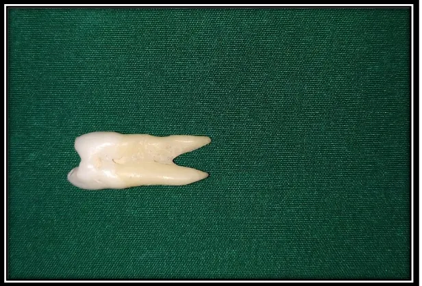
In the present study freshly extracted human maxillary first premolars were
selected (orthodontic purposes). The crown size of 8 mm (mesio-distally) were
selected which are free from carious, restoration and no apparent defects.
SAMPLES PREPARATION:
The selected tooth was prepared for all ceramic crowns with ideal
dimension. The preparation depths were 1mm axially and 2mm occlusally. The
shoulder finish line margins were supra-gingival and the tooth preparation had a
Materials and Methodology
32
impression of prepared maxillary first premolar was made and wax tooth model was
fabricated from the impression.
The wax tooth model was invested and casted to fabricate cobalt – chromium
metal tooth model. The cobalt – chromium tooth model is duplicated using additional
silicone to fabricate 30 heat cure acrylic models
SAMPLES GROUPING AND COPINGS FABRICATION
The samples were divided into two groups. Each group consist of fifteen copings
(15 Polyetheretherketone (PEEK) copings & 15 Zirconia copings)
Group 1: Polyetheretherketone ( PEEK )copings
Group 2: Zirconia copings
COPINGS LUTING AND CURING ;
A dual cure resin luting agent (Rely X U200 Self-Adhesive resin,3M, Germany)
was used to cement the copings to each model, an equal length of the luting resin is
dispensed on the mixing pad, was done according to the manufacturer instructions, the
Materials and Methodology
33
Copings were luted on the prepared tooth model with finger pressure for 10 minutes
and the excess cements from the margins are removed.
SAMPLE SECTIONING:
Sagittal cross section of the sample has been made using a Diamond wheel
disc, having a disc of thickness 0.01mm cutting at high speed using a Tooth cutting
lathe (RAY FOSTER, USA) for all the 30 samples.( entire procedure was carried out
with continuous irrigation from the three way syringe to reduce heat production).
MEASUREMENT:
Marginal fit:
The sectioned samples were scanned under field emission scanning electron
microscope and stereomicroscope for marginal fit. The distance between the most
extended point of the coping margin and the external marginal line of the prepared tooth
was used to evaluate the marginal gap. For this, two measurement points were
Materials and Methodology
34
Internal Adaptation:
The sectioned samples were scanned under field emission scanning electron
microscope and stereomicroscope for Internal adaptation. For evaluating internal
adaptation, the perpendicular distances from the internal surface of the coping to the
external surface of the preparation were measured. For this, five measurement points
were determined, i.e., c and g (1 mm away from the margin), d and f (maximum
convexity on the cusp tip), and e (maximum concavity in the central fossa).
Measurement positions for - marginal fit (a and b)
- marginal fit (a and b) assessing
Materials and Methodology
35
STATISTICAL ANALYSIS:
The result data were statistically analyzed. Analysis was carried out with one
way analysis of variance (ANOVA) followed by Post Hoc and Dunnet ‘t’ test to find
Figures
FIG 1: NATURAL 1st PREMOLAR
[image:68.612.227.443.446.698.2]
FIG 2: PREPARED NATURAL 1st PREMOLAR (OCCULUSAL VIEW)
Figures
FIG 3: WAX PREPARATION- PATTERNED FOR MASTER DIE
[image:69.612.173.480.474.706.2]
Figures
FIG 5: CASTING RING
Figures
FIG 7: HEAT CURE ACRYLIC TOOTH MODELS (30 No’s)
Figures
FIG 10: SELF ADHESIVE RESIN LUTING CEMENT
FIG 11:LUTED ZIRCONIA COPINGS & FIG 12:PEEK COPINGS
Figures
Fig 13: DIAMOND WHEEL BURS
Figures
Fig 15: SECTIONED SAMPLES
Figures
Fig 17: FIELD EMISSION SCANNING ELECTRON MICROSCOPE (SUPRA 55)
Figures
[image:76.612.181.498.437.661.2]Fig 19: SPUTTERING WITH GOLD & PALLAIDIUM
Figures
[image:77.612.169.511.428.714.2]Fig 21: CARBON TAPE
Figures
[image:78.612.166.512.430.678.2]Fig 23: BEFORE PLACING SAMPLES – COMPUTER MONITOR
Figures
[image:79.612.171.508.484.709.2]Fig 25: INNER VIEW- FIELD SCANNING ELECTRON MICROSCOPE
Figures
[image:80.612.184.494.467.695.2]Fig27: SAMPLES PLACED
Figures
Fig 29: STEREO MICROSCOPE( LEICA M125C)
Figures
Fig31: AIROTOR
FFI
FIG 32: CASTING MACHINE FIG 33: CAD CAM – MILLING MACHINE
Results and Observations
36
Statistical analysis:
The data was analyzed by Statistical Package for Social Sciences (SPSS
16.0) version. One way ANOVA (Posthoc) followed by Dunnet ‘t’ test applied
to find the statistical significant between the groups. P value less than 0.05
considered statically significant at 95% confidence interval.
Table I
: Total number of samples in each group.Table II
:
Comparison of marginal fit in group I. – (a &b)Table III:
Comparison of marginal fit in group II. – (a &b)Table IV
: Comparison of internal adaptation in group I. – (c,d,e,f,g)Table V:
Comparison of internal adaptation in group II. – (c,d,e,f,g)Table VI:
Comparison of Marginal Fit values of Two groups (a)Table VII:
Comparison of Marginal Fit values of Two groups (b)Table-VIII:
Comparison of Internal adaptation values of Two groups ( c) Measurement positions for internal adaptation (c) axial, (d) buccal cusp, (e) fossa, (f) lingual cusp, (g) axialMeasurement positions for - marginal fit (a and b)
Results and Observations
37
Table-IX:
Comparison of Internal adaptation values of Two groups (d)Table-X:
Comparison of Internal adaptation values of Two groups (e)Table-XI:
Comparison of Internal adaptation values of Two groups (f)
Tables
38
TABLE I:
TOTAL NUMBER OF SAMPLES IN EACH GROUP
GROUP I 15 PEEK COPINGS
GROUP II 15 ZIRCONIA COPINGS
TABLE II:
COMPARISON OF MARGINAL FIT IN GROUP I
S. No
a b
1 20.5 21.3
2 21.2 40.2
3 23.2 26.9
4 30.1 26.7
5 30.7 34.2
6 29.5 32.3
7 28.5 30.7
8 28.9 29.3
9 31.2 22.4
10 27.5 24.6
11 28.9 26.5
12 30.2 24.6
13 33.7 23.2
Tables
39
14 32.6 26.8
15 28.4 31.2
TABLE III:
COMPARISON OF MARGINAL FIT IN GROUP II
S. No
a b
1 53.9 34.5
2 64.2 25.8
3 65.2 29.5
4 89.2 33.2
5 52.6 39.2
6 66.2 42.3
7 59.8 36.8
8 61.2 34.5
9 48.2 44.2
10 59.2 32.8
11 60.2 34.8
12 52.3 36.8
13 49.3 28.2
14 56.8 34.8
15 58.4 38.8
Tables
40
TABLE IV
:COMPARISON OF INTERNAL ADAPTATION IN GROUP I
S. No
c d e f g
1 20.5 22.1 20.6 22.3 29.8
2 21.2 40.2 24.6 38.5 36.5
3 23.2 26.9 19.8 28.4 28.8
4 30.1 26.7 20.2 34.1 30.1
5 30.7 34.2 33.1 29.3 28.4
6 29.5 32.3 29.3 21.9 22.4
7 28.5 30.2 39.2 20.2 27.6
8 28.9 29.3 14.7 27.6 28.9
9 27.6 34.6 28.6 21.6 32.4
10 30.2 31.2 26.7 26.8 34.2
11 26.8 28.6 34.2 24.6 36.2
12 28.6 25.8 32.4 28.4 28.2
13 32.2 28.6 28.2 29.6 28.6
14 30.6 39.7 14.8 24.2 28.4
15 24.6 32.2 18.6 28.6 35.3
Tables
41
TABLE V:
COMPARISON OF INTERNAL ADAPTATION IN GROUP II
S. No
c d e f g
1 60.1 49.5 29.7 31.7 61.3
2 61.1 64.2 28.3 29.2 53.9
3 58.9 62.1 30.3 23.5 44.2
4 55.1 62.4 19.7 28.9 41.1
5 54.1 23.4 23.4 32.1 63.2
6 56.8 44.2 32 33.1 56.1
7 60.3 30.8 31.2 30.8 54.1
8 58.8 29.3 30.2 29.2 59.2
9 57.6 32.4 30.3 28.6 60.4
10 56.9 31.2 29.8 38.2 56.9
11 59.7 28.6 26.9 28.6 52.6
12 60.8 30.2 29.8 31.8 59.3
13 58.6 29.8 27.8 32.4 60.3
14 58.9 27.8 26.4 32.2 52.6
15 61.2 29.5 28.6 31.4 62.6
Tables
42
TABLE-VI:
COMPARISON OF MARGINAL FIT VALUES OF TWO GROUPS (a)
Groups N
MARGINAL FIT(µm)
Mean± Std.Deviation
P value
Group-I 15 26.733 ±4.0176 0.001
Group-II 15 64.473±11.2136 0.001
T-Test p < 0.001 sig
TABLE-VII:
COMPARISON OF MARGINAL FIT VALUES OF TWO GROUPS (b)
Groups N MARGINAL FIT(µm)
Mean± Std.Deviation
P value
Group-I 15 30.387±5.1726 0.001
Group-II 15 32.853±5.2345 0.001
T-Test p > 0.05 Not sig
TABLE-VIII:
COMPARISON OF INTERNAL ADAPTATION VALUES OF TWO GROUPS (c)
Groups N INTERNAL ADAPTATION(µm)
Mean± Std.Deviation
P value
Group-I 15 24.580±6.7824 0.001
Group-II 15 58.387±2.6262 0.001
Tables
43
TABLE-IX:
COMPARISON OF INTERNAL ADAPTATION VALUES OF TWO GROUPS (d)
Groups N INTERNAL ADAPTATION(µm)
Mean ± Std.Deviation
P value
Group-I 15 29.120±5.8732 0.001
Group-II 15 50.267±16.0283 0.001
T-Test p < 0.001 sig
TABLE-X:
COMPARISON OF INTERNAL ADAPTATION VALUES OF TWO GROUPS (e)
Groups N
Mean± Std.Deviation
P value
Group-I 15 29.160±3.8400 0.001
Group-II 15 27.673±4.0700 0.001
T-Test p > 0.05 Not sig
TABLE-XI:
COMPARISON OF INTERNAL ADAPTATION VALUES OF TWO GROUPS (f)
Groups N
Mean± Std.Deviation
P value
Group-I 15 28.207±2.4253 0.001
Group-II 15 29.060±3.2450 0.001
T-Test p > 0.05 Not sig
Tables
44
TABLE-XII:
COMPARISON OF INTERNAL ADAPTATION VALUES OF TWO GROUPS (g)
Groups N
INTERNAL ADAPTATION(µm)
Mean± Std. Deviation
P value
Group-I 15 25.700± 2.6385 0.001
Group-II 15 52.987±8.0321 0.001
Graphs
Graph-1: Comparison of Marginal gap between Zirconia and PEEK
copings (a)
Graphs
Graph-3: Comparison of Internal adaptation between Zirconia and
PEEK copings (c)
Graph-4: Comparison o