R E S E A R C H
Open Access
Augmented decoders for LDPC codes
Alex R. Rigby
1*, JC Olivier
1, Hermanus C. Myburgh
2, Chengshan Xiao
3and Brian P. Salmon
1Abstract
The performance of a belief propagation decoder for low-density parity-check codes is limited by the presence of trapping sets in the code’s graph. This leads to an error floor at higher signal-to-noise ratios. We propose the use of an augmented decoder which operates by iteratively decoding on a set of graphs which have a subset of repeated check nodes. We compare the augmented decoder to other modified belief propagation decoders that have been presented in the literature. We show that for all the codes considered, the augmented decoder yields the best frame error rate in the error floor region.
Keywords: LDPC codes, BP decoding, Trapping sets, Error floor mitigation
1 Introduction
Low-density parity-check (LDPC) codes provide good error correction performance when a belief propagation (BP) decoder is used [1]. BP computes the marginal prob-abilities of the transmitted bits with reasonable accuracy even though the graph representation of the code con-tains loops. These loops can lead to trapping sets which degrade decoder performance, causing an error floor at high signal-to-noise ratios (SNR) [2].
It is possible to design LDPC codes for good per-formance with a BP decoder by optimizing the degree distribution [3]. It is also possible to avoid loops in the construction of the code’s graph through methods such as progressive edge-growth (PEG) [4]. The harmfulness of particular trapping sets to BP performance can be ana-lyzed, and codes can be designed to avoid them [5]. For a given code, it is possible to add additional parity checks at the transmitter [6], but this comes at a potential rate penalty.
Several different modifications to the BP decoder have been suggested in the literature. Generalized LDPC (G-LDPC) decoders are presented in [7], these aim to mitigate the effect of prominent trapping sets by combining associ-ated check nodes into “super nodes.” The non-uniqueness of the code’s parity-check matrix (and hence its graph) is utilized in [8] where BP is employed in parallel on a set of equivalent graphs. Backtracking was proposed in [9], which involves the iterative sign flipping of a BP message
*Correspondence:[email protected]
1College of Sciences and Engineering, University of Tasmania, Hobart, Australia Full list of author information is available at the end of the article
associated with a non-satisfied check node. Limiting the magnitudes of messages passed in BP can also successfully reduce the error floor [10]. If the BP messages are limited to a small number of bits, then modifying the quantization scheme can improve the performance [11]. The schedul-ing of message passschedul-ing in a BP decoder can also be altered, giving rise to serial decoders [12–14]. It is also possible to identify particular trapping sets and apply an appropriate perturbation if a known trapping set is present [15].
In this paper, we describe the augmented decoder in the context of LDPC codes. The augmented decoder itera-tively decodes on a set of graphs with a subset of repeated check nodes; these repetitions serve to alter the dynam-ics of BP. We apply the augmented decoder to a suite of regular and irregular LDPC codes, demonstrating that it is effective at mitigating error floors due to trapping sets. Furthermore, we show that in terms of error floor frame error rate (FER), the augmented decoder outper-forms other methods of trapping set mitigation presented in the literature.
The paper is organized as follows. Section2gives a brief overview of the LDPC codes. The augmented decoder is presented in Section 3. Section 4 presents the numeri-cal results that demonstrate the improved performance offered by the augmented decoder. The paper is concluded in Section5.
2 Brief overview LDPC codes
An LDPC codeC⊂Fn2can be defined as the kernel of an (n−k)×nparity-check matrixH
C=x∈Fn2:Hx=0. (1)
IfHis full rank (rank(H) = n−k), then dim(C) = k. The rate of a code is defined asR = k/nwherekis the number of uncoded bits andnthe block length.
The parity-check matrixHcan be represented using a Tanner graph. As an example, consider the parity-check matrix of the (7,4) Hamming code
H=
⎛
⎝1 0 1 0 1 0 10 1 1 0 0 1 1 0 0 0 1 1 1 1
⎞
⎠. (2)
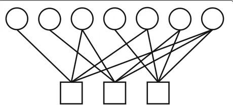
The associated graph is shown in Fig.1. Each of the cir-cles is a variable node corresponding to a column in H. Each of the squares is a parity-check node corresponding to a row inH. There is a connection, edge, between the variable nodeiand parity-check nodejifHij=1.
An LDPC code is said to be regular if the degree of all parity-check and variable nodes in the graph is the same, i.e., the degree distribution is uniform; otherwise, the code is irregular.
Encoding can be performed using thek×ngenerator matrixGwhose rows form a basis forC. The data word d∈Fk2is encoded as:
x=GTd∈C. (3)
The Hamming distance, d(x1,x2), between any two codewords x1andx2 ∈ C is the number of vector ele-ments in which they differ. A code’s minimum Hamming distance is then:
dm(C)=min({d(x1,x2):x1,x2∈C}). (4) The weight of a codeword x ∈ C, w(x), is the Ham-ming distance between it and the all zero codeword0, i.e., w(x) = d(0,x). The minimum weight of a code is then naturally defined as:
wm(C)=min({d(0,x):x∈C}). (5) AsCis a linear space, it follows thatdm(C)=wm(C). For transmission, codewords are binary phase-shift key-ing (BPSK) modulated with the mappkey-ing{0, 1} → {1,−1}. Denoting the modulated codeword vector asxm∈Rn2, the received vectory∈Rn2is:
Fig. 1Tanner graph example. Tanner graph for the (7,4) Hamming code. Circles are variable nodes, and squares are parity-check nodes. Nodes are connected via edges according toH
y=xm+n, (6)
where n ∈ Rn2 is the noise vector. For additive white Gaussian noise (AWGN)ni = N0,σ2 , whereσ2is the variance of the noise. The magnitude of which relative to the transmitted signal is quantified by the signal-to-noise (SNR) ratio [16]:
Eb/N0= (¯ xm)2i
2Rσ2, (7)
where(x¯m)2i is the average power of a transmitted bit. The decoder will attempt to determine the transmitted codeword given the received signal. An ideal maximum a posteriori (MAP) decoder would output the most likely codewordx˜given the received signal, i.e.,
˜
x=maxxP(x|y). (8)
However, MAP decoding for LDPC codes is NP hard [17]. As a result, the approximate method of belief prop-agation (BP) is employed [18]. BP is an iterative local neighborhood message-passing algorithm, where in each iteration, a set of messages are passed between variable and check nodes. The first step is to calculate the a priori log-likelihood ratio (LLR) values for each received bit:
i=ln
P(yi|xi=0) P(yi|xi=1)
, (9)
for the AWGN channel this reduces to i=
2yi
σ2. (10)
Ifri>0, then it is more likely thatxi =0; conversely, if ri < 0, then it is more likely thatxi = 1. As such, a first estimate of the transmitted codeword can be made where
˜ xi=
1 2
1− i |i|
. (11)
If Hx˜ = 0, then decoding is complete, if not then an iterative process commences. First, a message is sent from all variable nodes to their connected check nodes. The message is sent from variable nodevito check nodecj
Qi,j=i+
ca∈N(vi)\cj
Ra,i, (12)
whereN(vi)\cjis the set of check nodes connected tovi except forcj itself. Note that in the first iteration,Rj,i = 0∀i,j. Next, a message is sent from all check nodes to their connected check nodes. The message sent from check nodecjto variable nodeviis:
Rj,i=2 arctanh
⎛
⎝
vb∈N(cj)\vi tanh
Qb,j 2
⎞
⎠. (13)
Finally, the marginal LLR values are updated for each bit: Li=i+
ca∈N(vi)
[image:2.595.60.290.590.695.2]These values can then be used to make a new estimate at the transmitted codeword:
˜ xi= 1
2
1− Li |Li|
. (15)
If Hx˜ = 0, then decoding is complete, if not then another iteration commences.
There are three possible decoding outcomes. The first outcome is a correct decoding where x˜ = x. Second is a detected error where some maximum number of itera-tions is reached withx˜ = xbecause Hx˜ = 0. The last case is an undetected error where the decoder terminates becauseHx˜=0, butx˜=x.
BP will achieve MAP decoding in the case of the graph having a tree structure. However, the graphs of LDPC codes are typically not trees (if a code’s graph is a tree, then the code must contain weight two codewords [19]). A loop is a closed walk with no repeated edges or nodes. The size of a loop is the number of edges traversed (always even for a bipartite graph), and the girth of a given code is defined as the size of the smallest loop in the graph.
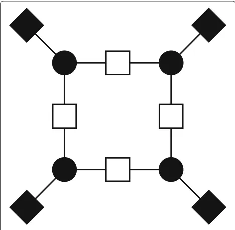
The set of variable nodes that do not converge to the correct value in decoding is denotedT(y)[20]. IfT(y)= ∅ then leta = |T(y)| andbbe the number of odd degree check nodes in the sub-graph induced byT(y)(the sub-graph contains T(y) and connected check nodes) then T(y)is a(a,b)trapping set. An example of a (4,4) trapping set is shown in Fig.2.
The frame error rate (FER) performance of a decoder is divided into three regions, these can be clearly seen
Fig. 2Trapping set example (4,4) trapping set example. The black variable nodes have failed to converge, and thus, the black (odd degree) check nodes are unsatisfied. The white (even degree) nodes are satisfied
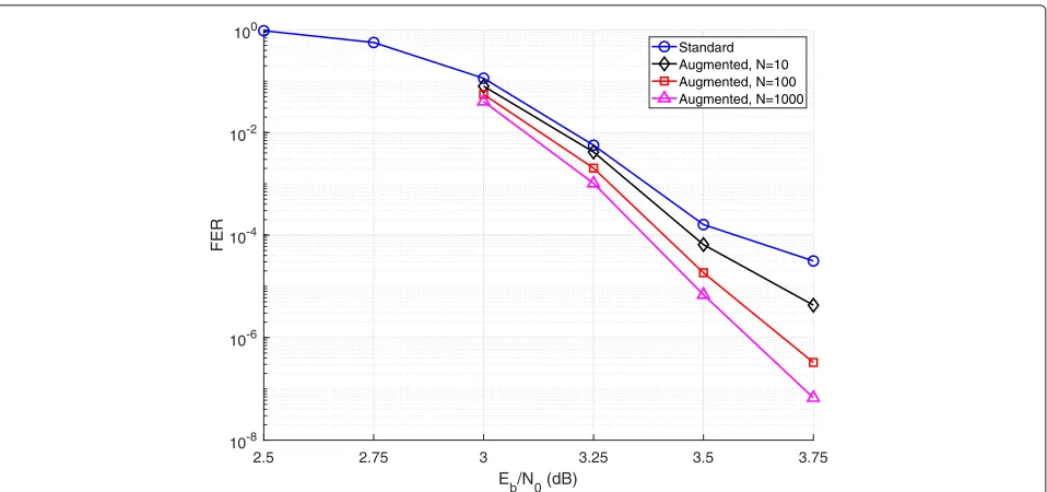
in Fig. 3. The first region is at low SNR where the decoder fails to decode the majority of the frames. As SNR increases, there is a rapidly decreasing FER in the water-fall region. Then at higher SNR, the FER decreases at a reduced rate; this is the error floor region. This error floor can either be due to the undetected errors (a result of low-weight codewords) or detected errors. In the second case, the error floor can be lowered by mitigating trapping sets; this is the aim of the augmented decoder.
3 Method
3.1 Parity-check formulation
Graph augmentation aims to mitigate the effect of trap-ping sets in the graph by iteratively duplicating a subset of parity checks. An augmented decoder employs a set of modified or augmented parity-check matrices, called the candidate set. Each of the candidates in the set has the form:
HA=
H Hd
, (16)
whereHis the original (given) parity-check matrix andHd is adn×nmatrix containingdnrows randomly selected fromH.dis called the augmentation density.
On the graph forHA, the augmentation defined above corresponds to a duplication of a subset of parity-check nodes (of the original graph). The candidate set contains N-augmented matrices denoted by:
=HA1,HA2, . . .,HAN. (17)
The operation of the augmented decoder is outlined in Algorithm 1. Decoding is first attempted on the standard graph (not augmented). If this decoding step is unsuc-cessful, then decoding is reattempted using an augmented candidate graph until either decoding is successful or the candidate set is exhausted.
Algorithm 1Operation of an augmented decoder. Attempt decoding usingH
ifx˜H=0 then i=1
decoded=false
whilei<Nand !decodeddo Attempt decoding usingHAi. ifx˜HAi =0 then
decoded=true Outputx˜ i=i+1 else
[image:3.595.57.291.461.690.2]2.5 2.75 3 3.25 3.5 3.75
E b/N0 (dB)
10-8 10-6 10-4 10-2 100
FER
Standard Augmented, N=10 Augmented, N=100 Augmented, N=1000
Fig. 3Quasi-regular FER plot. FER performance of augmented decoders for then=4095,R=0.82 quasi-regular code
As the duplicated rows in each candidate are selected randomly, it is possible to generate candidates as they are required. Furthermore, it is possible to vary the augmenta-tion density depending on SNR. Secaugmenta-tion4.1demonstrates that this can lead to improved performance.
3.2 BP formulation
The effect of duplicating a subset of parity checks can also be considered as a modification of BP on the code’s origi-nal graph (i.e., with no duplicated checks). First, we define a function that indicates whether a check node has been duplicated:
r(j)=
1 ifcjduplicated
0 ifcjnot duplicated. (18)
The equivalent variable to check node message on the original graph is then:
Qi,j=i+
ca∈N(vi)\cj Ra,i+
1
2r(j)Rj,i, (19)
and the check to variable node message is:
Rj,i=2arctanh
⎛
⎝
vb∈N(cj)\vi tanh
Qb,j 2
⎞
⎠ 1+rj .
(20)
It can be seen that the effect of duplicating a check node is to double the magnitude of the messages it sends in our modified BP. It can also be seen that the message sent from variable nodevito check nodecjis no longer independent
of the message sent fromcjtoviin the previous iteration, i.e., feedback has been introduced.
This feedback and message amplification alters the rate at which the marginal probabilities converge. Reliable information from the fast converging variable nodes can then propagate to other variable nodes (via check nodes). Variable nodes will converge in different orders depending on which checks have been duplicated, this can potentially lead to avoiding a trapping set that occurs when using standard BP.
Implementing augmentation as a modification to BP means that there is no complexity overhead for each iteration. However, implementing it based on duplicated rows in the parity-check matrix allows for an efficient pre-existing BP decoder to be used.
4 Numerical results
4.1 Quasi-regular Mackay
The first code considered is ann = 4095 andR = 0.82 quasi-regular code [21]. The error floor of this code when using the standard belief propagation decoder is shown in Fig.3.
To find the optimal augmentation density, decoders withN =100 candidates of varyingdwere tested at four SNR values as shown in Fig.4. It can be seen that at higher SNR (in the error floor region), the FER reduction of the augmented decoder is more pronounced than at lower SNR (in the waterfall region). Furthermore, it can be seen that as SNR increases, the optimal augmentation density also increases.
[image:4.595.60.539.85.310.2]10-2 10-1 100
d
10-7 10-6 10-5 10-4 10-3 10-2 10-1 100
FER
3 dB 3.25 dB 3.5 dB 3.75 dB
Fig. 4Quasi-regular density plot. FER performance of an augmented decoder withN=100 candidates with varying augmentation densitydfor the n=4095 andR=0.82 quasi-regular code
The augmentation density of these decoders is selected to be the optimal values shown in Fig.4, 4% at 3 dB, 5.7% at 3.25–3.5 dB, and 23% at 3.75 dB. With 1000 candidates at 3.75 dB, approximately half the errors are undetected errors due to weight 10–14 codewords, i.e., this is the start of a low-weight codeword error floor.
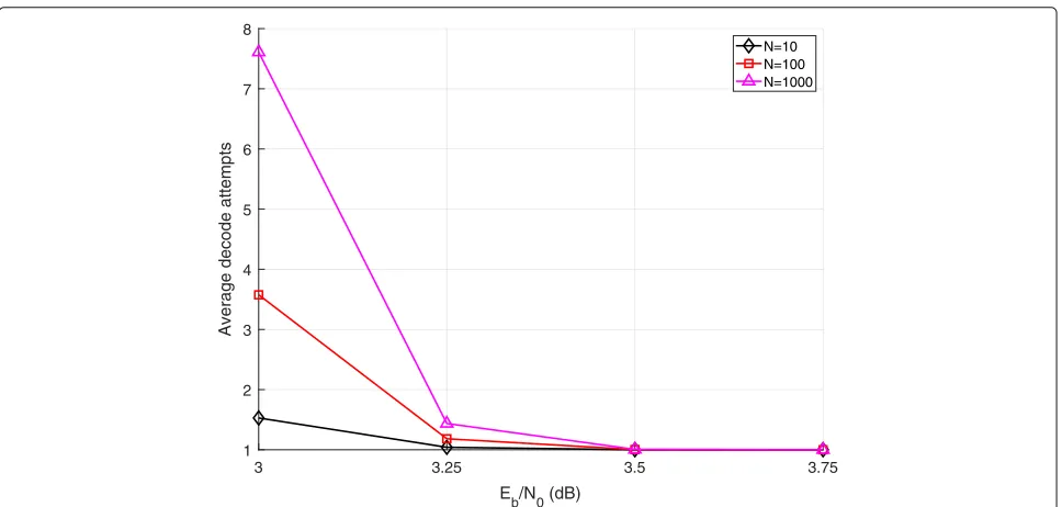
The average number of decoding attempts (including the initial standard BP attempt) is shown in Fig.5. It can be
seen that at higher SNR, the increase in the average num-ber of decoding attempts is negligible, this is due to the two factors. Firstly, at higher SNR, the standard decoder is able to decode more frames, as such the likelihood that any candidates are required is reduced. Secondly, the average number of candidates required to decode a frame which cannot be decoded using standard BP reduces as SNR increases.
3 3.25 3.5 3.75
Eb/N0 (dB)
1 2 3 4 5 6 7 8
Average decode attempts
N=10 N=100 N=1000
[image:5.595.58.539.86.313.2] [image:5.595.58.542.471.702.2]1.4 1.6 1.8 2 2.2 2.4 2.6 2.8 3 3.2 3.4
Eb/N0 (dB)
10-10 10-8 10-6 10-4 10-2 100
FER
Standard Backtracking Augmented, N=10 Augmented, N=100 Augmented, N=1000
Fig. 6n=1056 WiMAX FER plot. FER performance of augmented decoders for then=1056 andR=1/2 WiMAX code. Also shown is the performance of a backtracking decoder
4.2 WiMAX
4.2.1 n=1056and R=1/2code
The second code considered is then=1056 andR=1/2 quasi-cyclic LDPC (QC-LDPC) code from the IEEE 802.16e WiMAX standard [22]. Here, augmentation is compared to the second backtracking method presented in [9]. As is shown in Fig.6, the decoder with backtracking has similar waterfall performance to the standard BP decoder but a significantly improved error floor.
Augmented decoders with N = 10, N = 100, and N=1000 candidates were tested. The augmentation den-sity used at each SNR was optimized in the same way as for the quasi-regular code of Section4.1. These den-sities are 4% for 1.4–1.8 dB, 5.7% for 2–2.2 dB, 8% for 2.4–3 dB, and 11% for 3.2–3.4 dB. It can be seen that the augmented decoders provide a significant gain in water-fall FER. Furthermore, decoding based on augmentation reaches an error floor due to low-weight (mostly weight
2.2 2.4 2.6
E b/N0 (dB)
10-4 10-3 10-2
FER
Standard MBBP, l=7 MBBP, l=15 L-MBBP, l=30 Augmented, N=7 Augmented, N=15 Augmented, N=30
[image:6.595.59.538.87.308.2] [image:6.595.56.540.478.702.2]1 1.25 1.5 1.75 2
Eb/N0 (dB)
10-7 10-6 10-5 10-4 10-3 10-2 10-1 100
FER
Standard ANS
Augmented, N=10 Augmented, N=100 Augmented, N=1000
Fig. 8802.11n FER plot. FER performance of augmented decoders for then=1944 andR=1/2 802.11n code. Also shown is the performance of a ANS serial decoder
21) codewords at a significantly lower SNR than the back-tracking decoder. At 3.4 dB, over 95% of the errors found using 1000 candidates are undetected, as such the FER cannot be further reduced.
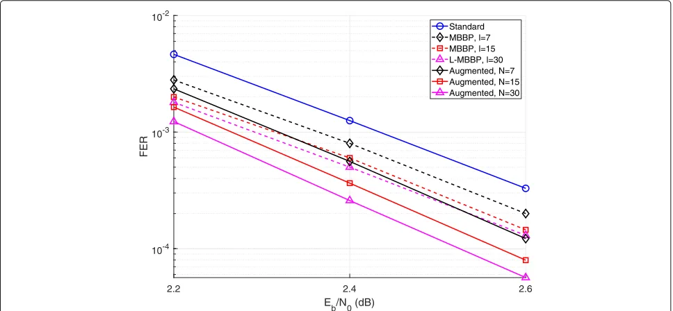
4.2.2 n=576and R=1/2code
The third code considered is the n = 576 and R = 1/2 QC-LDPC code from the WiMAX standard. Here,
augmentation is compared to the multiple-bases belief-propagation (MBBP) and leaking MBBP (L-MBBP) [8]. This comparison is important as both the augmented decoder and the MBBP decoder make use of a set of parity-check matrices at the decoder. For this reason, we selected the size of the candidate set to be identical to the number of parity-check matrices used by Hehn et al. in [8]. An augmentation density of 5.7% was used at all
1.7 1.9 2.1 2.2 2.3
Eb/N0 (dB)
10-8 10-7 10-6 10-5 10-4 10-3 10-2
FER
Standard ANS Backtracking G-LDPC
Schedule diversity, T=4 Augmented, N=10 Augmented, N=100 Augmented, N=1000
[image:7.595.61.539.86.312.2] [image:7.595.58.539.477.701.2]SNR values. The results are shown in Fig.7, indicating that graph augmentation yields a lower FER when compared to the MBBP and L-MBBP methods. Approximately, a third of the errors found at 2.6 dB using the decoder based on 30 candidates are undetected; this suggests that there will be a low-weight (mostly weight 13) error floor at higher SNR.
4.3 802.11n
The fourth code considered is the n = 1944 andR = 1/2 code from the IEEE 802.11n standard [23]. This code has similar construction to the WiMAX code. Here, augmentation is compared to the performance of the approximate node-wise scheduling (ANS) serial decoder presented in [12]. It can be seen in Fig.8 that the serial decoder performs similarly to the standard flooding-based decoder in the waterfall region. However, serial decoding provides an improved FER in the error floor region.
Augmented decoders with N = 10, N = 100, and N=1000 candidates were tested. The augmentation den-sities used were 2% at 1–1.25 dB, 2.8% at 1.5–1.75 dB, and 5.7% at 2 dB. It can be seen that the decoder with ten candidates gives similar performance to the serial decoder and that the decoders with 100 and 1000 candi-dates give significantly better performance. At 2 dB, the augmented decoder based on 1000 candidates produces more undetected than detected errors; this suggests that it will present a low-weight (ranging in weight from 27–40) codeword error floor beyond this point.
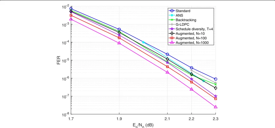
4.4 Margulis
The final code considered is then = 2640 andR = 1/2 Margulis code [24]. This is a protograph-based code, and here, augmentation is compared to the performance of a serial decoder employing schedule diversity [14] (note that this type of decoder only works for protograph-based codes). This decoder first attempts decoding with an opti-mized message passing schedule; if decoding fails, then it iteratively reattempts decoding using a scrambled sched-ule up to a maximum ofTattempts. The performances of approximate node-wise scheduling (ANS), backtracking, and G-LDPC decoders are also given for this code (these are also taken from [24]).
Augmented decoders withN =10,N = 100, andN = 1000 candidates were tested, and the results are shown in Fig.9. An augmentation density of 2% was used at all SNR values considered. It can be seen that at 2.3 dB, the aug-mented decoder with ten candidates is able to outperform the backtracking and G-LDPC decoders and gives similar performance to the ANS decoder. The schedule diversity decoder has a performance between that of an augmented decoder with 10 candidates and one with 100 candidates (it can be matched by using approximately 35 candidates).
5 Conclusions
We proposed the use of a decoder based on graph aug-mentation for mitigating trapping sets and thus error floors in LDPC codes. The performance of the proposed decoder was tested through computer simulation on a number of different LDPC codes (both regular and irregu-lar). In all cases, the augmented decoder provided a lower error floor frame error rate than other modified belief propagation decoders presented in the literature.
Abbreviations
ANS: Approximate node-wise scheduling; AWGN: Additive white Gaussian noise; BP: Belief propagation; BPSK: Binary phase-shift keying; FER: Frame error rate; G-LDPC: Generalized LDPC; LDPC: Low-density parity-check; LLR: Log-likelihood ratio; L-MBBP: Leaking MBBP; MAP: Maximum a posteriori; MBBP: Multiple-bases belief-propagation; PEG: Progressive edge-growth; QC-LDPC: Quasi-cyclic LDPC; SNR: Signal-to-noise ratio
Authors’ contributions
ARR contributed 50%, and all other authors contributed an equal 12.5%. All authors read and approved the final manuscript.
Competing interests
The authors declare that they have no competing interests.
Publisher’s Note
Springer Nature remains neutral with regard to jurisdictional claims in published maps and institutional affiliations.
Author details
1College of Sciences and Engineering, University of Tasmania, Hobart, Australia.2Department of Electrical Engineering, University of Pretoria, Pretoria, South Africa.3Department of Electrical and Computer Engineering, Lehigh University, Bethlehem, USA.
Received: 24 January 2018 Accepted: 17 July 2018
References
1. R Gallager, Low-density parity-check codes. IRE Trans. Inf. Theory.8(1), 21–28 (1962)
2. T Richardson, inError floors of LDPC codes. Proceedings of the Annual Allerton Conference on Communication Control and Computing, vol. 41 (University of Illinois, Curbana-Champaign, 2003), pp. 1426–1435. The University; 1998
3. TJ Richardson, MA Shokrollahi, RL Urbanke, Design of
capacity-approaching irregular low-density parity-check codes. IEEE Trans. Inf. Theory.47(2), 619–637 (2001)
4. X-Y Hu, E Eleftheriou, D-M Arnold, inProgressive edge-growth Tanner graphs. Global Telecommunications Conference, 2001. GLOBECOM’01. IEEE, vol. 2 (IEEE, San Antonio, 2001), pp. 995–1001
5. DV Nguyen, SK Chilappagari, MW Marcellin, B Vasic, On the construction of structured LDPC codes free of small trapping sets. IEEE Trans. Inf. Theory.58(4), 2280–2302 (2012)
6. O Fainzilber, E Sharon, S Litsyn, inDecreasing error floor in LDPC codes by parity-check matrix extensions. Information Theory, 2009. ISIT 2009. IEEE International Symposium On (IEEE, Seul, 2009), pp. 374–378 7. Y Han, WE Ryan, Low-floor decoders for LDPC codes. IEEE Trans.
Commun.57(6), 1663–1673 (2009)
8. T Hehn, JB Huber, S Laendner, inImproved iterative decoding of LDPC codes from the IEEE WiMAX standard. Source and Channel Coding (SCC), 2010 International ITG Conference On (IEEE, Siegen, 2010), pp. 1–6
9. J Kang, Q Huang, S Lin, K Abdel-Ghaffar, An iterative decoding algorithm with backtracking to lower the error-floors of LDPC codes. IEEE Trans. Commun.59(1), 64–73 (2011)
10. J Hamkins, inPerformance of low-density parity-check coded modulation. Aerospace Conference, 2010 IEEE (IEEE, Big Sky, 2010), pp. 1–14 11. X Zhang, PH Siegel, Quantized iterative message passing decoders with
12. AIV Casado, M Griot, RD Wesel, LDPC decoders with informed dynamic scheduling. IEEE Trans. Commun.58(12), 3470–3479 (2010)
13. X Liu, Z Zhou, R Cui, E Liu, Informed decoding algorithms of LDPC codes based on dynamic selection strategy. IEEE Trans. Commun.64(4), 1357–1366 (2016)
14. H-C Lee, Y-L Ueng, LDPC decoding scheduling for faster convergence and lower error floor. IEEE Trans. Commun.62(9), 3104–3113 (2014) 15. E Cavus, B Daneshrad, inA performance improvement and error floor
avoidance technique for belief propagation decoding of LDPC codes. Personal, Indoor and Mobile Radio Communications, 2005. PIMRC 2005. IEEE 16th International Symposium On, vol. 4 (IEEE, Berlin, 2005), pp. 2386–2390
16. DJ MacKay,Information theory, inference and learning algorithms. (Cambridge University Press, Cambridge, 2003)
17. E Berlekamp, R McEliece, H Van Tilborg, On the inherent intractability of certain coding problems (corresp.) IEEE Trans. Inf. Theory.24(3), 384–386 (1978)
18. DJ MacKay, Good error-correcting codes based on very sparse matrices. IEEE Trans. Inf. Theory.45(2), 399–431 (1999)
19. T Richardson, R Urbanke,Modern coding theory. (Cambridge University Press, New York, 2008)
20. B Vasi´c, SK Chilappagari, DV Nguyen, SK Planjery, inTrapping set ontology. Communication, Control, and Computing, 2009. Allerton 2009. 47th Annual Allerton Conference On (IEEE, Monticello, 2009), pp. 1–7 21. Encyclopedia of Sparse Graph Codes, Code 4095.737.3.101.http://www.
inference.org.uk/mackay/codes/data.html. Accessed 30 June 2016 22. IEEE Standard for Local and metropolitan area networks Part 16: Air
Interface for Broadband Wireless Access Systems. IEEE Std 802.16-2009 (Revision of IEEE Std 802.16-2004), 1–2080 (2009).https://doi.org/10. 1109/IEEESTD.2009.5062485
23. IEEE Standard for Information technology–Telecommunications and information exchange between systems Local and metropolitan area networks– Specific requirements - Part 11: Wireless LAN Medium Access Control (MAC) and Physical Layer (PHY) Specifications. IEEE Std 802.11-2016 (Revision of IEEE Std 802.11-2012), 1–3534 (2016).https://doi. org/10.1109/IEEESTD.2016.7786995