Cost Efficient Overflow Routing for Outbound ISP Traffic
Alexander A. Kist and Richard J. Harris
RMIT University, BOX 2476V, Victoria 3001, Australia
Email: [email protected], [email protected]
Abstract
Multihomed Internet Service Providers (ISPs) are typi-cally connected to several transit ISPs. If cost is assigned to interconnecting resources, multihomed ISPs face the prob-lem of cost efficient outbound traffic routing. In particular, this is relevant if the ISPs form customer to provider rela-tionships and alternative billing schemes are used, i.e. vol-ume or time based. The Border Gateway Protocol (BGP) is the de facto standard for inter-domain IP routing on the Internet but its traffic engineering capabilities are limited. This paper proposes a local overflow methodology that al-lows cost efficient outbound packet routing and is based on the Scheme for Alternative Packet Overflow Routing (SAPOR). The paper identifies the underlying optimisation problem, introduces the modified SAPOR methodology and presents simulation results that verify the operation of the scheme.
1. Introduction
The Internet consists of a vast number of interconnected domains or networks. A domain is usually associated with a company, an organisation or an Internet Service Provider (ISP). Two principal ISP types are common, stub ISPs and transit ISPs. Stub ISPs resell Internet connectivity to third parties such as home users and businesses, as well as ser-vice hosts, content and web space providers etc. Generally, stub ISPs provide no transit services. Transit ISPs provide connectivity to other ISPs and organisations. Stub ISPs re-quire transit ISPs to gain connectivity to the global Internet. Whereas the main purpose of transit ISPs is to transport traf-fic, stub ISPs consume and/or generate traffic. Two com-mon business relationships exist: customer-to-provider or peer-to-peer relationships. Where providers sell resources, peers make resources available to each other’s customers. The Internet hierarchy and its characterisation is discussed in [1] in more detail.
To route IP packets between domains, inter-domain
rout-ing protocols are used. The Border Gateway Protocol
(BGP) [2] is the de facto inter-domain routing standard on the Internet. In BGP jargon, domains are called Au-tonomous Systems (ASs). BGP is a path vector protocol that propagates reachability information of networks and distributes paths to all reachable ASs. Due to the massive growth of the Internet, BGP faces a number of known prob-lems: Route instabilities, convergence, scalability and rout-ing inefficiencies. These issues are well known by the re-search community and are not the immediate focus of this work. However, in this paper, it is assumed that gateway routers use BGP.
BGP provides certain rules that influence traffic flows and their routing. The article [3] by B. Quoitin et al. and the book [4] by I. van Beijnum (Chapter 6: Traffic Engi-neering) are examples that address this topic. These works discuss methods for influencing the network exit strategy for outbound traffic, but these schemes are not load sensi-tive and most of the methods rely on the manipulation of prefix matching and routing tables. Inbound traffic routing depends, to a large extent, on policies that are implemented by upstream ISPs. To some extent this can be influenced by the advertised routes. Recent research addresses this topic. For example, B. Quoitin et al. propose in [5] redistribution communities to control inbound traffic.
Internet backbones and transit networks are often oper-ated by commercial service providers. ISPs that connect to these domains require commercial Service Level Agree-ments (SLAs). If dollar-costs are associated with usage, op-timisation techniques can be used to minimise operational costs. These techniques result in the choice of the most cost efficient path for given settings. A recent paper by Uhlig et al. [6] addresses the problem of intra-domain traffic en-gineering by using an evolutionary algorithm to find near optimal BGP filters that balance the load over several inter-faces. Another possible traffic engineering method is over-flow routing.
Rout-ing (DNHR) which uses different path sets for different times of the day for voice carriers and was initially devel-oped by AT&T. In a recent paper [8], a Scheme for Alterna-tive Packet Overflow Routing (SAPOR) has been introduced which provides a mechanism for overflow routing in IP net-works. SAPOR mainly targets interior gateway routing. This paper proposes an adaptation of the SAPOR scheme to address the problem of cost efficient stub AS outbound traffic routing in BGP contexts.
The discussions in this paper use the notion of flows to discuss the network traffic. Microflows are defined as a collection of packets with the same source and destina-tion address, the same source and destinadestina-tion ports and are separated by interarrival times that are below a maximum threshold. Flows are the aggregation of microflows. Both are measured in bytes per second.
The contributions of this work can be summarised as fol-lows: Firstly, it outlines the optimisation problem of effi-cient traffic routing for outbound ISP traffic; secondly, it proposes a modified SAPOR scheme that allows cost effi-cient overflow routing in IP networks; and thirdly, it pro-vides simulation results that verify the operation of this scheme.
The paper is organised as follows: The next section dis-cusses the general optimisation problem and its relevance, Section 3 introduces the modified SAPOR scheme in de-tail. Section 4 discusses the proposed scheme and Section 5 gives simulation results and a performance analysis of the scheme.
2. The Optimisation Problem
ISPs with client to (service) provider relationships face the problem of cost efficient outbound traffic routing. This is particularly important for ISPs when alternative costing methods are available. Two billing schemes (and their com-bination) are widely used to account for costs applicable to connecting networks to upstream providers: A time based (monthly/weekly/daily) rate for fixed capacity connections or volume based charges as in dollars per GB (MB). The case where both subscription types are available to ISPs si-multaneously, results in an optimisation problem: Minimise the cost of routing a given traffic volume via a set of out-bound links.
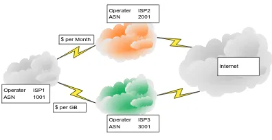
Figure 1 depicts an example of such a setup. The stub ISP, ISP1, is multihomed. It has a customer-to-provider re-lationship with ISP2 and ISP3. Both, ISP2 and ISP3, pro-vide connectivity to the remaining Internet. It is assumed that most destinations are reachable via both providers, but limitations in connectivity can be resolved by BGP. The connection of ISP1 to ISP2 is billed on a time basis and the connection of ISP1 to ISP3 is billed on a volume basis.
Internet Operater ISP2
ASN 2001
Operater ISP1 ASN 1001
Operater ISP3 ASN 3001 $ per Month
[image:2.612.338.536.69.171.2]$ per GB
Figure 1. ISP Example
This situation can be formulated as a Mixed Integer Lear Program (LP) with the following variables: Link
in-dicesi, microflow indicesj, capacity of linki-ui, the
vol-ume proportional cost of linkiper unit flow -αi, the fixed
cost of linki-βi, the flow size on linki-fi, flow on link
ithat incurs no cost -gi, size of microflowj-dj, the
traf-fic volumeV, the decision variablexij - is “1”, if flowj
is routed on linkiotherwise it is “0” and the decision
vari-ableyi- is “1” if linkiis used otherwise it is “0”. The LP
formulation with the linear cost functionci(fi)is:
Minimise:C=X
i
yici(fi) (1)
Where the cost function is defined as:
ci(fi) =max{βi, βi+αi(fi−gi)} ∀i= 1. . . imax (2)
Subject to the following constraints: Flow on linkidoes not
exceed the link capacity.
fi= X
j
djxij ≤ui ∀i= 1. . . imax (3)
All flows have to be routed.
X
i
yifi≥V (4)
Flows can not be split.
X
i
xij = 1 (5)
Zero-one variables, demands and cost are positive.
xij, yi∈ {0,1};fi, gi, bi, ci≥0 (6)
If microflows have to be routed on certain links, the capacity of these links is reduced and the LP formulation uses the remaining bandwidth.
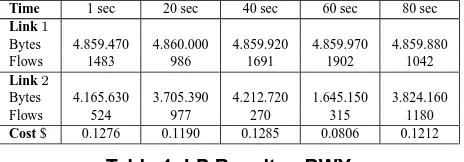
Time 1 sec 20 sec 40 sec 60 sec 80 sec
Link1
Bytes 4.859.470 4.860.000 4.859.920 4.859.970 4.859.880
Flows 1483 986 1691 1902 1042
Link2
Bytes 4.165.630 3.705.390 4.212.720 1.645.150 3.824.160
Flows 524 977 270 315 1180
[image:3.612.320.555.71.158.2]Cost $ 0.1276 0.1190 0.1285 0.0806 0.1212
Table 1. LP Results - BWY
should be routed via the variable rate link. Practical prob-lem formulations might have additional constraints produc-ing an extended LP.
As an example, the above LP was solved for two links
with the following parameters: Link 1 had a time based
cost of b1 = $0.05/sec associated with it and link 2
had a volume based cost ofc2 = $20/GByteassociated
with it. The available capacity of both links was set to 4,860,000Bytes/sec. Publicly available IP trace data [9]
was used to generate the flow information1. Two data sets
were used: One trace was collected at the Columbia Uni-versity gateway in New York (BWY) the other one was collected at the Colorado State University gateway (COS). Both traces involve about 90 seconds worth of data and were collected commencing at 23/10/03 - 10:31:37 and at 5/11/03 - 14:10:22 respectively. The optimal flow alloca-tions were calculated for microflow samples that were ac-cumulated over one second.
Table 1 and Table 2 depict selected sample LP results for the BWY and the COS trace, respectively. The column present the data at time index 1 sec, 20 sec, etc., the rows indicate flow size, the number of microflow flows and the overall cost. The BWY trace consist of lager microflows and almost use the full capacity of both links, the COS trace consists of more, smaller size, microflows and uses only a fraction of the overflow capacity of link 2.
The results show for both traces that the available ca-pacity on link 1 (time based cost) is used in all cases up to
its capacity limit (4,860,000Bytes/sec). Additional
mi-croflows are routed on link 2 with a volume based cost. These results confirm the expectation that the solution in this situation resembles an overflow case for minimum cost routing: The fixed cost path is used as much as possible.
Note that the LP formulation addresses only a static case at one point in time and that it is also assumed that all the de-mands are known beforehand. In particular, flows arrive and depart and are of different and variable size. However, the principal problem formulation and solution remains also for the dynamic case. It results in a dynamic overflow situation: Use the fixed cost resources for as much traffic as possible
1The used traces are of high-bandwidth links that were not fully
utilised. Therefore, the traffic was determined by bottlenecks in other parts of the network. As long as the traffic flows are only redirected on links with similar characteristics and no additional packets are dropped, this trace driven observations provide relevant results.
Time 1 sec 20 sec 40 sec 60 sec 80 sec
Link1
Bytes 4.859.970 4.859.970 4.859.990 4.859.960 4.859.990
Flows 2766 2895 2811 2194 2610
Link2
Bytes 1.167.800 632.934 572.579 1.184.050 1.055.230
Flows 661 370 167 363 437
Cost 0.0718 0.0618 0.0607 0.774 0.0697
Table 2. LP Results - COS
and overflow additional traffic to variable cost paths. Where the theoretical formulation and the solution of the problem appear to be straight forward, the practical imple-mentations of these results with BGP is non trivial. A num-ber of BGP based traffic engineering initiatives rely on the tuning of BGP’s decision process. These efforts can be only executed in limited time intervals and are static between these updates.
If, for a given gateway the demands are known, the flow assignment can be calculated by the LP and BGP filters can be changed to take the LP results into account. This strategy has two problems: firstly it is difficult to measure and pre-dict the traffic on a microflow level and secondly the prob-lem size scales badly for many frequently changing flows. Several aggregations can be used but, in any case, traffic directing relies on prefix matching.
An alternative to this that overcomes the problems is a scheme that assigns microflows according to the constraints and simultaneously minimises cost on the fly. The overflow scheme that is introduced in the next section relies on BGP to find the appropriate destinations, but it extends routers by a dynamic traffic routing capability.
3. Adapted SAPOR Scheme
The scheme for alternative packet routing originally tar-geted overflow routing in Interior Gateway Protocol (IGP) environments, this section describes an adapted scheme that suit the problem of outbound AS traffic overflow routing.
SAPOR implements three principles: Firstly it ensures that packets that belong to the same microflow are routed on the same interface, even in the overflow case. Secondly it determines how many additional microflows can be ac-commodated by the default link before it’s target bandwidth is reached. And thirdly, if the target bandwidth is reached, additional flows are routed on alternative interfaces.
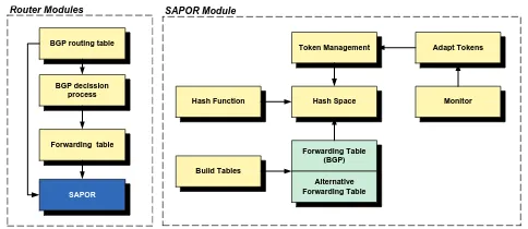
[image:3.612.65.297.72.153.2]BGP routing table
Forwarding table BGP decission
process
SAPOR
Router Modules SAPOR Module
Hash Function Hash Space
Forwarding Table (BGP)
Alternative Forwarding Table Token Management
Monitor
Build Tables
Adapt Tokens
Figure 2. (a) Router - (b) SAPOR Scheme
will have alternative paths, in particular, if the AS is multi-homed.
BGP’s decision process builds the forwarding table by the use of policies. Factors that have an impact on this pro-cess include Multi Exit Discriminator (MED), local pref-erence, shorter autonomous system paths, etc. (e.g. [10]). Forwarding tables have usually one entry per destination. If BGP multipath is supported, alternative paths to one des-tination are possible. If more than one path is used, the load is balanced between alternative destinations. SAPOR facilitates BGP’s forwarding and original routing tables as inputs.
The operation of SAPOR can be summarised as follows: Packets are classified to identify microflows and if packets belong to microflows that already exist, they are forwarded on the same interface that the first packet saw in the scheme. If packets belong to a new flow and tokens are available for this destination, the outgoing interface is chosen on the ba-sis of the original forwarding table. If no tokens are avail-able the overflow-forwarding tavail-able is consulted and pack-ets are forwarded on alternative interfaces. All subsequent packets that belong to the same microflow will use the same interface for the duration of the microflow. The number of tokens that are available for one interface determines the number of microflows that are allowed. SAPOR uses the original BGP routing table to determine the default routing and uses alternative routing tables for overflow traffic.
Figure 2 (b) depicts the function blocks of such a SAPOR module. These are: hash function, hash space, token man-agement, adapt token, monitor, forwarding tables and build-tables function. The modules have to execute two major tasks: Identify microflows and determine available capac-ity, i.e. the number of additonal microflows on a link.
3.1. Identifying Microflows
To ensure that packets that belong to the same microflow are routed on the same link, microflows have to be iden-tified. This is done by the hash function. It calculates hash values on the origin/destination address/port. The hash
function has to yield hash valuesH(.)that are unique and
evenly distributed over the hash space2.
The hash function points to one unique element in the non-overlapping hash space. Elements are associated with given microflows and hold tokens that identify the interface where packets of to this microflow should exit the router. To detect flows that are no longer active, elements have timer values that indicate if the element was visited during a cer-tain period. Tokens are used to identify the interface and also determine the maximum number of flows on a given link.
3.2. Token Management
The number of tokens defines the number of microflows that are allowed on one interface and the token management function accounts for the number of tokens. Every inter-face has a token buffer associated with it. The number of available tokens in the buffer is the estimated number of additional flows that the associated interface can accommo-date, before it reaches the target bandwidth. This number has to be adapted during each measurement/update interval. If new microflows arrive, the token number of the interface is reduced by one for each microflow. To detect flows that are no longer active, a token scheduler has to return expired tokens to the appropriate buffers.
The size of microflows differs between active flows. Large flows consist of many packets and can be persistent for long periods (Elephants) and small flows consist of a few small packets (Mice). To account for this, the number of tokens has to be adapted. The adapt token function ad-justs the number of available tokens and the monitor func-tion measures the number of bytes that were transmitted via a interface since the last measurement. The accumulated flow size [bytes per adaptation interval] and the number of active flows are used to calculated the current average flow size. By using available bandwidth and average flow size, the remaining number of tokens can be estimated. This is shown in Equation (7)
ai= u
iti fi
−ti (7)
whereaiis the new number of available tokens for interface
i,uiis the target bandwidth,tiis the current token number
andfi is the current aggregated flow size that is provided
by the monitor function.
Note that available bandwidth refers to the remainder of the target bandwidth or the usable capacity. It is also im-portant to note that the number of tokens in a token buffer
2If the hash function used allows duplicates, collisions have to be
[image:4.612.58.300.70.175.2]can be negative. If the buffer size is changed on the fly and there are more tokens to be returned than the new buffer size indicates, the number of tokens is negative. Tokens are un-available from such a buffer as long as the number of tokens is less than or equal to zero.
3.3. Building Routing Tables
The build table function generates forwarding tables based on locally available information and is not a real-time function. It is executed when BGP routing tables are changed and local forwarding tables have to be adapted. The first table is a match of the original BGP forwarding table. The overflow table can be generated from the BGP routing table by the BGP decision process where paths that originally used the first interface, are ignored.
4. Remarks on the Overflow Scheme
This section discusses remarks that are relevant for the overflow scheme and that are not directly related to the other discussions in this paper. These include a microflow defini-tion, comments on performance requirements and possible failure scenarios.
4.1. Interarrival Times and Microflow Definition
The adapt token function can only adapt at the speed that new flows arrive or depart. If the flow definition interarrival
timetsuses shorter time intervals, the target bandwidth is
matched more easily than if the interarrival period is defined to be too long. To define a microflow for this scheme it is assumed that if packets arrive with larger interarrival times than 1 sec the interarrival time jitter is no major concern for this flow and the packets can be routed on alternative paths. To see how many microflows fall into this category the interarrival time of packets was investigated.
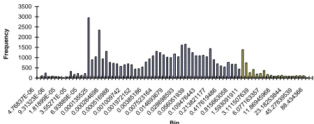
Figure 3 depicts a histogram for packet interarrival times for the COS trace that is used in this paper (See Sections 2 & 5). The y-axis shows the message count, the x-axis depicts the interarrival time bins in seconds using a loga-rithmic scale. The interarrival time was measured for two consecutive packets that had the same addresses and port numbers. 91% of the recorded interarrival events fall into the microflow definition. Analysis for the BWY trace (See Section 5) yields that 95% of the recorded events are below the one second threshold. In both cases most microflows are captured by a one second threshold.
4.2. Requirements and Performance
The complexity of this scheme has to be analysed for two parts: Operations that are required for packet routing
0 500 1000 1500 2000 2500 3000 3500
4.76837E-069.31323E-061.81899E-053.55271E-056.93889E-050.0001355250.0002646980.0005169880.0010097420.0019721520.003851860.0075231640.0146936790.0286985930.0560519390.1094764430.2138211770.4176194860.8156630581.5930919113.1115076396.07716335711.8694596823.1825384445.2783953988.434366
Bin
[image:5.612.325.550.70.159.2]Frequency
Figure 3. Histogram: Packet Interarrival Time
and functions that operate in an offline mode. All former
functions are of the order of one: O(1). This includes the
hash function, the test for tokens, the changes in the token
buffer, etc. Therefore, all packets are routed inO(1)time.
Forwarding table lookups might require additional time, but this is also required in conventional routing. If a
token-space has a assigned token, lessO(1)steps are required.
The offline operation is more complex but it is less fre-quently required. This includes the update of the tokens where all active hash spaces have to be traversed and the calculation of the overall token number. The complexity
of this process is boundedO(l), wherelindicates the size
of the hash space. Additional memory and intelligent data structures can reduce this requirement.
Memory requirements for routing tables etc. are equiv-alent to requirements for tables of legacy systems. Token buffers require only several bytes per buffer and the hash
space is of sizel. The next section discusses simulation
re-sults that verify the operation of the scheme.
4.3. Failure Scenario
If interfaces or their associated resources become un-available, the scheme has to respond to this situation. It has to react by immediately flushing the token buffer that is associated with the failing interface and by deleting all to-kens in the hash space that belong to this interface. In this way, all flows are rerouted via the remaining interfaces and traffic disruption is kept at a minimum level.
5. Simulation Results
000.0E+0 2.0E+6 4.0E+6 6.0E+6 8.0E+6 10.0E+6 12.0E+6 14.0E+6 16.0E+6
1 5 9 13 17 21 25 29 33 37 41 45 49 53 57 61 65 69 73 77 81 85 89 Outbound Traffic Default Link Overflow Link 10 per. Mov. Avg. (Outbound Traffic) 10 per. Mov. Avg. (Overflow Link) 10 per. Mov. Avg. (Default Link)
Flow [bytes/sec]
Time [sec]
1
2
[image:6.612.61.302.68.313.2]3
Figure 4. Traffic Flows BWY
0 500 1000 1500 2000 2500 3000
1 5 9 13 17 21 25 29 33 37 41 45 49 53 57 61 65 69 73 77 81 85 89 Outbound Overflow Link Default Link 10 per. Mov. Avg. (Outbound) 10 per. Mov. Avg. (Overflow Link) 10 per. Mov. Avg. (Default Link)
Time [sec]
Tokens
1
2 3
Figure 5. Token Numbers BWY
of the default link was set to 4,860,000 bytes/sec (25% util-isation). The simulation use the BWY trace and the COS trace that are described in Section 2
The simulation results are depicted in two graphs per trace: A graph that shows the measured traffic on the links and another graph that depicts the number of active tokens for the measured flows. The data was measured every 100 ms and the maximum microflow packet interarrival time was specified to be 1 sec. The colouring (shading) of the links in the graphs is in all examples the same. The con-tinuous lines indicate the moving averages for ten measure-ments.
Figure 4 depicts the measured flows of the BWY trace. The trace in the background depicts the outbound traffic that arrives at the gateway (1), the trace in the middle shows the flows on the default link (2) and the trace that is shown in the foreground depicts the flows on the overflow link (3). The senario on this case shows the overall outbound traffic (1) is routed on the default link (2) and the overflow link (3).
The bursty outbound traffic of this trace shows the oc-currence of mice and elephant flows. Around the 3-second mark, an elephant flow arrives and is routed on the default link. Since the load rises above the target bandwidth the scheme reduces the number of tokens that are available on this link (Figure 5) but since there are about 200 flows that are persistent for the burst period (about 5 seconds), the load on the default link is only minimally reduced. When the elephant departs, the number of tokens on the default link
000.0E+0 2.0E+6 4.0E+6 6.0E+6 8.0E+6 10.0E+6 12.0E+6
1 5 9 13 17 21 25 29 33 37 41 45 49 53 57 61 65 69 73 77 81 85 89 Outbound Traffic Default Link Overflow Link 10 per. Mov. Avg. (Outbound Traffic) 10 per. Mov. Avg. (Overflow Link) 10 per. Mov. Avg. (Default Link)
Flow [bytes/sec]
Time [sec] 1
2
[image:6.612.282.551.69.310.2]3
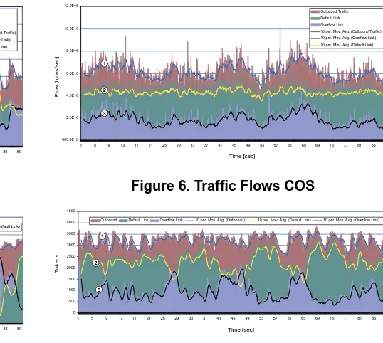
Figure 6. Traffic Flows COS
0 500 1000 1500 2000 2500 3000 3500 4000 4500
1 5 9 13 17 21 25 29 33 37 41 45 49 53 57 61 65 69 73 77 81 85 89 Outbound Default Link Overflow Link 10 per. Mov. Avg. (Outbound) 10 per. Mov. Avg. (Default Link) 10 per. Mov. Avg. (Overflow Link)
Time [sec]
Tokens
1
2
3
Figure 7. Token Numbers COS
increases and the traffic load returns to the target bandwidth with minimal fluctuations.
At approx. 11/17/21/26/44/52/61/86 seconds further ele-phant flows arrive, but these are routed on the overflow link. For the elephant flows at 35/70/78 seconds a behaviour can be observed that is similar to the first peak. In these in-stances, the flows are routed on the default link. A second observation stands out concerning this trace: The number of active flows on the default link is far less than the number of active flows on the overflow link. This indicates that many persistent large flows are routed on this link.
Figure 6 depicts the traffic flow and Figure 7 depicts the token number for the second trace. In this instance, the traf-fic bursts are not as severe and the overflow scheme is able to adjust to changes in due time. The traffic fluctuations around the target bandwidth on the default link (2) are min-imal.
6. Conclusions
This paper address cost efficient outbound traffic
rout-ing in ISP networks that use the BGP protocol. It
in-troduced an LP formulation and a corresponding overflow routing scheme. The LP outlined the theoretical solution and the overflow scheme gave a practical implementation. The scheme is a function that has to be located in BGP en-abled routers, however it requires no changes to the existing BGP protocol.
The benefits can be summarised as follows: Microflows are routed independently and in an overflow manner. Under normal operating conditions (no failures) flows are routed on the same interface for their entire duration. Such active flows are not reassigned. Existing flows are not affected by the arrival or departure of other flows, neither microflows that are routed on the default link nor microflows that are routed on the overflow link.
The operation was demonstrated by simulations that used packet trace data. The simulation showed that the abil-ity to adjust the traffic to the target bandwidth on default links is limited by the occurrence of large persistent flows - an expected result. Target bandwidth dimensioning has to take these bursts into account, as it is also required for static link dimensioning. If the size and number of elephant flows is limited, the scheme adapts better to the set target bandwidth.
Further work has to address how load fluctuations can be incorporated in the LP model and how the LP results can be used to fine tune the overflow scheme. Further more, an ex-tended overflow scheme can incorporate Quality of Service (QoS) information as well as address QoS routing issues and different traffic classes.
The main emphasis of this paper was on cost efficient routing, but overflow routing can be also motivated by other factors. The SAPOR scheme can be used for backup pur-poses or in failure scenarios, for load and performance man-agement. Future work has to address some of these issues and the possible implementation of the SAPOR scheme in edge routers.
7. Acknowledgements
The authors would like to thank the National Labora-tory for Applied Network Research (NLANR) for making their traffic traces publicly available to the research commu-nity. The financial assistance for this work by the Australian Telecommunications Cooperative Research Centre (ATcrc) also is gratefully acknowledged.
References
[1] L. Subramanian, S. Agarwal, J. Rexford, and R.H. Katz. Characterizing the internet hierarchy from
mul-tiple vantage points. In Proc. of IEEE INFOCOM
2002, New York, NY, Jun 2002.
[2] Y. Rekhter and T. Li. A Border Gateway Protocol 4 (BGP4). IETF, March 1995. RFC 1771.
[3] B. Quoitin, S. Uhlig, C. Pelsser, L. Swinnen, and O. Bonaventure. Interdomain traffic engineering with BGP. IEEE Communications Magazine, 41(5):122– 128, May 2003.
[4] I. Van Beijnum. BGP: Building Reliable Networks with the Border Gateway Protocol. O’Reilly, Septem-ber 2002.
[5] B. Quoitin, S. Uhlig, and O. Bonaventure. Using re-distribution communities for interdomain traffic engi-neering. In COST263 Workshop of Quality of future Internet Services, number 2511 in LNCS, 2002.
[6] S. Uhlig, O. Bonaventure, and B. Quoitin. Interdo-main traffic engineering with minimal BGP
config-urations. In Proc. of 18th International Teletraffic
Congress (ITC), Berlin, Germany, September 2003.
[7] G. R. Ash. Dynamic Routing in Telecommunication Networks. McGraw-Hill, 1997.
[8] A.A. Kist and R.J. Harris. Scheme for alternative
packet overflow routing (SAPOR). In Workshop
on High Performance Switching and Routing (HPSR 2003), Turin, Italy, June 2003.
[9] National Laboratory for Applied Network Research
(NLANR). NLANR network traffic packet header
traces, November 2003. http://pma.nlanr.net/Traces/.
[10] Cisco. BGP Best Path Selection Algorithm, November 2003. http://www.cisco.com/warp/public/459/25.pdf.
[11] Z. Cao, Z. Wang, and E. Zegura. Performance of
hashing-based schemes for internet load balancing. In Proc. of IEEE INFOCOM 2000, volume 1, pages 332 –341, 2000.