University of Southern Queensland
Faculty of Engineering & Surveying
Development of a Remote Laboratory System for
External University Students
A dissertation submitted by
A. Birkbeck
in fulfilment of the requirements of
ENG4112 Research Project
towards the degree of
Bachelor of Engineering (Computer Systems)
Abstract
This research project develops Remote Laboratory Software to allow students to per-form laboratory experiments from off campus. The software allows students to exter-nally use a Remote Laboratory, which is an experiment laboratory that is specially setup so students can operate it as if they were in the laboratory itself.
Three times a year external students travel to the University of Southern Queensland for their practical experiments at residential school. As external students often live, and hence have families and work commitments, in different cities or other states it is difficult for them to travel to the university campus at the required time. It was there-fore both practical and useful to develop a Remote Laboratory System that students use to do selected experiments from home, reducing the time they are required to be on campus.
Currently there are several Remote Laboratories in Australia, as a number of these sys-tems were experiencing difficulties, a new system designed specifically for the University of Southern Queenslandâs needs was a viable alternative.
University of Southern Queensland
Faculty of Engineering and Surveying
ENG4111/2 Research Project
Limitations of Use
The Council of the University of Southern Queensland, its Faculty of Engineering and Surveying, and the staff of the University of Southern Queensland, do not accept any responsibility for the truth, accuracy or completeness of material contained within or associated with this dissertation.
Persons using all or any part of this material do so at their own risk, and not at the risk of the Council of the University of Southern Queensland, its Faculty of Engineering and Surveying or the staff of the University of Southern Queensland.
This dissertation reports an educational exercise and has no purpose or validity beyond this exercise. The sole purpose of the course pair entitled âResearch Projectâ is to contribute to the overall education within the studentâs chosen degree program. This document, the associated hardware, software, drawings, and other material set out in the associated appendices should not be used for any other purpose: if they are so used, it is entirely at the risk of the user.
Prof F Bullen
Dean
Certification of Dissertation
I certify that the ideas, designs and experimental work, results, analyses and conclusions set out in this dissertation are entirely my own effort, except where otherwise indicated and acknowledged.
I further certify that the work is original and has not been previously submitted for assessment in any other course or institution, except where specifically stated.
A. Birkbeck
0050007144
Signature
Acknowledgments
Thanks to Steve Murray at The University of Technology, Sydney, Lachlan Webb at University of Wollongong, Clive Ferguson at Deakin University, Euan Lindsay from Curtin University, and James Trevelyan from University of Western Australia for shar-ing their knowledge and information about the remote laboratories that they had deal-ings with.
Thanks to USQ lectures for providing me with practical course books which provided information about what experiments are currently being run at USQ.
Thanks to John Leis for being my voice, arms, and legs in Toowoomba for information gathering and for the numerous consultations and assistance he offered throughout the year. Lastly thank you to Merridee McKay who has been a guinea pig for my ideas, and designs, and had the distasteful pleasure of proof reading my first draft.
Thank you!
A. Birkbeck
Contents
Abstract i
Acknowledgments iv
List of Figures xii
List of Tables xiii
Glossary xv
Chapter 1 Introduction 1
1.1 What is a Remote Laboratory? . . . 1
1.2 Objectives . . . 1
1.3 Implementation . . . 2
1.4 Consequential Effects . . . 2
1.5 Methodology . . . 5
1.6 Risk Assessment . . . 8
CONTENTS vi
1.6.2 Beyond the completion of the project . . . 9
1.7 Resources Required . . . 10
1.8 Background Research . . . 11
1.9 Practical Courses . . . 14
1.10 Proof of Completion . . . 19
Chapter 2 Interface and Host Program Configuration Alternatives 20 2.1 Interface Program Connections . . . 21
2.1.1 Web Browser . . . 21
2.1.2 Remote Desktop Connection Based . . . 21
2.1.3 VPN Based . . . 22
2.1.4 HTTP Tunneling . . . 22
2.1.5 Conclusion . . . 23
2.2 Interface Program . . . 24
2.2.1 Website . . . 24
2.2.2 Client Program Based . . . 24
2.2.3 Conclusion . . . 25
Chapter 3 Hardware Requirement Alternatives 26 3.1 Laboratory Equipment Interface Method . . . 26
CONTENTS vii
3.1.2 Robotic Arm . . . 27
3.1.3 Digital Switch . . . 28
3.1.4 Conclusion . . . 29
3.2 Computer Interface Method . . . 30
3.2.1 USB . . . 30
3.2.2 FireWire/IEEE-1394 . . . 30
3.2.3 Serial Port . . . 31
3.2.4 Parallel Port . . . 31
3.2.5 Conclusion . . . 32
3.3 Switches . . . 33
3.3.1 USB Relay Alternatives . . . 33
3.3.2 Conclusion . . . 35
3.4 User Feedback . . . 36
3.4.1 Video . . . 36
3.4.2 Still Images . . . 36
3.4.3 Audio . . . 37
3.4.4 Software physical event . . . 37
3.4.5 Software event . . . 37
3.4.6 Conclusion . . . 38
CONTENTS viii
4.1 Information Storage . . . 39
4.1.1 Domain . . . 39
4.1.2 Existing database . . . 40
4.1.3 Microsoft Access database . . . 40
4.1.4 MSDE database . . . 41
4.1.5 MySQL . . . 41
4.1.6 SQL Server database . . . 42
4.1.7 Oracle database . . . 42
4.1.8 Textfile . . . 43
4.1.9 Written into the code of the program . . . 43
4.1.10 Conclusion . . . 43
4.2 Booking System . . . 45
4.2.1 Single User System . . . 45
4.2.2 User, Viewer System . . . 45
4.2.3 Multi-User System . . . 46
4.2.4 Conclusion . . . 47
4.3 Programming Languages . . . 48
4.3.1 ASP . . . 48
4.3.2 ASP.Net . . . 48
CONTENTS ix
4.3.4 ColdFusion . . . 49
4.3.5 Java . . . 49
4.3.6 PHP . . . 50
4.3.7 Visual Basic . . . 50
4.3.8 Conclusion . . . 51
Chapter 5 Required System Specification 52 5.1 Assumptions . . . 52
5.2 Software Operation . . . 54
5.3 Interface Program Operation . . . 55
5.4 Host Program Operation . . . 57
5.5 Database Structure . . . 58
5.5.1 Membership and Role Provider Tables . . . 59
5.5.2 Experiment Table . . . 62
5.5.3 User Grouping . . . 62
5.5.4 Subject Grouping . . . 64
5.5.5 Experiment Period Table . . . 65
5.5.6 Instructions Table . . . 65
5.5.7 Switches Table . . . 66
5.5.8 Booking Table . . . 67
CONTENTS x
Chapter 6 Conclusion 69
6.1 Limitations . . . 71
6.2 Future Work . . . 72
References 73 Appendix A Project Specification 78 Appendix B MySQL Database Code 80 Appendix C Interface Program Code 86 C.1 Index.ASPX . . . 87
C.2 Index.ASPX.VB . . . 87
C.3 Login.ASPX . . . 88
C.4 Login.ASPX.VB . . . 89
C.5 Passwordrecovery.ASPX . . . 90
C.6 Passwordrecovery.ASPX.VB . . . 91
C.7 Mainmenu.ASPX . . . 91
C.8 Mainmenu.ASPX.VB . . . 94
C.9 Changepassword.ASPX . . . 95
C.10 Changepassword.ASPX.VB . . . 96
C.11 Editgroup.ASPX . . . 96
CONTENTS xi
C.13 Editsubjects.ASPX . . . 103
C.14 Editsubjects.ASPX.VB . . . 107
C.15 Editusers.ASPX . . . 110
C.16 Editusers.ASPX.VB . . . 119
C.17 Edituserssubjects.ASPX . . . 123
C.18 Edituserssubjects.ASPX.VB . . . 125
C.19 Default.css . . . 127
List of Figures
List of Tables
1.1 Current Remote Laboratories . . . 13
1.2 Engineering Practical Courses Offered by USQ . . . 15
1.3 Engineering Practical Courses Offered by USQ . . . 16
1.4 Engineering Practical Courses Offered by USQ . . . 17
1.5 Engineering Practical Courses Offered by USQ . . . 18
2.1 System Configuration Methods Summary . . . 25
3.1 Laboratory Interface Methods Summary . . . 29
3.2 Computer Interface Methods Summary . . . 32
3.3 Relay Manufacturers . . . 33
3.4 Relay Specifications . . . 34
3.5 USB Relay Alternative Summary . . . 35
3.6 Feedback Methods Summary . . . 38
LIST OF TABLES xiv
4.2 Booking Systems Summary . . . 47
4.3 Programming Languages Summary . . . 51
5.1 mysql roles table . . . 60
5.2 mysql usersinroles table . . . 60
5.3 mysql membership table . . . 61
5.4 experiments table . . . 62
5.5 groups table . . . 63
5.6 groupusers table . . . 63
5.7 subjects table . . . 64
5.8 usersinsubjects table . . . 64
5.9 experimentperiod table . . . 65
5.10 instructions table . . . 65
5.11 switches table . . . 66
5.12 booking table . . . 67
Glossary
Client computer is the computer that is used by the remote user to access the lab-oratory.
Host Computer is a program that is to control the laboratory equipment.
RLS Remote Laboratory Software
Web Server is a computer that hosts the software that the remote user will interact with.
USQ is the University of Southern Queensland.
Chapter 1
Introduction
1.1
What is a Remote Laboratory?
For the purposes of this research project a Remote Laboratory is an experiment lab-oratory that is specially setup so that lablab-oratory technicians can operate it as if they were in the laboratory itself. Using a computer the technician interacts with a Remote Laboratory Program that sends information via the Internet to the Remote Labora-tory where the instructions are executed by robotics in the previously set up laboraLabora-tory. This improves the safety and convenience of performing an experiment by allowing it to be performed from the next room or even across the world.
1.2
Objectives
1.3 Implementation 2
1.3
Implementation
External students are required to attend residential school at the University of South-ern Queensland numerous times throughout there studies where laboratory experiments are performed for various subjects. Although attending residential school exposes stu-dents to a wide variety of equipment, methods, and experiences that are essential for their education there are many possible experiments offered in the practical courses at the University of Southern Queensland that have the potential be run as a remote laboratory experiment. By implementing selected experiments as remote laboratories students will be able to obtain the understanding that they would normally gain from attending residential school without attending the university, which would save them both time and money.
1.4
Consequential Effects
While developing the remote laboratory software many aspects of sustainability, safety and ethics were considered.
⢠The set up required for the remote laboratory system will not undermine the
1.4 Consequential Effects 3
⢠The development of this project does not influence environmental protection
is-sues (Towards Sustainable Engineering Practice: Engineering Frameworks for Sustainability 1997) as it is software that is being developed, and as such has no immediate or long term effects on the environment. Once the system is run-ning there will be a minute influence in power consumption by the runrun-ning of computers to operate the software, but not enough to notably effect the environ-ment. Also, as previously mentioned, if additional lines are required environments may be varied with the development of these lines.
Alternatively there are positive environmental side effects from the development of this software. As the system is accessed remotely people no longer need to commute to the laboratory site, therefore would create less vehicle pollution.
⢠Possible global environmental impacts (Towards Sustainable Engineering
Prac-tice: Engineering Frameworks for Sustainability 1997) are very minimal. Long term electricity sources will be required, so for optimal environmental preservation the ideal system is a renewable energy source (i.e. hydro, wind or solar power). Should the system become vastly used then high capacity communication lines will be required. This will not impact the environment or future development as existing phone lines will simply be replace by fibre-optic ones.
⢠The only aspect of this projects implementation that could cause environmental
degradation (Towards Sustainable Engineering Practice: Engineering Frameworks for Sustainability1997) is the long-term side effects of energy consumption, which is currently being researched by scientists around the world.
⢠The participation of any concerned citizens (Towards Sustainable Engineering
Practice: Engineering Frameworks for Sustainability 1997) would be necessary with the implementation of this project only in cases were additional communi-cation lines are required. In these cases any concerned parties (i.e. land owners, conservationists, and developers) would be involved in discussion with the council before lines were constructed.
⢠Pollution will not be created by the implementation of this project; it stands to
1.4 Consequential Effects 4
⢠The remote laboratory system will be equally accessible to all groups of
peo-ple whether majority and minority (Towards Sustainable Engineering Practice: Engineering Frameworks for Sustainability1997); the only requirement is a com-puter and access to the Internet. People in a low socioeconomic group who cannot purchase these requirements would access them elsewhere (local library or univer-sity), which they would already be necessary for other aspects of their university studies.
Possible effects on employment are: there will be less demand of Toowoomba resources (accommodation, tourism, and retailers) as less people would be com-muting there yearly. To offset that more employment opportunities would exist in the construction, installation, and maintenance of the system. While employ-ment opportunities still exist the necessary qualifications vary significantly from the previous employment market to the new job fields. Further education or training may be required by job seekers but they would be rewarded by entering a higher paying job field.
⢠The remote laboratory software will not be used in under developed countries
(Towards Sustainable Engineering Practice: Engineering Frameworks for Sustainability 1997) as the software is being developed for university laboratory experiment pur-poses. There will be no effect for countries accessing the university, as no labour is increased or decreased in that country if students travel to the USQ campus or access the system remotely.
⢠This project development could be used for global sustainability and international
1.5 Methodology 5
1.5
Methodology
1. Research current remote laboratories to discover the basic structure of how a re-mote laboratory works.
This research will be performed by reading reference material and by contacting the administrators of several remote laboratories located within Australia and requesting any documentation or manuals explaining how the software operates. This may also include visiting current sites if this can be arranged.
2. Investigate how other programmers have developed their software.
If possible gain access to operating remote laboratories, source code used to oper-ate the laboratory equipment or, alternatively, download a copy of the programs used, and explore their operation and features.
3. Identify flaws associated with currently used methods.
Through current program exploration an understanding of how the program op-erates will be gained. Then the programs strengths and weaknesses can be iden-tified.
4. Research the software and hardware available at USQ and other potential con-sumers.
Through investigation of the current market for remote laboratories it is possible to determine the likely clients and through contact with the IT department of the clients, it is possible to determine how their system is currently running.
5. Identify which platform the system will run on.
A platform, in which the system will operate on, will be decided based on the above points mentioned; Current software, flaws in current software, and clientsâ software and hardware.
6. Determine any additional hardware required for the remote laboratory.
1.5 Methodology 6
7. Evaluate hardware requirements and recommend a vendor.
Tabulate the advantages and disadvantages of each of the hardware manufactures and weigh these options up will determine the best hardware manufacturer(s) for the tasks.
8. Research alternative methods for the tasks required to implement the remote lab-oratory software.
By consulting current journals and utilising current technology a list of alternative to each task can be created.
9. Evaluate the alternative methods of performing those tasks.
Each alternative method will tabulated showing the positive and negative effects of each method to determine the best alternative solution to the current method of performing a task.
10. Assess programming languages to determine which best implements the remote laboratory, and can operate on the hardware and software used by the consumers. Each alternative method can be tabulated with higher weights given to important features, and lower weights given to less important features so to determine the best alternative solution to the current method of performing a task.
11. Develop a prototype of the remote laboratory software.
Code the software for the remote laboratory by completing the tasks required using the methods decided on.
12. Extensively test the system to determine flaws.
Setup several test experiments and perform them as they would be performed by a remote user. Perform operations that wouldnât normally occur in an effort to try to break the system. If a flaw is found correct it.
13. Gain user feedback on the operation of the system.
1.5 Methodology 7
1.6 Risk Assessment 8
1.6
Risk Assessment
1.6.1 During execution of the project
⢠In the designing stage of this project the first risk could be incorrectly
program-ming the equipment. The exposure to this risk is very rare (only once during the programming stage) and the likelihood of it occurring is slight. If programmed incorrectly the consequences would be damage incurred to equipment. This risk is avoidable with careful attention being given while programming. In the event of occurrence new equipment would need to be purchased.
⢠During the setup of a laboratory experiment a risk of electrocution exists. The
likelihood is significant but the exposure will vary depending on how many differ-ent experimdiffer-ents are used. Consequences may vary from minor injury to possible death. The electrical power source hazard is unavoidable as it is necessary for the experiment but the risk can be drastically minimised by checking all equipment for faults before using, turning the power source off while connecting, and con-firming circuit is wired correctly. Also in case of emergencies a fire extinguisher should be easily accessible.
Minor and major damage could also occur to equipment if this incident occurred and the same prevention steps as above would need to be taken.
⢠Once the equipment is connected and running there is the risk of a short circuit in
1.6 Risk Assessment 9
⢠When software system is operating on the Internet or accessible to the public
there exists a risk that the system will be hacked into and manipulated in ways in which the software was not designed to operated. The likelihood of such an event occurring varies depending on the nature of the users who operate the system and number of people who access the system. The risk can be reduced by locating the software on a secure server and programming in several safeguards that stop the system from operating should an attack be detected. The consequences from the system being hacked vary from an unauthorised access to damage to equipment or the Remote Laboratory Software.
⢠While users are operating the software they will be working on a computer
fquently for numerous hours (times will vary depending on the experiment re-quirements) so they could stand a chance of getting eye fatigue from looking at the monitor, or repetitive strain injury (RSI) from using the mouse, keyboard or sitting at a desk. The likelihood of either of these occurring is very slight but precautionary measures can be taken to minimise the risk even further. Practi-cals could be designed to only go for short periods of time allowing the user to have a break between experiments. Users could also be prompted with designed short movement activities (away from the computer desk) to be completed at appropriate intervals during the experiment process to give them a break.
1.6.2 Beyond the completion of the project
⢠If the remote laboratory software is destroyed at the completion of this project
no adverse effects will occur to the environment or society.
⢠If the project is taken onboard and used by the university all the previously
1.7 Resources Required 10
1.7
Resources Required
The development Remote Laboratory Software requires access to a computer which will be used to code and test the software. Development also requires the appropriate programming language tools, such as compilers and linkers in order to implement a solution. During the development stage a laboratory interface device will also be needed to test the software and, if required, a program that is used to run the website. A feedback device is also needed to ensure that the user can understand what has occurred in the remote laboratory.
1.8 Background Research 11
1.8
Background Research
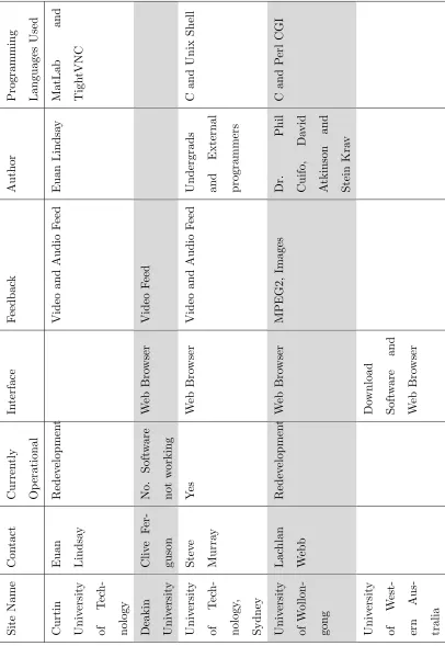
Currently there are many Remote Laboratories in Australia, several of which are used for educational purposes. Table 1.1 shows several Universities in Australia that have remote laboratories and how they are operating.
It was determined that the majority of these laboratories operated in a method that, for the purpose of this project, will called the âinterface and host methodâ. This method operates by:
⢠The client computer interacts with an interface programs which allows the users
to change parts of the experiment. This is often a website or customised software that is developed specifically for a particular experiment.
⢠The interface program then communicates these changes with a host program by
using a log file which then interprets these instructions and operates the machin-ery or circuitry to perform the requested actions.
⢠The feedback of the actions performed in the laboratory are then streamed back
to the interface program which displays this to the user.
Predominately these remote laboratories were written in Java for the web interface, and are written in portable programming languages such as C and C++ for the host program. They generally provide video and audio feedback to the user so that they can easily understand what is occurring.
1.8 Background Research 12
1.8 Background Research 13 S it e N am e C on ta ct C u rr en tl y O p er at io n al In te rf ac e F ee d b ac k A u th or P ro gr am m in g L an gu ag es U se d C u rt in U n iv er si ty of T ec h -n ol og y E u an L in d sa y R ed ev el op m en t V id eo an d A u d io F ee d E u an L in d sa y M at L ab an d T ig h tV N C D ea k in U n iv er si ty C li ve F er -gu so n N o. S of tw ar e n ot w or k in g W eb B ro w se r V id eo F ee d U n iv er si ty of T ec h -n ol og y, S y d n ey S te ve M u rr ay Y es W eb B ro w se r V id eo an d A u d io F ee d U n d er gr ad s an d E x te rn al p ro gr am m er s C an d U n ix S h el l U n iv er si ty of W ol lo n -go n g L ac h la n W eb b R ed ev el op m en t W eb B ro w se r M P E G 2, Im ag es D r. P h il C u if o, D av id A tk in so n an d S te in K ra v C an d P er l C G I U n iv er si ty of W es t-er n A u s-tr al ia D ow n lo ad S of tw ar e an d W eb B ro w se r
1.9 Practical Courses 14
1.9
Practical Courses
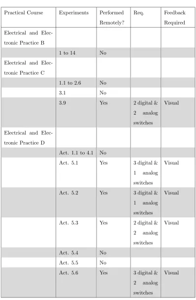
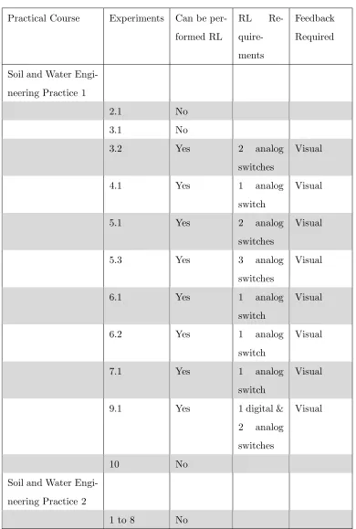
Currently there are several practical courses running in the engineering department of the University of Southern Queensland. Tables 1.2 to 1.5 show a list of several practice courses offered by USQ, the experiments that are performed in that course, and whether the experiment can be performed remotely.
The information interpreted in these tables was sourced from the practical books of; Civil Materials Practice, Computer Systems Engineering Practice, Field Practice, Mechatronic Practice 1, Professional Practice 1, Professional Practice 2, Electrical and Electronic Practice A, Electrical and Electronic Practice B, Electrical and Electronic Practice C, Electrical and Electronic Practice D, Soil and Water Engineering Practice 1, and Soil and Water Engineering Practice 2.
Experiments have been classified as not able to be performed remotely if:
⢠The experiment only required watching a seminar or video, which would be best
achieved with the students watching a live video feed.
⢠The experiment would best work with a remote desktop connection. In these
situations this experience can be obtained by allowing students to connect directly to university computers in which the software package is installed.
⢠The activities are too difficult to perform remotely because of the actions
re-quired; I.E. extensive equipment set up, configuring time, and possibilities of voiding warranty. For example, many experiments involve the use of a Cathode Ray Oscilloscope. To operate an oscilloscope remotely would require a large num-ber of connections interfacing with the oscilloscope and these connections would possibly void the devices warranty. A better alternative is to operate a PC-based oscilloscope via a remote desktop connection.
1.9 Practical Courses 15
Practical Course Experiments Performed Remotely?
Req. Feedback Required
Civil Materials Prac-tice
Aggregate No
Concrete No
Timber No
Bitumen, Asphalt, and Skid
Resistance No
Soil No
Traffic Study No Road Maintenance Needs Assessment
Study No
Computer Systems Engineering Practice
1.1 to 2.6 No
Field Practice
Oral
Presentation No
Report No
Mechatronic Prac-tice 1
Parts 1 to 6 No Professional Practice
1
None
Professional Practice 2
None
1.9 Practical Courses 16
Practical Course Experiments Performed Remotely?
Req. Feedback Required Electrical and
Elec-tronic Practice A
1 No
2, 3 & 4 Yes 4 digital switches
Visual
5 & 6 No
7 & 8 Yes 2 digital
switches
Visual
9 No
Act. 5.2 to 5.6 No
A1 No
A2 & A3 Yes 1 digital & 2 analog switches
Visual
B1 & B2 Yes 2 digital & 1 analog switches
Visual
C1 Yes 1 digital Visual
C2 No
C3 Yes 3 digital &
1 analog switches
Visual
D1 Yes 1 digital Visual
D2 Yes 3 digital &
4 analog switches
Visual
1.9 Practical Courses 17
Practical Course Experiments Performed Remotely?
Req. Feedback Required Electrical and
Elec-tronic Practice B
1 to 14 No
Electrical and Elec-tronic Practice C
1.1 to 2.6 No
3.1 No
3.9 Yes 2 digital &
2 analog switches
Visual
Electrical and Elec-tronic Practice D
Act. 1.1 to 4.1 No
Act. 5.1 Yes 3 digital & 1 analog switches
Visual
Act. 5.2 Yes 3 digital & 1 analog switches
Visual
Act. 5.3 Yes 2 digital & 2 analog switches
Visual
Act. 5.4 No
Act. 5.5 No
Act. 5.6 Yes 3 digital & 2 analog switches
[image:33.595.121.519.108.718.2]Visual
1.9 Practical Courses 18
Practical Course Experiments Can be per-formed RL
RL Re- quire-ments
Feedback Required
Soil and Water Engi-neering Practice 1
2.1 No
3.1 No
3.2 Yes 2 analog
switches
Visual
4.1 Yes 1 analog
switch
Visual
5.1 Yes 2 analog
switches
Visual
5.3 Yes 3 analog
switches
Visual
6.1 Yes 1 analog
switch
Visual
6.2 Yes 1 analog
switch
Visual
7.1 Yes 1 analog
switch
Visual
9.1 Yes 1 digital &
2 analog switches
Visual
10 No
Soil and Water Engi-neering Practice 2
[image:34.595.126.516.124.703.2]1 to 8 No
1.10 Proof of Completion 19
1.10
Proof of Completion
In order for the Remote Laboratory to become an integral part of the practical courses the experiments which are performed remotely need to provide adequate proof of stu-dent completion to the course examiner. Currently stustu-dents attend resistu-dential school and perform experiments in the presence of a USQ staff member who signed off on an experiment once they have witnessed the student performing it. With the experiment being performed remotely in a laboratory students are not being overseen constantly and, as such, the need arises for evidence that the student has completed the experi-ment. Evidence of studentsâ successful completion of experiments can be gathered in several different ways.
As with the current method a USQ staff member could be present in the remote labo-ratory to ensure that all current experiments are being completed correctly. Students would log into the system and perform the experiments and the supervising staff would sign them off once the experiment was completed correctly. This staff member would also need to be able to communicate with the student completing the experiment so that they could inform them of anything that was being performed incorrectly.
Alternatively a software solution could be implemented in which students are required to take screen shots at important milestones in the experiment. These screen shots are to be submitted along with any calculations to the examiner as proof that the student has completed the experiment as required by the practice course.
Chapter 2
Interface and Host Program
Configuration Alternatives
Using the information gained in the background research it was established that the âinterface and hostâ method was the best approach for the purposes of this project. This interface and host method involves two programs that operate independently to complete the remote laboratory.
The host program is primarily responsible for periodically checking the log (created by the interface program), verifying the instructions, and implementing the requested actions. The host program would also be responsible for preparing the feedback of the experiment so that the website may portray the feedback to the user.
2.1 Interface Program Connections 21
The cost of implementing the interface and host program based solution depends on the programming language that the site is to be written in, and whether it is being hosted locally at the university, or remotely by an external provider.
2.1
Interface Program Connections
In the interface and host method, users are required to interact with the interface program in order to be able to access the remote laboratory. There are several ways in which the user can interact with the interface program.
2.1.1 Web Browser
This alternative allows the users of the remote laboratory to use any recent web browser to access the remote laboratory. This has the advantage of not requiring specialised software to be installed in order to access the remote laboratory which is beneficial for those users who are trying to access the laboratory from a restricted network where software cannot be installed.
2.1.2 Remote Desktop Connection Based
2.1 Interface Program Connections 22
2.1.3 VPN Based
The user could use a VPN connection to connect to the university network. This would enable them to access the interface program without occupying any university computers. The VPN based method provides greater network security then using a remote desktop connection as no additional external ports would need to be opened if a VPN pass through router was used. This method however would also allow potential hackers access to the university network should they be able to connect via VPN. VPN is freely available on Mac, Windows, and Linux platforms (Using a Linux L2TP/IPsec VPN server with Mac OS X2007).
2.1.4 HTTP Tunneling
2.1 Interface Program Connections 23
2.1.5 Conclusion
2.2 Interface Program 24
2.2
Interface Program
The interface program is the program that the user interacts with in order to make changes in the remote laboratory. The interface program may be created in two different methods.
2.2.1 Website
The website based solution could be configured using or not using the host computer as the web server. If the host computer is the web server then the system gains the benefits of less computers required to run the software and thus less cost. If the host computer is not the web server then the system benefits by not requiring a web server to be located on campus. The web server can then be hosted by a specific provider which reduces the computer requirements at the university in order to run the system.
2.2.2 Client Program Based
2.2 Interface Program 25
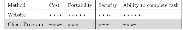
2.2.3 Conclusion
Method Cost Portability Security Ability to complete task Website ? ? ?? ? ? ? ? ? ? ? ?? ? ? ? ? ?
[image:41.595.126.507.136.200.2]Client Program ? ? ?? ? ? ? ? ? ? ? ? ??
Table 2.1: System Configuration Methods Summary
Chapter 3
Hardware Requirement
Alternatives
3.1
Laboratory Equipment Interface Method
The system will need to be able to interface with the equipment in the laboratory in such a way that experiment parameters may be changed by the user.
3.1.1 Analog Switches
3.1 Laboratory Equipment Interface Method 27
3.1.2 Robotic Arm
A robotic arm provides a more hands on approach to the experiments. The user would be in direct control of the operation of a robotic arm in which they can make changes as if they were doing it in person.
When using a robotic arm to control an experiment a new laboratory experiment can be setup easily simply placing all the equipment within the reach of the robotic are which the user has control of. The user can then more the equipment into position to yield the desired result from the experiment.
In order to accurately control the operation of the robotic arm the user must receive real-time feedback. Any delay in the feedback system would cause the system to be difficult to use. The robotic arm would make the experiment more prone to short circuits. The arm would need to be insulated so as to not short circuit the experiment. Secondly, this increase the chances that the user will connect a conductor incorrectly causing damage to the circuit and in more extreme circumstances, the building wiring.
3.1 Laboratory Equipment Interface Method 28
3.1.3 Digital Switch
A digital switch provides the users with the ability to turn on and off a circuit. A digital switch can be easily connected directly to many different applications making this alternative very flexibly. Digital switches can be implemented by relays, Phototransistor Optocouplers, and transistors.
A relay is a small electronic device that uses magnetism to connect or disconnect two internal terminals in the relay. These two terminals connect to external circuitry allowing the relay to control whether the circuit is open or closed. Relays operate on different voltages, typically ranging from 300 to 600 volts AC with the electromagnet operating on voltages ranging from 24 to 120 volts AC. Relays also come is several different configurations including single pole single throw, double pole single throw, single pole double throw, double pole double throw, and quadruple pole double throw (Relay - Wikipedia 2007). Due to these features offered by relays they are a flexibility method of implementing a digital switch.
A transistor is a small current controlled semiconductive device that is used to am-plify an electric current or as an electronic switch. The transistor works by applying a base/emitter voltage which increases the base/emitter current which allows for an exponential increase of the collector/emitter current (Transistor - Wikipedia 2007).
3.1 Laboratory Equipment Interface Method 29
3.1.4 Conclusion
Method Flexibility Cost Ability to complete task Safety
Robotic Arm ? ? ? ? ? ? ? ? ?? ? ? ?
Digital Switch ? ? ?? ? ? ? ? ? ? ? ? ? ? ??
[image:45.595.127.505.134.218.2]Analog Switches ? ? ?? ? ? ? ? ? ? ? ?? ? ? ??
Table 3.1: Laboratory Interface Methods Summary
The robotic arm provides the user with the most flexibly means in which to manipulate the experiment and the fastest setup of new experiments. Unfortunately it is too expensive to implement for this research project and as such will no longer be considered a viable option.
3.2 Computer Interface Method 30
3.2
Computer Interface Method
The Laboratory Equipment interface will need to be connected to a computer in order for it to work correctly. This can be done in several ways.
3.2.1 USB
USB stands for Universal Serial Bus. USB 1.1 and is capable of transferring up to 12Mpbs. A singular USB port can have up to 127 devices connected to it and is hot swappable. USB 2.0 is capable of transferring up to 480Mbps (USB 2007). USB 2.0 devices are backwards compatible with USB 1.1, meaning a USB 2.0 device can be connected to a USB 1.1 computer and a USB 1.1 device can be connected to a USB 2.0 computer. Currently all new Asus and Gigabyte motherboards are equipt with at lease 2 USB ports which are normally built directly onto the motherboard itself so that devices may be connected directly to the back panel (Asus Motherboard2007) (Gigabyte Motherboard2007).
3.2.2 FireWire/IEEE-1394
3.2 Computer Interface Method 31
3.2.3 Serial Port
Serial ports are capable of data transfer speeds of up to 20kbps (Axelson 2005). Serial ports are equipt on most new Gigabyte boards however the new Asus motherboards no longer have a serial port build onto the motherboard (Asus Motherboard 2007) (Gigabyte Motherboard 2007). In instances such as this a PCI, PCMCIA or USB to Serial adapter card needs to be purchased to interface with the serial device.
3.2.4 Parallel Port
3.2 Computer Interface Method 32
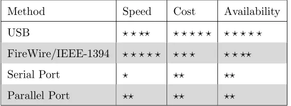
3.2.5 Conclusion
Method Speed Cost Availability
USB ? ? ?? ? ? ? ? ? ? ? ? ? ? FireWire/IEEE-1394 ? ? ? ? ? ? ? ? ? ? ??
Serial Port ? ?? ??
[image:48.595.180.463.136.239.2]Parallel Port ?? ?? ??
Table 3.2: Computer Interface Methods Summary
All of these computer interface methods can easily be acquired via the purchase of an add-on card should the computer not have the required functionality. Although doing so increases overall cost of the system. Interface methods such as USB and FireWire appear to be replacing serial and parallel with the release of USB printers and scanners, and the removal of these ports from some manufacturers motherboards.
3.3 Switches 33
3.3
Switches
In order for the Remote Laboratory to be able to operate all of the possible experiments from Tables 1.2 to 1.5 the Remote Laboratory needs to provide 4 digital and 4 analog switches.
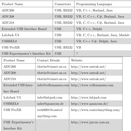
3.3.1 USB Relay Alternatives
Product Name Connectors Programming Languages
ADU200 USB, RS232 VB, C++, Borland, Java
ADU208 USB, RS232 VB, C, C++, C#, Borland, Java
ADU218 USB, RS232 VB, C, C++, C#, Borland, Java
Extended USB Interface Board USB VB, C++, Delphi
LabJack U3 USB VB, C, C++, Borland, Java, Matlab
USBREL8 USB VB, C++ C#, Delphi, Java
USB ProXR USB, RS232 VB
USB Experimenterâs Interface Kit USB ?
Product Name Contact Details Website
ADU200 [email protected] http://www.ontrak.net/ ADU208 [email protected] http://www.ontrak.net/ ADU218 [email protected] http://www.ontrak.net/ Extended USB
Inter-face Board
[email protected] http://www.vellemanusa.com
LabJack U3 [email protected] http://www.labjack.com USBREL8 [email protected] http://www.quancom.de/ USB ProXR tech0001@control
anything.com
http://www.controlanything.com/
USB Experimenterâs Interface Kit
[image:49.595.115.548.272.703.2]http://www.jaycar.com.au
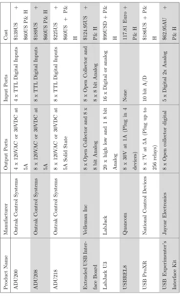
3.3 Switches 34 P ro d u ct N am e M an u fa ct u re r O u tp u t P or ts In p u t P or ts C os t A D U 20 0 O n tr ak C on tr ol S y st em s 4 x 12 0V A C or 30 V D C at 5A 4 x T T L D ig it al In p u ts $1 39 U S + $6 0U S P & H A D U 20 8 O n tr ak C on tr ol S y st em s 8 x 12 0V A C or 30 V D C at 5A 8 x T T L D ig it al In p u ts $1 89 U S + $6 0U S P & H A D U 21 8 O n tr ak C on tr ol S y st em s 8 x 12 0V A C or 30 V D C at 5A S ol id S ta te 8 x T T L D ig it al In p u ts $2 25 U S + $6 0U S + P & H E x te n d ed U S B In te r-fa ce B oa rd V el le m an In c 8 x O p en C ol le ct or an d 8 x 8 b it A n al og 8 x O p en C ol le ct or an d 8 x 8 b it A n al og $1 24 .9 5U S + P & H L ab J ac k U 3 L ab J ac k 20 x h ig h lo w an d 1 8 b it A n al og 16 x D ig it al or an al og $9 9U S D + P & H U S B R E L 8 Q u an co m 8 x 30 V at 1A (P lu g in 4 d ev ic es ) N on e 11 7. 81 E u ro + P & H U S B P ro X R N at io n al C on tr ol D ev ic es 8 x ?V at 5A (P lu g u p to 25 6 re la y s) 10 b it A /D $1 86 U S + P & H U S B E x p er im en te râ s In te rf ac e K it J ay ca r E le ct ro n ic s 8 x O p en co ll ec to r d ig it al 5 x D ig it al 2x A n al og $6 2. 95 A U + P & H
3.3 Switches 35
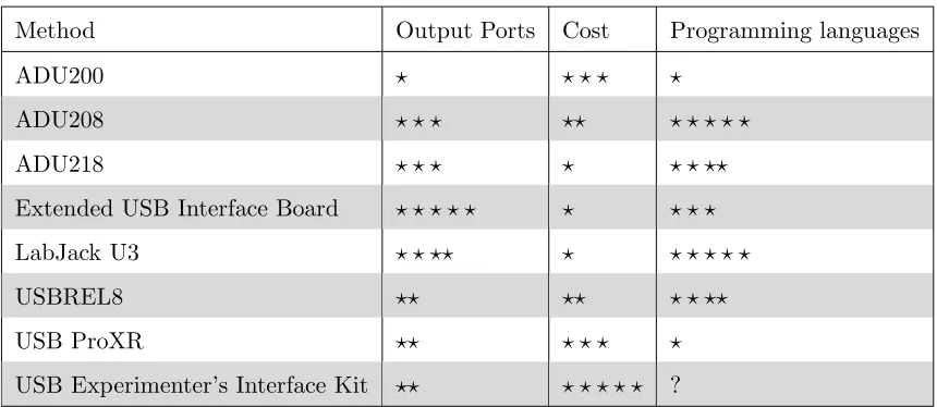
3.3.2 Conclusion
Method Output Ports Cost Programming languages
ADU200 ? ? ? ? ?
ADU208 ? ? ? ?? ? ? ? ? ?
ADU218 ? ? ? ? ? ? ??
Extended USB Interface Board ? ? ? ? ? ? ? ? ?
LabJack U3 ? ? ?? ? ? ? ? ? ?
USBREL8 ?? ?? ? ? ??
USB ProXR ?? ? ? ? ?
[image:51.595.114.544.134.321.2]USB Experimenterâs Interface Kit ?? ? ? ? ? ? ?
Table 3.5: USB Relay Alternative Summary
3.4 User Feedback 36
3.4
User Feedback
The user will need to be provided with some level of feedback to show them how the experiment reacted to the instructions issued.
3.4.1 Video
Video feedback provides the most detailed method of portraying to the user what oc-curs in the laboratory. Windows Media Encoder is freely available for download from Microsoftâs homepage and offers an easy implementation of both audio and video feed-back. Through trials of running this program the bandwidth required to transmit a video and audio signal ranges from 2000 kbps to 12 kbps depending on video size, qual-ity, and frames per second and the audio qualqual-ity, and number of audio channels. Video and audio streaming does however require some encoding and decoded and from expe-rience with these programs it was reveled that there is a delay in the video feed, usually of about 10 seconds. A delay of this magnitude can make performing experiments very difficult and slow especially when a particular event occurs very quickly.
3.4.2 Still Images
3.4 User Feedback 37
3.4.3 Audio
Audio feedback can be useful in conveying to the user what occurred during the ex-periment. Deakin University in Melbourne currently has a manufacturing laboratory which is controlled remotely. They provide audio and visual feedback to their students so that they can hear the noises that the machine makes when it cuts the material (Wong, Ferguson, Florance, Bantwal & Jones 2007). Unfortunately audio streaming is also subject to the delays incurred in video streaming.
3.4.4 Software physical event
The experiment could be designed so that when an special event occurs in the laboratory a signal is received by the host computer. When this signal is received by the host computer it triggers an event to be displayed to the user, such as a saved image, playback of a sound, or any other event that the user could identify.
3.4.5 Software event
3.4 User Feedback 38
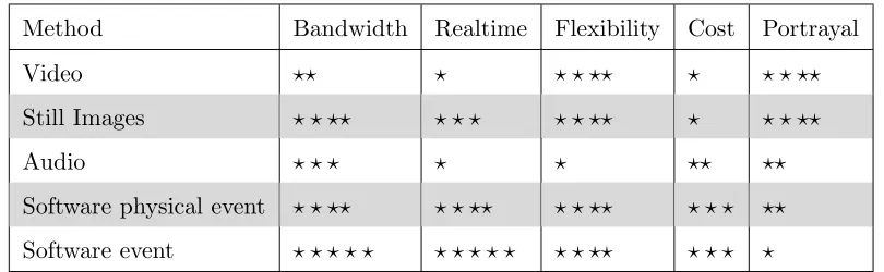
3.4.6 Conclusion
Method Bandwidth Realtime Flexibility Cost Portrayal
Video ?? ? ? ? ?? ? ? ? ??
Still Images ? ? ?? ? ? ? ? ? ?? ? ? ? ??
Audio ? ? ? ? ? ?? ??
[image:54.595.118.523.134.259.2]Software physical event ? ? ?? ? ? ?? ? ? ?? ? ? ? ?? Software event ? ? ? ? ? ? ? ? ? ? ? ? ?? ? ? ? ?
Table 3.6: Feedback Methods Summary
Chapter 4
Software Requirement
Alternatives
4.1
Information Storage
The Information storage method is used to store information about user, experiments, and bookings. This operation can be performed by Domains, Access Databases, My SQL Databases, Text files, or hard coding the information in. In some situations it is also possible to utilise an existing database.
4.1.1 Domain
4.1 Information Storage 40
4.1.2 Existing database
The Remote Laboratory may be able to utilise an existing database that is currently being used at the university. This would reduce the amount of redundant information because the existing database would contain information such as name, user name, and a password. The remote laboratory system could then connect to the existing database to gain this information for authentication purposes. In addition to reducing the amount of redundant data this method also provides the advantage of students using their current university passwords. Using this method does present problems with portability as the system would need to be redesigned specifically for each existing database used.
4.1.3 Microsoft Access database
A Microsoft Access database could be used to store all the information about the users and experiments that are to be run in the remote laboratory. This method allows the remote laboratory to be completely independent from any existing system which would allow this system to still operate even when a complete redevelopment of existing databases and websites is to be performed. Access is not a true client, server database program and as such Microsoft Access databases are best implemented in situation where the database size doesnât exceed 2 Giga-bytes. Although many comparison charts indicate that Microsoft Access can operate with 255 concurrent users an article published on Microsofts stated:
âJet can support up to 255 concurrent users, but performance of the file-based architecture can prevent its use for many concurrent users. In general, it is best to use Jet for 10 or fewer concurrent users.â
(MSDE for Microsft Visual Studio 6.0: An Alternative to Jet for Building2007)
4.1 Information Storage 41
4.1.4 MSDE database
An MSDE database provides a database alternative similar to the specification of a Microsoft Access Database. The architecture of an MSDE database differs from Access in that a separate program is used to interface with the database. This allows for faster data access and more concurrent connections. The MSDE database system was designed for small scale use and as such allows for only five concurrent users but has the advantage of using a smaller amount of system resources (What are the capacities of Access, SQL Server, and MSDE?2007).
4.1.5 MySQL
4.1 Information Storage 42
4.1.6 SQL Server database
SQL Server was designed to be a robust database management system using similar architecture to MSDE and as such provides support for 32,767 concurrent user con-nections (Benefits and Constraints of using Microsoft Access Database & Office2007). Microsoft SQL Server is available in several different versions to suit the specific clients database needs. The Express edition of SQL Server is available free at Microsoftâs home-page. SQL Servers greatest benefits is that it provides a broad range of native data analysis and reporting tools. Theses tools do however degrade the overall performance of the system (What are the capacities of Access, SQL Server, and MSDE?2007).
SQL Server comes with reporting services which are widely used. Other database alternatives, such as MySQL, donât come with these reporting tools which can be purchased from a third party provider at an additional cost (SQL Server vs MySQL 2007). SQL Server has been certified as C-2 compliant, which means that SQL Server is suitable for use in government applications because it contains the appropriate security requirements (MySQL 5.0 vs. Microsoft SQL Server 2005 2007)
4.1.7 Oracle database
4.1 Information Storage 43
4.1.8 Textfile
Text files are a common method for storing information. User authentication details can be stored and retrieved quickly and simply, and require no special software to be installed or running. Textfile storage is able to be viewed and changed by any ASCII file viewer which leaves a security hole in the system. Any user who can view this textfile is able to see all the user names and passwords that allow access to the system.
4.1.9 Written into the code of the program
Writing the database into the code of the program, or hard coding, provides little to no flexibility. In doing so most programming languages require a recompiling of the source files in order to reflect changes. This is not only time consuming but requires constant interaction from the writer of the software to implement changes in the system. This method would only be used as a last resort.
4.1.10 Conclusion
Method Cost Portability Redundancy Changeability Security
Domain ? ? ? ? ? ? ? ? ? ? ?? ? ? ?? ? ? ? ? ?
Existing DB ? ? ?? ? ? ? ?? ? ? ? ?
Access DB ? ? ?? ? ? ? ? ? ? ? ? ? ? ? ??
MSDE ? ? ?? ? ? ? ? ? ? ? ? ? ? ? ??
MySQL ? ? ? ? ? ? ? ? ? ? ? ? ? ? ? ? ? ? ? ? ??
SQL Server ? ? ? ? ? ? ? ? ? ? ? ? ? ? ??
Oracle ? ? ? ? ? ? ? ? ? ? ? ? ? ? ? ? ??
Text File ? ? ? ? ? ? ? ? ? ? ? ? ? ? ? ? ? ? ?
[image:59.595.125.514.480.686.2]Hard Code ? ? ? ? ? ? ? ? ? ? ? ? ? ? ? ? ? ? ?
4.1 Information Storage 44
There are many database products on the market and within this project several of the popular methods have been analysed.
Due to current security restrictions on the university network the domain and existing database methods shall not be used. Using textfiles to store information (particularly relational databases) can be very difficult to code, maintain, and troubleshoot. A database alternative provides an easier and cleaner method to store information.
The Oracle database does provide a stable alternative to the Microsoft products how-ever it comes at a substantially higher cost. The increased cost outweighs the advan-tages, such as portability, as it would be cheaper to purchase a Windows server and an equivalent version of SQL Server then it would be to purchase the Oracle database solution.
The Microsoft Access and MSDE alternatives provide very similar specification with architecture the main difference. In the event that the resources required to run the re-mote laboratory software exceed the capabilities of both Access and MSDE the database system will need to be up-sized to a SQL Server installation. In this case it is easier to up-size an MSDE database then an Access one because of the similar architecture used in both MSDE and SQL Server.
4.2 Booking System 45
4.2
Booking System
The booking system is used to allow students to book times that they wish to use the remote laboratory. The user will be able to log into the system, see the times that the remote laboratory will be available, and book an unallocated time. The booking system can be added into the information storage system to stop people who arenât booked in from controlling the hardware.
4.2.1 Single User System
A single user system would be designed to only let one user access the system at a time. The system has no need for communication between users and all experiments would need to be programmed for individual work.
4.2.2 User, Viewer System
4.2 Booking System 46
4.2.3 Multi-User System
4.2 Booking System 47
4.2.4 Conclusion
Method Flexibility Complexity Determination of User Participation
Student Interaction
Single User ? ? ? ? ? ? ? ?
User, Viewer ?? ? ? ? ? ? ? ??
[image:63.595.112.537.129.239.2]Multi User ? ? ? ? ? ? ? ? ? ? ? ? ? ? ? ?
Table 4.2: Booking Systems Summary
The single user booking system provides an uncomplicated method in which individual students can perform a remote laboratory experiment and be clearly seen to have participated in the experiment. However, it does remove one of the key elements of attending the university campus which is student interaction. The multi-user and the user, viewer methods are equally as complicated to implement, however the multi-user system provides substantially more student interaction and cooperation while the user viewer section does only allows an additional user to view the session to see how it works.
4.3 Programming Languages 48
4.3
Programming Languages
4.3.1 ASP
ASP is a programming language used on many websites throughout the world and as such there is no language on the web better supported. ASP is an interpreted scripting language which means that the code used in ASP pages is interpreted line by line, each time that they are run. ASP websites have the advantage of being low cost because the software require to host these pages comes with every Microsoft Windows Server and the ASP pages can be written in any text programs, such as Microsoft Wordpad and Notepad (Choosing The Right Programming Language 2007).
4.3.2 ASP.Net
4.3 Programming Languages 49
4.3.3 C
C and C++ programming languages is a multi-platform programming language that supports procedural programming, data abstraction, object-oriented programming, and generic programming. C and C++ programming languages are commonly found run-ning on Windows, Linux, and UNIX systems and appear to be an ideal language to develop the host program because of itâs strengths and simplicity (C - Wikipedia 2007). C and C++ are coded in any text program then complied using the appropriate com-piler for the system that it will run on.
4.3.4 ColdFusion
ColdFusion is a programming language for websites that consists of a series of predefined tags that do server side instructions, such as connecting to a database. Unfortunately there is a predefined number of tags and some tasks require a large amount of processing, which can be done easier in a different language. The software required to host a ColdFusion website is not as common as others researced, however there are still many hosting companies that support ColdFusion sites (Choosing The Right Programming Language2007).
4.3.5 Java
4.3 Programming Languages 50
4.3.6 PHP
PHP is the programming language of choice for many Linux users. It is free to host on both Windows and Linux operating systems. PHP is an interpreted scripting language making it similar to the operation of ASP and is mostly used with MySQL database systems (Choosing The Right Programming Language2007).
4.3.7 Visual Basic
4.3 Programming Languages 51
4.3.8 Conclusion
Method Ability perform the task Requirements Portability Cost
ASP ? ? ? ? ? ? ? ? ? ? ? ? ?? ? ? ?
ASP.Net ? ? ? ? ? ? ? ?? ? ? ?? ? ? ?
C ? ? ? ? ? ? ? ? ? ? ? ? ? ? ? ? ? ? ? ?
ColdFusion ? ? ?? ? ? ? ? ? ? ? ? ? ? ?
Java ? ? ? ? ? ? ? ? ? ? ? ? ? ? ? ? ? ? ? ?
PHP ? ? ? ? ? ? ? ? ? ? ? ? ? ? ? ? ? ? ? ?
[image:67.595.114.560.133.299.2]Visual Basics ? ? ?? ?? ? ??
Table 4.3: Programming Languages Summary
Java provides a solution that would only require the knowledge of one programming lan-guage, however with several remote laboratories currently using Java and not working this could be a risky move and as such will not be used for this project.
ColdFusion provides an easy language to get started in website development but the hosting of this can be expensive. ASP and PHP provide similar alternatives to develop-ing a website but PHP is free. Although PHP provides a free solution for the hostdevelop-ing of websites ASP.Net utilises the latest Dot Net Framework technology. This programming language is personally more familiar and as such will be used for the development of the Website interface with this research project.
Chapter 5
Required System Specification
5.1
Assumptions
Currently there are 26 experiments from 4 different subjects with experiments that can be done in a remote laboratory and it is assumed that this will grow to 50 experiments from 10 different subjects with, at most, 5 students interacting with each experiment. It is also assumed that 1 lecturer from each course will be able to log into the system to observe the experiments. Therefore the system should be able to cope with 260 users concurrently being logged in.
5.1 Assumptions 53
The following assumptions have been made:
⢠Requirement for laboratory will be 4 digital switches and 4 analog switches.
⢠Growth rate will be 10% per year for 10 years before the system will be
redevel-oped.
⢠260 concurrent users could be logged in.
⢠The university is responsible for identifying students and providing them with
5.2 Software Operation 54
5.2
Software Operation
The required software operations are to:
⢠Implement a booking system for students to book the laboratory for use.
⢠Allow the authenticated users to change states of an experiment.
⢠Display to authenticated users what has occurred in the laboratory.
⢠Monitor the users access to insure: â Safety of the user
â Safety of the laboratory equipment
â Only authenticated users can access the laboratory
â Duration of time the user has logged onto the system
â A user isnât idly logged on
⢠Provide easy reconfiguring for different experiments.
⢠Ability to save the feedback shown to the user.
⢠Provide 4 digital and 4 analog switches for users to change.
⢠Provide access for 260 concurrent users.
⢠Provide adequate proof to course assessor that the experiment was completed
correctly.
Proof of completion shall be shown to the examiners by a series of screen shots that are taken by the user when they request it to be taken.
5.3 Interface Program Operation 55
5.3
Interface Program Operation
When the website is opened it should prompt the user for a user name and password, and display any messages to the users. After logged in the user will then see either the Administrator or Student interface.
The Administrator Interface will contain the ability to:
⢠Add/edit users.
⢠Enable/disable a user to use the system.
⢠Add/edit bookings for any user.
⢠Create/change an experiment
⢠Enable/disable an experiment from use.
⢠Change the time a student can spend on an experiment.
5.3 Interface Program Operation 56
The Student Interface will contain:
⢠The ability to change password.
⢠A description for each experiment.
⢠The available times for all of the laboratories that they may enter.
⢠The amount of time that they have left working on a remote laboratory.
⢠Any remote laboratories that they may enter. The user will only be able to enter
a remote laboratory if:
â The experiment is functional.
â The experiment has started.
â The experiment has not finished.
â The student has time allocated to that experiment.
â They have previously booked for the current time.
â The laboratory isnt booked and not in use by another user.
After the user enters an experiment it displays:
⢠Time remaining.
⢠Instructions on the experiment.
⢠Any available changes that can be made.
⢠Pause video feed button.
⢠Save image button.
⢠Chat interface
5.4 Host Program Operation 57
5.4
Host Program Operation
5.5 Database Structure 58
5.5
Database Structure
The database will contain two main tables; the User and Experiment tables. The records entered into these tables should not be deleted, but if necessary they can be disabled to stop a user logging in, or stop an experiment from running. This ensures that the database keeps its integrity and can be done with a boolean field called âEnabledâ which is set to false.
In a relational database tables are linked together. This reduces redundant code but does create problems during the update and deletion on records. To overcome this problem extra conditions are enforced on the database to maintain integrity. The two main options are; cascade update and cascade delete. Cascade update is valuable in that when a record is updated, any records that link to that record are updated as well. Applying cascade updates increases update time but ensures that no references are left hanging. Cascade delete is used to remove hanging references when a record is deleted. It does this by deleting all other records that reference the deleted record. When cascade delete is not used, and the delete command is issued, an error message will occur if the record is being referenced by another record.
ID fields will be using in some tables as a unique identifier for the records. This is done because it is faster to perform updates when tables are linked by a static field. In situations where tables are joined together using a name field for example, when an update to that name is issued, all records referencing that name also need to be updated, whereas if the tables were linked by an ID field and the name was updated, then only one record is updated. The ID fields will mainly be autonumbers.
5.5 Database Structure 59
5.5.1 Membership and Role Provider Tables
ASP.Net 2.0 has implemented a scheme to authenticate users called the Membership and Role Providers. This schema provides web developers with an easy way to secure their websites because it performs all the tasks required to secure a website behind the scenes. The Membership and Role Provider was originally implemented to work with MS SQL Server and Microsoft Access but the developers of MySQL have created a connector called âConnector/Net 5.1â which, as of 5th of September 2007 is still a beta release, allows MySQL database to be used as a Membership and Role Provider (MySQL AB 2007).
The following MySQL membership table, roles table, and users in roles table are created by using a Membership and Role Provider in the MySQL Database.
MySQL Membership Table
5.5 Database Structure 60
MySQL Roles Table
The MySQL Roles Table contains two fields. The first field, Rolename, specifies the name of a role. The role name is often granted or denied permissions on a directory, or file of the website. This is useful in stopping unauthorised users from performing func-tions but allowing authorised users to perform these acfunc-tions. This table also stores the application name. This allows one singular membership database to be used for several different applications. Table 5.1 shows all the information stored in the mysql roles table.
MySQL Users In Roles Table
The Users in Roles table is used to create a many-to-many join on the Membership and Roles tables. This allows for many users to be in many different roles and many roles to belong to many different users. This table contains three fields; Username and Role name, to create the many-to-many join, and the application name, so that one membership database can be used for many different applications. Table 5.2 shows all the information stored in the mysql usersinroles table.
Field Type Null Key Default
Rolename varchar(255) NO MUL
[image:76.595.116.527.485.550.2]ApplicationName varchar(255) NO
Table 5.1: mysql roles table
Field Type Null Key Default
Username varchar(255) NO MUL
Rolename varchar(255) NO
ApplicationName varchar(255) NO
5.5 Database Structure 61
Field Type Null Key Default
PKID varchar(36) NO PRI
Username varchar(255) NO
ApplicationName varchar(255) NO
Email varchar(128) NO
Comment varchar(255) YES NULL
Password varchar(128) NO
PasswordQuestion varchar(255) YES NULL
PasswordAnswer varchar(255) YES NULL
IsApproved tinyint(1) YES NULL
LastActivityDate datetime YES NULL
LastLoginDate datetime YES NULL
LastPasswordChangedDate datetime YES NULL
CreationDate datetime YES NULL
IsOnline tinyint(1) YES NULL
IsLockedOut tinyint(1) YES NULL
LastLockedOutDate datetime YES NULL
FailedPasswordAttemptCount int(10) unsigned YES NULL
FailedPasswordAttemptWindowStart datetime YES NULL
FailedPasswordAnswerAttemptCount int(10) unsigned YES NULL FailedPasswordAnswerAttemptWindow
Start
[image:77.595.116.529.104.557.2]datetime YES NULL
5.5 Database Structure 62
5.5.2 Experiment Table
The experiments table is used to store information about the experiments so contains a name, experiment description, and experiment instructions. In order for students to book a time to complete the experiment it is important to know the maximum running time needed to completed the experiment and the number of operators that may use the system at once. To reference a record uniquely an ID field is used. Table 5.4 shows all the information stored in the experiments table.
Field Type Required Key Unique
ID autonumber Yes Yes Yes
Name varchar(30) Yes Yes
Description varchar(256) No
Instructions text No
TimeReq time Yes
BookingSlot time Yes
NoOfOps tinyint (unsigned) Yes
IsGroupBookable boolean Yes
[image:78.595.141.501.273.479.2]Enabled boolean Yes
Table 5.4: experiments table
5.5.3 User Grouping
5.5 Database Structure 63
Group Table
The group table stores the name of a group and an ID field. Table 5.5 shows all the information stored in the groups table.
Field Type Required Primary Key Unique
ID autonumber Yes Yes Yes
[image:79.595.133.507.191.253.2]Group Name varchar(20) Yes Yes
Table 5.5: groups table
Group Users Table
The group users table stores the username of a member and the group ID of the group they are in. Both the username and group ID are primary keys which enforces that any one user can only be in a particular group once, but that one user can be in many groups, and that groups contain many users. The username field is linked to the username field in the MySQL Membership table and the group ID field is linked to the ID field in the Groups tables so that an update in any of these fields will update the other tables as required. Table 5.6 shows all the information stored in the groupusers table.
Field Type Required Primary Key Unique
Username varchar(255) Yes Yes Yes