UNIVERSITI TEKNIKAL MALAYSIA MELAKA
ANALYSIS AIR PRESSURE INSIDE DUCTING SYSTEM
This report submitted in accordance with requirement of the Universiti Teknikal Malaysia Melaka (UTeM) for the Bachelor’s Degree in Mechanical Engineering
Technology (Refrigeration and Air-Conditioning Systems) (Hons.)
by
MOHD NAZRIN NASHRIQ BIN ABU BAKAR B071310493
930419-14-5753
i
DECLARATION
I hereby, declared this report entitled “Analysis Air Pressure inside Ducting System” is the result of my own research except as cited in references.
Signature : ………
Name : MOHD NAZRIN NASHRIQ BIN ABU BAKAR
ii
APPROVAL
This report is submitted to the Faculty of Engineering Technology of UTeM as a partial fulfillment of the requirements for the degree of Bachelor of Engineering Technology (Refrigeration and Air-Conditioning System) (Hons.). The member of the supervisory is as follow:
iii
ABTRACT
iv
ABSTRAK
Mengekalkan keselesaan suhu yang selesa adalah isu yang penting
untuk manusia. Ketidakselesaan akan berlaku jika suhu sekeliling terlalu panas
atau terlalu sejuk. Malaysia adalah negara yang mempunyai cuaca yang panas
dan hujan sepanjang tahun. Maka mereka cenderung untuk tinggal di dalam
bangunan atau di rumah untuk mendapatkan keselesaan. Bnyak penghawa
dingin telah disediakan di semua tempat sama ada dalam ruang yang kecil atau
besar. Ruang yang besar memerlukan sistem saluran udara untuk mengangkut
udara sejuk ke tempat yang telah ditetapkan. Jadi, untuk mengalirkan udara
dingin, nilai tekanan udara adalah amat penting kerana udara akan mengalir
daripada tekanan tinggi ke tekanan rendah. Tekanan udara dalam saluran udara
akan berkurangan di sepanjang laluan tersebut. Keadaan sebegini berlaku
kerana terdapat banyak geseran berlaku diantar udara dan dinding saluran
udara. Oleh sebab itu, kajian ini adalah untuk menentukan kecekapan tekanan
saluran oleh unsur tekanan saluran. Semua unsur-unsur yang telah disebut
merupakan faktor-faktor yang mempengaruhi tekanan saluran. Kajian akan
dijalankan di dalam makmal menggunakan semua unsur-unsur dan diulangi
beberapa kali untuk mendapatkan hasil yang baik. Pada akhir eksperimen,
kecekapan saluran dapat ditentukan dan keselesaan tempat dicapai dengan
v
DEDICATIONS
vi
ACKNOWLEDGMENTS
vii
TABLE OF CONTENT
DECLARATION ... i
APPROVAL ... ii
ABTRACT ... iii
ABSTRAK ... iv
DEDICATIONS ... v
ACKNOWLEDGMENTS ... vi
TABLE OF CONTENT ... vii
LIST OF FIGURES ... xii
LIST OF TABLE ... xi
LIST OF SYMBOLS AND ABBREVIATIONS ... xv
CHAPTER 1 ... 1
1.0 Introduction ... 1
1.1 Problem statement ... 4
1.2 Objective ... 4
CHAPTER 2 ... 5
viii
2.1 Conventional Air Conditioning System ... 5
2.1.1 Type of Air Conditioner ... 7
2.2 Ducting System ... 10
2.2.1 Type of ducting system ... 11
2.2.2 Sizing of Ducting System ... 12
2.3 Ventilation system ... 13
2.3.1 Air flow rate ... 14
2.3.2 Laminar ... 14
2.3.3 Turbulent flow ... 15
2.3.4 Transitional flow ... 15
2.3.5 Natural ventilation ... 15
2.3.6 Mechanical Ventilation ... 16
2.4 Pressure Loss ... 17
2.4.1 Total Pressure ... 18
2.4.2 Static pressure ... 18
2.4.3 Velocity Pressure ... 18
2.5 Thermal comfort ... 19
2.5.1 Human Thermoregulation ... 19
2.6 Damper ... 20
2.6.1 Flow characteristic ... 20
ix
CHAPTER 3 ... 26
3.0 Introduction ... 26
3.1 Experimental Work ... 26
3.1.1 Experimental Work 1 ... 27
3.1.2 Experimental work 2 ... 28
3.1.3 Experimental work 3 ... 29
3.1.4 Experimental work 4 ... 32
CHAPTER 4 ... 37
4.0 Introduction ... 37
4.1 Result from Experimental Work 1 ... 37
4.2 Result from Experimental Work 2 ... 38
4.2.1 Case 1(all damper is open) ... 38
4.2.2 Case 2 (damper 1 is open and damper 2 is closed) ... 44
4.2.3 Case 3 (damper 1 is closed and damper 2 is open) ... 46
4.2.4 Case 4 (The pressure difference between Holes) ... 49
4.3 Result from experimental work 3 ... 50
4.3.1 Case 1(all damper open) (air flow rate) ... 50
4.3.2 Case 2 (damper 1 open damper 2 closed) ... 52
4.3.3 Case 3 (damper 1 closed damper 2 open) ... 53
x
4.3.5 Case 5 (damper 1 open damper 2 closed) ... 55
4.3.6 Case 6(damper 1 closed damper 2 open) ... 56
4.4 Result from experimental work 4 ... 57
4.4.1 Case 1 (All damper open) (Open loop) ... 57
4.4.2 Case 2 (damper 1 open damper 2 closed) ... 59
4.4.3 Case 3 (damper 1 closed damper 2 open) ... 60
4.5 The effect of pressure loss ... 61
Chapter 5 ... 64
5.0 Introduction ... 64
5.1 Summary of the project. ... 64
5.2 Achievement of Research Objectives ... 65
Future Development ... 65
Appendix ... 67
xi
LIST OF TABLES
Table 3.1: The actual and the reading speed of fan 27
Table 3.2: Total air pressure 28
Table 3.3: The air pressure at closed loop 29
Table 3.4: The data total air flow rate. 30
xii
LIST OF FIGURES
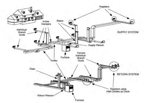
Figure 1.1: A common duct system 3
Figure 2.1: 4 basic component in HVAC system 6
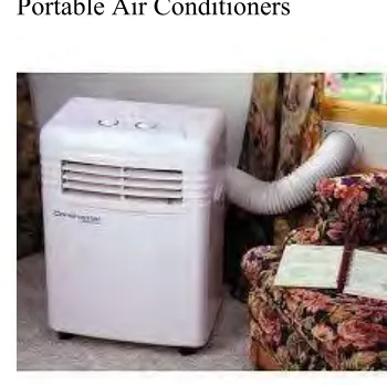
Figure 2.2: Portable Air Conditioner 7
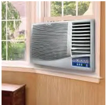
Figure 2.3: Window air conditioner 8
Figure 2.4:Ductless Mini-Split Air Conditioner 8 Figure 2.5: Packaged Terminal Air Conditioners (PTACs) 8
Figure 2.6: Air Cooled Package Unit (ACPU) 9
Figure 2.7: Water Cooled Package Unit (WCPU) 9
Figure 2.8: Central Hydronic System 9
Figure 2.9: Example mechanical ventilation 16
Figure 2.10: Formula of pressure 17
Figure 2.11: Inherent Characteristics of a Parallel and Opposed Blade Dampers 21
Figure 2.12: Centrifugal fan 23
Figure 2.13: Axial Fan 24
Figure 2.14: Type of centrifugal fan 25
Figure 2.15: Type of axial fan 25
Figure 3.1: Pitot tube 34
Figure 3.2: Pitot Traverse Tube 34
Figure 3.3: Anemometer 35
Figure 3.4: Pitot Traverse Tube with wireless device 35
Figure 3.5: Ladder 36
Figure 3.6: Measuring tape 36
Figure 3.7: Chiller Dun Han Bush 36
xiii
Figure 4.1: The mean pressure at Hole 1 40
Figure 4.2: The mean pressure at Hole 2 40
Figure 4.3: The mean pressure at Hole 3 41
Figure 4.4: The mean pressure at Hole 4 41
Figure 4.5: The mean pressure at Hole 5 42
Figure 4.6: The mean pressure at Hole 6 42
Figure 4.7: The mean pressure at Hole 7 43
Figure 4.8: The mean pressure at Hole 8 43
Figure 4.9: The total air pressure of all Hole in the ducting system 44
Figure 4.10: Mean pressure at Hole 3 45
Figure 4.11: Mean pressure at Hole 4 45
Figure 4.12: Mean pressure at Hole 5 46
Figure 4.13: Mean pressure in Hole 3, 4 and 5 46
Figure 4.14: Mean pressure at Hole 6 47
Figure 4.15: Mean pressure at Hole 7 48
Figure 4.16: Mean pressure at Hole 8 48
Figure 4.17: Mean pressure at Hole 6, 7 and 8 for damper 1 closed damper 2 open 49 Figure 4.18: The air pressure at Hole 1,2,3,4 and 5 with the speed of fan 50Hz 50 Figure 4.19: The total air flow rate at diffuser 1,2,3,4 and 5 51 Figure 4.20: The total air flow rate at diffuser 1, 2 and 3, at closed loop area 52 Figure 4.21: The total pressure at open loop area 53 Figure 4.22: The total pressure at closed loop area. 54 Figure 4.23: The total air velocity with all damper open at open loop area 55 Figure 4.24: The total air velocity with all damper open at closed loop area 55 Figure 4.25: The total air velocity with damper 1 open damper 2 closed 56 Figure 4.26: The total air velocity with damper 1 closed damper 2 open 57 Figure 4.27: The total air velocity using balometer at open loop area 58 Figure 4.28: The total air velocity using balometer at closed loop area 59 Figure 4.29: The total air velocity using balometer with damper 1 open damper 2
xiv
Figure 4.30: The total air velocity using balometer with damper 1 close
xv
LIST OF SYMBOLS AND ABBREVIATIONS
HVAC - Heating, Ventilating and Air-conditioning
PV - Photovoltaic
A - Area
- Specific heat capacity with constant volume E - Sun Total Power
g - Gravity
h - Height
m - Mass
- Mass Flow Rate
P - Pressure
- Difference in Pressure
- The amount of heat / heat radiation
R - Radius
S - Irradiance
- Temperature
- Difference in temperature
- Volume Flow Rate
W - Weight
- Emmissivity
- Stefan BoltzmannConstant
- Ratio of Circle Circumference to the Diameter RPM - Revolution Per Minute
CHAPTER 1
INTRODUCTION
1.0 Introduction
2
Based on the website ecofeet (2016) stated that refrigerant is a substance used in a heat cycle to transfer heat from one area, and remove it to another. Usually a gas at room temperature. Found in pretty much everything that cools, and sometimes in things that heat, most commonly air conditioners, fridges, freezers, and vehicle air conditioners. Traditionally, fluorocarbons, especially chlorofluorocarbons (CFC’s), were used as refrigerants, but they are being phased out because of their ozone depleting effects. Other common refrigerants used in various applications are ammonia, sulphur dioxide, and non-halogenated hydrocarbons such as propane. Most refrigerants found in end of life devices are ozone depleting and global warming inducing compounds. Example of refrigerant in the world is R12, R134A, R22, R410A, R290, R600, R600a, R601, R601a, and R717 (Briley, 2004).
In HVAC system the use of duct is very crucial as to deliver and circulate cool air to the targeted area. Basically, Duct systems are usually used in most commercial buildings, especially in office to transport conditioned air to the targeted space. Ducts are usually made from sheet metal or from a rigid fiberglass material, sometimes called fiberglass duct board. Smaller ducts often with a diameter 15 to 30 cm connected to air supply registers which is usually flexible ducts. Duct containing a helically wound wire for structural rigidity, a layer of coated non rigid fiberglass, and an exterior plastic sheet (Fisk et al., 2000).
3
4
1.1 Problem statement
Today we can see in Malaysia has an equatorial climate where rain and heat applied during the whole year. Malaysia is located on the equator of world globe which receiving sunlight 12 hours per day. So, most of the buildings in Malaysia are facing problem of how to prevent the direct sunlight, especially from east and west (Arifin & Denan, 2015). Therefore, the HVAC system was created to provide cold air and thermal comfort to the targeted area and people are in the vicinity. Cold air produced by the HVAC system channelled to the destination using the duct. Cold air-conditioning will be distributed according to the needs requested. Airflow from one point to another and from high pressure to low pressure. Every size of duct produced different amount of pressure depending the air flow rate, the size of the ducting and total friction between the wall and air. In this study, we will examine the effectiveness of pressure in each duct and other elements that play an important role in the flow rate of cold air to the place you want to go and return to the outside.
1.2 Objective
The main objective of this project are:
1. To determine effectiveness of ducting system by element duct pressure 2. To determine the frictional losses along duct walls in the ducting system
1.3 Supportive Objective:
5
CHAPTER 2
LITERATURE REVIEW
2.0 Introduction
Most commercial buildings in Malaysia used the ducting system to transport conditioned air to the targeted area. There are many factors affecting the effectiveness of ducting system which is duct pressure, size of ducting and friction loss. Duct pressure plays an important role in transporting the air as air flow from high pressure to low pressure (Int-Hout, 2015)..
2.1 Conventional Air Conditioning System
6
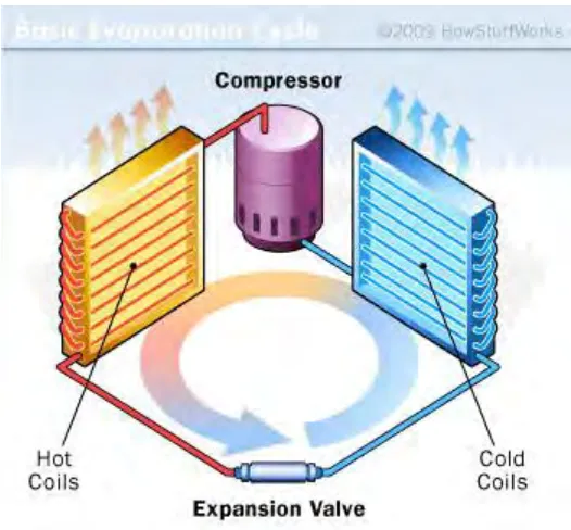
[image:22.612.185.448.122.366.2]system consists of 4 parts basic components which is compressor, condenser, expansion valve and evaporator. Below is the diagram 4 basic work in a system.
Figure 2.1: 4 basic component in HVAC system
7
The most every now and again utilized refrigeration cycle is the vapour pressure refrigeration cycle. Perfect vapour pressure refrigeration cycle results by dispensing with impracticalities connected with turned around Carnot cycle, for example, vaporizing the refrigerant totally before pressure, supplanting turbine with the throttling gadget (development valve or narrow tube). For the most part, household and modern fridge, aerating and cooling framework, heat pump and water cooler composed in light of the vapor pressure refrigeration cycle. (Upadhyay, 2014).
2.1.1 Type of Air Conditioner
In HVAC system, there three types of air conditioning system which is the individual system, unitary packaged system and central hydraulic system. Every type of system present different capability.
Individual system normally employs either a single, self-contained, packaged room air conditioner (installed in a window or through a wall) or separate indoor and outdoor units to serve an individual room.
[image:23.612.196.371.451.625.2]a) Portable Air Conditioners
8 Figure 2.3: Window air conditioner
[image:24.612.204.396.488.634.2]b) Ductless Mini-Split Air Conditioners
Figure 2.4:Ductless Mini-Split Air Conditioner