UNIVERSITI TEKNIKAL MALAYSIA MELAKA
OPTIMIZATION PERFORMANCE OF FIBER OPTIC SENSOR
ON SEMI-SYNTHETIC TEST OIL FOR ENGINE
TRADITIONALLY PURPOSE
This report is submitted in accordance with the requirement of Universiti Teknikal Malaysia Melaka (UTeM) for the Bachelor of Electronics Engineering Technology
(Telecommunications) with Honours.
by
MOHD SHAIFUL AZRI BIN NUS B071310209
910410-06-5361
ii
UNIVERSITI TEKNIKAL MALAYSIA MELAKA
BORANG PENGESAHAN STATUS LAPORAN PROJEK SARJANA MUDA
TAJUK: Optimization Performance of Fiber Optic Sensor on Semi-Synthetic Test Oil for Engine Traditionally Purpose
SESI PENGAJIAN: 2016/17 Semester 1
Saya MOHD SHAIFUL AZRI BIN NUS
mengaku membenarkan Laporan PSM ini disimpan di Perpustakaan Universiti Teknikal Malaysia Melaka (UTeM) dengan syarat-syarat kegunaan seperti berikut:
1. Laporan PSM adalah hak milik Universiti Teknikal Malaysia Melaka dan penulis. 2. Perpustakaan Universiti Teknikal Malaysia Melaka dibenarkan membuat salinan
untuk tujuan pengajian sahaja dengan izin penulis.
3. Perpustakaan dibenarkan membuat salinan laporan PSM ini sebagai bahan pertukaran antara institusi pengajian tinggi.
4. **Sila tandakan ( )
SULIT
TERHAD
TIDAK TERHAD
(Mengandungi maklumat yang berdarjah keselamatan atau kepentingan Malaysia sebagaimana yang termaktub dalam AKTA RAHSIA RASMI 1972)
(Mengandungi maklumat TERHAD yang telah ditentukan oleh organisasi/badan di mana penyelidikan dijalankan)
Alamat Tetap:
B-33 Felda Raya Jengka 14,
26400 Bandar Jengka,
Pahang Darul Makmur.
Tarikh: ________________________
Disahkan oleh:
Cop Rasmi:
Tarikh: _______________________
iii
DECLARATION
I hereby, declared this report entitled “Optimization Performance of Fiber Optic Sensor on Semi-Synthetic Test Oil for Engine Traditionally Purpose” is the results
of my own research except as cited in references.
Signature : ……….
Author’s Name : MOHD SHAIFUL AZRI BIN NUS
iv
APPROVAL
This report is submitted to the Faculty of Engineering Technology of UTeM as a partial fulfillment of the requirements for the degree of Bachelor of Electronics Engineering Technology (Telecommunications) with Honours. The member of the supervisory is as follow:
v
ABSTRAK
vi
ABSTRACT
vii
DEDICATION
This humble effort specially dedicated to my beloved parents, family, lecturers and friends, whose love can never be forgotten for their support, guidance and
viii
ACKNOWLEDGEMENT
ix
TABLE OF CONTENT
Declaration iii
Approval iv
Abstrak v
Abstract vi
Dedication vii
Acknowledgement. viii
Table of Content ix
List of Tables. xiii
List of figures xiv
List of Abbreviations, Symbols and Nomenclatures . xvi
CHAPTER 1: INTRODUCTION 1
1.1 Introduction 1
1.2 Project Background 1
1.3 Objectives 3
1.4 Project Scope 3
1.5 Thesis Outline 4
CHAPTER 2: LITERATURE REVIEW 5
2.1 Introduction 5
2.2 Fiber Optic 5
Basic Fiber Optic Communication System 6
x
2.3 Type of Fiber Optic 9
Multimode Fiber 9
Multimode Step-Index Fiber 10
Multimode Graded-Index Fiber 11
Single-Mode Fiber 11
2.4 How Fiber Optic Works 13
Total Internal Reflection 14
2.5 Advantages and Disadvantages of Fiber Optic 15
Advantages of Fiber Optic 15
Disadvantages of Fiber Optic 17
2.6 Light Source 18
LED (Light Emitting Diode) 18
Laser Diodes 20
2.7 Fiber Optic Sensor 21
Fiber Optic Sensor Principles 22
2.8 Lubricant Engine Oil 24
Classification of Lubricating Oils 25
Lubricant Engine Oil Selection 25
2.9 Design of Experiment (DOE) 26
Factorial Designs 27
CHAPTER 3: METHODOLOGY 30
3.1 Introduction 30
3.2 Project Methodology 30
3.3 Title Finding 32
3.4 Problem Identification 32
xi
3.5 Literature Review 34
3.6 Identified Variables 35
3.7 Develop Sensor 36
Hardware and Equipment 37
3.8 Testing Sensor 38
3.9 Applying Design of Experiment Method 39
Factor Level Definition 39
Choice of Design 39
3.10 Analyze Sensor 40
3.11 Writing Formal Report 41
3.12 Project Overview 41
CHAPTER 4: RESULT & DISCUSSION 43
4.1 Introduction 43
4.2 Optical Fiber Sensor Diagram 43
4.3 Fiber Optic Semi-Synthetic Engine Oil Data Collection 45
4.4 Analysis of Design Expert Results 46
Analysis of Half-Normal Plot 46
Analysis of Normal Plot 47
Analysis of Variance (ANOVA) 49
Analysis of Normal Plot Residuals 51
Analysis of Residuals vs Predicted 51
Analysis of Residuals vs Run 52
Analysis of Factor Interaction of Type of fiber 53
Analysis of Factor Interaction of Concentration 54
Analysis of Factor Interaction of Type of Fiber and Concentration 55
xii
Regression Model 57
Final Equation in Terms of Coded Factors 57
Final Selected Factors 57
CHAPTER 5: CONCLUSION & FUTURE WORK 59
5.1 Introduction 59
5.2 Discussion and Conclusion for Chapter 3 59
5.3 Discussion and Conclusion for Chapter 4 60
5.4 Future Work 60
REFERENCES 62
APPENDICES
Appendix A – GUI User Guide
xiii
LIST OF TABLES
Table 2.1: Characteristics of Each Type of Optical Fibers and Their Applications
(Lucia 2011) 9
Table 2.3: LED vs Laser 18
Table 3.1: Factors and Levels for Full-Factorial Design Example 39
Table 4.1: Results of Semi-Synthetic Engine Oil Concentration And Power Output Measurements 45
Table 4.2: Analysis of Variance (ANOVA) 49
Table 4.3: The Constraints 57
xiv
LIST OF FIGURES
Figure 2.1: Fiber Optic 6
Figure 2.2: Basic Fiber Optic Communication System (Massa 2008) 7
Figure 2.3: Fiber Optic Cable Construction 8
Figure 2.4: Total Internal Reflection In Multimode Step-Index Fiber (Lucia 2011) 10 Figure 2.5: Multimode Graded-Index Fiber (Lucia 2011) 11
Figure 2.6: Single-Mode Fiber (Lucia 2011) 12
Figure 2.7: Cross-Section Of Polarization-Maintaining Fiber (Lucia 2011) 13
Figure 2.8: Diagram For The Total Internal Reflection (Reddy 2014) 14
Figure 2.9: Principle of Internal Reflection (Reddy 2014) 15
Figure 2.10: Surface-Emitting Versus Edge-Emitting Diodes (Massa 2008) 19
Figure 2.11: Fourteen-Pin Butterfly Mount Distributed Feedback Laser Diode (Education 2008) 21
Figure 2.12: Basic Components Of An Optical Fiber Sensor System (Fidanboylu & Efendioglu 2009) 22
Figure 2.13: Extrinsic and Intrinsic Types of Fiber Optic Sensors. (Fidanboylu & Efendioglu 2009) 23
Figure 2.14: Example of Factorial Design (Montgomery 2013) 28
Figure 2.15: The 23 Design (Montgomery 2013) Geometric View, Design Matrix and Table 28
Figure 2.16: The Algebraic Sign For Calculating Effects In The 23 Design (Montgomery 2013) 29
Figure 3.1: Step of Project Methodology for the project 31
Figure 3.2: Define The Objective of The Problem 32
Figure 3.3: Input Variable Selection 33
Figure 3.4: Single-mode and Multi-mode Type of Fiber That Used in This Project 35 Figure 3.5: Stripping The Fiber Optic and Remove The Cladding 36
Figure 3.6: Cleaving Process 36
xv
Figure 3.8: Cleaning and Cutter Tools 37
Figure 3.9: Splicing Machine 38
Figure 3.10: The Semi-synthetic Engine Oil Dripped onto The Optical fiber sensor 38 Figure 3.12: Two-Level Factorial Design Builder 40
Figure 3.13: Flow Chart of Design of Experiment Using Factorial Design 42
Figure 4.1: Schematic of single-mode optical fiber sensor for semi-synthetic engine oil concentration 44
Figure 4.2: Schematic of multi-mode optical fiber sensor for semi-synthetic engine oil concentration 44
Figure 4.3: Variation of Output With 16 Responses 46
Figure 4.4: The Half-Normal Plot Graph is Significant 47
Figure 4.5: The Normal Plot Graph is Significant 48
Figure 4.6: The Normal Plot of Residuals Graph 51
Figure 4.7: The Residuals vs Predicted Response Values Graph 52
Figure 4.8: The Residuals vs Run Plot Graph 53
Figure 4.9: One Factor Graph (Type of Fiber) 54
Figure 4.10: One Factor Graph (Concentration) 55
xvi
LIST OF ABBREVIATIONS, SYMBOLS AND
NOMENCLATURES
FOS - Fiber Optic Sensor
DOE - Design of Experiment
OFAT - One Factor at a Time Method
TQM - Total Quality Management
TPM - Target Performance Measure
NPM - Noise Performance Measure
LED - Light Emitting Diode
FFD - Full Factorial Design DFSS - Design for Six-Sigma
IDDM - Insulin Dependent Diabetes Mellitus NIDDM - Non-Insulin Dependent Diabetes Mellitus
MMF - Multi-Mode Fibers
SMF - Single-Mode Fibers
PCS - Plastic-Clad Silica
ASE - Amplified Spontaneous Emission
OSA - Optical Spectrum Analyzer
ANOVA - Analysis of Variance
LRIS - Liquid Refractive Index Sensor SPR - Surface Plasmon Reverberation
dB - Decible
nm - Nanometer
1
CHAPTER 1
INTRODUCTION
1.1 Introduction
This chapter is covered some topics. There is the background of project’s title, problem statement faced, the objective of this project, project scopes, thesis outline and finally project’s conclusion.
1.2 Project Background
These days, speed of data transmission is being given a prior for human being to perform well in their specific field of task. Speed of data is being concerned especially for engines and communication, where it helps human in their daily life. Fiber optic has become communication medium of choice for mobile phones, telephone, security camera, industrial network and so on. that related with kind of communication. The biggest advantage of optical fiber is most cost effective in transporting information.
In addition, easy realization and better sensitivity make fiber optic sensor is a better alternative compared to traditional copper cables. The fiber optic sensor is exceptionally encouraging range for business applications because of cost adequacy, simple acknowledgment, affectability and little in size. Furthermore, fiber optic sensor has become very popular in areas such as petrochemical, pharmaceutical and process control.
2 to 30% synthetic oil. Semi-synthetic engine oil can give engine safeguard to some degree higher temperatures and genuinely overwhelming burdens and they are not as subject to vanishing as the normal mineral oil.
Semi-synthetic engine oil can be a decent decision for drivers who put overwhelming burdens on their engine amid serious use circumstances like towing. Semi-synthetic engine oil is intended to have a hefty portion of the advantages of synthetic oil, for example, augmented ointment life and enhanced thickness files yet are for the most part lower cost than a full manufactured oil. The primary semi-synthetic engine oil was presented in 1966.
Semi-synthetic engine oil usually used in engine and to serve to absorb pressure and friction that can cause damage to engine components. At one stage the oil will become thick and black. Thus, a fiber optic sensor was developed to detect the condition on semi-synthetic engine oil whether the oil is still in good condition or not. By developing this project fiber optic sensor can be applied inside the engine. This is because fiber optic sensors very good for detecting the condition and concentration of the liquid. However, this sensor will be improving performance by using a statistical technique known as Design of Experiment (DOE). This procedure is a technique to decide the relationship between factor affecting a process and the output of that process. In other word, it is utilized for discover circumstances and end results connections. This data was expected to oversee handle contribution to request to optimize the output.
1.2 Problems Statement
3 kilometres. This is because engine oil will become thick and black. So, for this project one fiber optic sensor was developed to detect the condition on semi-synthetic engine oil. By developing this fiber optic sensor, it can be applied inside the engine.
1.3 Objectives
There are three main objectives in this study that bring project's success. The objectives of the project are:
1) To study Fiber Optic Sensor (FOS).
2) To develop fiber optic sensor for detect condition semi-synthetic engine oil. 3) To analyze performance of fiber optic sensor using Design of Experiment
(DOE).
1.4 Project Scope
For to complete the objective of the project, the scope has been outlined. In Bachelor Degree Project 1, literature review and methodology has been included which more related about the project research and concept of fiber optic sensor. Next, for Bachelor Degree Project 2 will focus on experiment result and discussion.
The scope of study includes:
1) The study and understanding of fiber optic sensor.
2) Understanding the effects of semi-synthetic engine oil on fiber optic sensors. 3) Fiber optic to be used as a sensor.
4
1.5 Thesis Outline
The thesis outline is dividing into two parts which are Bachelor Degree Project 1 and Bachelor Degree Project 2. The outline as follows:
1) Bachelor Degree Project 1 Report
The introduction is briefly discussed in Chapter 1. In this chapter, the background of the research such as objective, problem statement and project scope are mentioned. Chapter 2 is about literature view from previous research concerning on fiber optic. The methodology and procedures applied for this study are explained details in Chapter 3.
2) Bachelor Degree Project 2 Report
5
CHAPTER 2
LITERATURE REVIEW
2.1 Introduction
Literature study is where knowledge and ideas that was established in topic defined. Discussion on problem issue, objective of the study and methodology used supported by knowledge that is steady that again from books, journal, article and website that are related. Before design the fiber optic sensor for detect semi-synthetic engine oil, must understanding the concept of fiber optic and how it works. Fiber optic concept in this chapter explained more thoroughly. In addition, the previous research based on fiber optic sensor, Design of Experiment (DOE), semi-synthetic engine oil and light sources also included on this chapter.
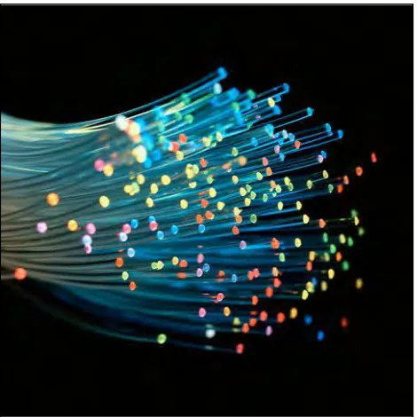
2.2 Fiber Optic
6 bundle so that they can give various other applications, including sensor and fiber laser. It used as light driver in medical and other applications where bright light need to shine on target without line-of-sight route that is clear. Numerous magnifying lens utilize fiber optic light sources to give extraordinary enlightenment of tests being contemplated. (Reddy 2014)
Figure 2.1: Fiber Optic
(Source: http://www.ledlightmake.com/led-fiber-optic-illuminators-c-94_95/)
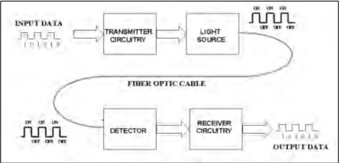
Basic Fiber Optic Communication System
7 silicon detector, and a few easy electronic circuits. On the other hand, system that commonly used to long distance, broadband telecommunication that is high which uses part wavelength multiplexing, erbium-doped amplifier fiber, modulation out use DFB laser with temperature compensation, Bragg's fiber grating, and infrared photodetectors high speed can cause tens cost or hundreds of thousand dollars. Basic question is "how many information that will be sent and how far it need to go?" With this we will study various components which form a fiber optic communication system and consideration that should be taken into consideration in the system design. (Massa 2008)
Figure 2.2: Basic Fiber Optic Communication System (Massa 2008)
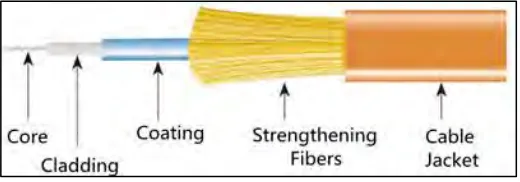
Fiber Optic Cable Construction
Figure 2.3 show fiber optic cable construction. There are several materials which uses in element in fiber optic cable like core, cladding, layer, strengthening fiber and cable jacket. Every single element in fiber optic cable have special role.
According to (Awad 2006), core that is central area, made of silica or doped silica, is incident places fiber light emitter. Core is material shaped tube post dielectric and to most made from glass. Light propagate most along fiber core.
8 of refraction. Cladding material refractive index not as much as that core material. this cladding generally made of glass or plastic. cladding who implement function like reduce eclipse from core on air around, reduce loss spread in core surface, protect fiber from absorbing pollutant surface and increase mechanical strength.
After that, coating is major non-optic layer around the cladding. This layer usually comprises than one or over polymer layer that ensure silica structure towards physical injury or ecology. the coating being stripped when connectorized fiber or fusion connected. Layer or buffer is layers of material used to protect fiber optic from physical danger. Material used for buffer is a type of plastic.
[image:24.595.186.446.385.476.2]The strengthening fiber, this segment ensure core towards destroy powers and tension that is excess during installation. Materials that can run from Kevlar sheet wire to gel arm filled. Lastly, cable jacket is cable outer layer. Most optic fiber cable have orange jacket although some type can have yellow jacket, black or other. Various colours can be used to determine different applications in network.
Figure 2.3: Fiber Optic Cable Construction