This is a repository copy of What Are the Biomechanical Properties of the Taylor Spatial Frame™?.
White Rose Research Online URL for this paper: http://eprints.whiterose.ac.uk/110891/
Version: Accepted Version
Article:
Henderson, DJ, Rushbrook, JL, Harwood, PJ et al. (1 more author) (2017) What Are the Biomechanical Properties of the Taylor Spatial Frame™? Clinical Orthopaedics and Related Research®, 475 (5). pp. 1472-1482. ISSN 0009-921X
https://doi.org/10.1007/s11999-016-5182-8
© 2016, The Association of Bone and Joint Surgeons. This is an author produced version of a paper published in Clinical Orthopaedics and Related Research. The final publication is available at Springer viahttps://doi.org/10.1007/s11999-016-5182-8. Uploaded in
accordance with the publisher's self-archiving policy.
[email protected] https://eprints.whiterose.ac.uk/ Reuse
Unless indicated otherwise, fulltext items are protected by copyright with all rights reserved. The copyright exception in section 29 of the Copyright, Designs and Patents Act 1988 allows the making of a single copy solely for the purpose of non-commercial research or private study within the limits of fair dealing. The publisher or other rights-holder may allow further reproduction and re-use of this version - refer to the White Rose Research Online record for this item. Where records identify the publisher as the copyright holder, users can verify any specific terms of use on the publisher’s website.
Takedown
If you consider content in White Rose Research Online to be in breach of UK law, please notify us by
What Are the Biomechanical Properties of the Taylor Spatial FrameTM?
Running title: Taylor Spatial FrameTM Mechanical Stability
Daniel J. Henderson FRCS (Orth), Jeremy L. Rushbrook FRCS (Orth), Paul J. Harwood FRCS (Orth), Todd D. Stewart PhD
Received: July 13, 2016 Accepted:
D. J. Henderson, J. L. Rushbrook, P. J. Harwood
Department of Orthopaedics, Leeds General Infirmary, Leeds, UK
D. J. Henderson, J. L. Rushbrook, T. D. Stewart
Institute of Medical and Biological Engineering, School of Mechanical Engineering, University of Leeds, Leeds, UK
This research is supported by the National Institute for Health Research (NIHR) Leeds Musculoskeletal Biomedical Research Unit (TDS)
The views expressed are those of the authors and not necessarily those of the NHS, the NIHR, or the Department of Health.
All ICMJE Conflict of Interest Forms for authors and Clinical Orthopaedics and Related Research® editors and board members are on file with the publication and can be viewed on request.
Clinical Orthopaedics and Related Research® neither advocates nor endorses the use of any treatment, drug, or device. Readers are encouraged to always seek additional information, including FDA-approval status, of any drug or device prior to clinical use.
This work was performed in the laboratories of the Institute of Medical and Biological Engineering, University of Leeds, Leeds, UK.
D. J. Henderson
Department of Orthopaedics Leeds General Infirmary Great George Street Leeds, LS1 3EX, UK
Abstract
Background The Taylor Spatial Frame TM (TSF) is a versatile variant on the traditional
Ilizarov circular fixator. Although in widespread use, little comparative data exist to quantify
the biomechanical effect of substituting the tried-and-tested Ilizarov construct for the TSF
hexapod system.
Questions/purposes This study was designed to investigate the mechanical properties of the
TSF system under physiologic loads, with and without the addition of a simulated bone
model, with comparison to the standard Ilizarov frame.
Methods The mechanical behaviors of three identical four-ring TSF and Ilizarov constructs
were tested under levels of axial compression, bending, and rotational torque to simulate
loading during normal gait. An acrylic-pipe fracture model subsequently was mounted, using
fine wires and 5 mm half pins, and the testing was repeated. Load-deformation curves, and so
rigidity, for each construct were calculated, with statistical comparisons performed using
paired t-tests.
Results Under axial loading, the TSF was found to be less rigid than the Ilizarov frame (645
57 N/mm versus 1269 256 N/mm; mean difference, 623 N/mm; 95% CI, 438.3-808.5
N/mm; p < 0.001), but more rigid under bending and torsional loads (bending: 42 9
Nm/degree versus 78 13 Nm/degree; mean difference, 37 Nm/degree; 95% CI, 25.0–47.9
Nm/degree; p < 0.001; torsion: 16 2 Nm/degree versus 5 0.35 Nm/degree; mean
difference, 11 Nm/degree; 95% CI, 9.5–12.2 Nm/degree; p < 0.001). On mounting the bone
models, these relationships broadly remained in the half-pin and fine-wire groups, however
the half-pin constructs were universally more rigid than those using fine wires. This effect
resulted in the TSF, using half pins, showing no difference in axial rigidity to the fine-wire
to 7.1 N/mm; p > 0.999), while retaining greater bending and torsional rigidity. Throughout
testing, a small amount of laxity was observed in the TSF construct on either side of neutral
loading, amounting to 0.72 mm ( 0.37 mm) for change in loading between -10 N and 10 N
axial load, and which persisted with the addition of the synthetic fracture model.
Conclusions This study broadly shows the TSF construct to generate lower axial rigidity, but
greater bending and torsional rigidity, when compared with the Ilizarov frame, under
physiologic loads. The anecdotally described laxity in the TSF hexapod strut system was
shown in vitro, but only at low levels of loading around neutral. It also was shown that the
increased stiffness generated by use of half pins produced a TSF construct replicating the
axial rigidity of a fine-wire Ilizarov frame, for which much evidence of good clinical and
radiologic outcomes exist, while providing greater rigidity, and so improved resistance, to
potentially detrimental bending and rotational shear loads.
Clinical Relevance If replicated in the clinical setting, these findings suggest that when using
the TSF, care should be taken to minimize the observed laxity around neutral with
appropriate preloading of the construct, but that its use may produce constructs better able to
resist bending and torsional loading, although with lower axial rigidity. Use of half pins in a
TSF construct however may replicate the axial mechanical behavior of an Ilizarov construct,
Introduction
It is recognized that the biomechanical environment at a fracture or osteotomy site is one of
the key factors in the process of bone healing [16]. One of the more powerful tools at the
surgeon’s disposal in influencing this environment is circular external fixation using the
Ilizarov technique. The use of modular circumferential rings connected by longitudinal
treaded rods, with an almost limitless combination of bone-fixation fine wires or half pins,
allows each frame construct to be tailored to each patient’s individual needs. When applied
appropriately, there is much evidence that circular fixation generates beneficial levels of axial
micromotion during weightbearing while limiting deleterious shear strain [14, 17, 23, 26].
This combination is thought to generate an osteogenic mechanical environment [8, 10, 11, 17,
36], and the biomechanical theory has been supported by clinical results [12, 33].
More recently, substitution of the threaded rods of the traditional Ilizarov frame for a
hexapod system of six telescopic struts at the focal level, like in the Taylor Spatial FrameTM
(TSF) (Smith & Nephew Inc, Memphis, TN, USA), has allowed more versatile application of
circular fixation. This arrangement allows manipulation of a fracture or osteotomy site with
six degrees of freedom by differentially altering the length of the six struts. This allows
simultaneous correction of multiplane deformity and distraction and compression in a much
simpler manner than would be possible using traditional Ilizarov equipment and with several
reports of good clinical and functional outcomes after such treatment [1, 19, 35]. Numerous
studies exist in the literature investigating and describing the potential effects of altering any
one of the modular parts of a traditional Ilizarov circular frame on the biomechanical
environment at a fracture site [2, 20, 23, 24, 27], however there are almost no studies
examining the biomechanical behavior of a hexapod construct [21] and none, to our
an Ilizarov fixator for the six struts of a hexapod may have on the overall behavior of a
fixator construct, and therefore on the mechanical environment of a fracture site. Given the
existing body of evidence comparing in vitro biomechanical behavior of circular frames with
clinical outcomes, and the ever-expanding understanding of the complexities of bone healing
biomechanics, a biomechanical comparison was planned to better understand the behavior of
the TSF in isolation, but also to see whether any observed differences in the behavior of the
frame components in isolation persisted once the effect of bone-fixation elements in the
simulated fracture model were added, and therefore whether any clinically important effect
was likely to result from substitution of a TSF for a traditional Ilizarov frame.
This biomechanical study therefore was designed to answer the following research questions:
(1) What are the mechanical load-deformation characteristics of the TSF construct alone, and
how does this compare with the standard Ilizarov frame under physiologic levels of axial
compression, axial torsion, and bending loads? (2) How are these characteristics altered when
tested with the addition of mounted bone models using fine wires or half pins?
Materials and Methods
An experimental biomechanical study was designed testing Ilizarov and TSF constructs of
identical dimensions alone and with a bone model mounted using fine wires and half pins. An
acrylic tube with an outer diameter of 32 mm and a 4-mm wall (Clear Plastic Supplies,
Chesterfield, UK) was used as a mechanical substitute for bone. This symmetric, uniform
model was chosen to minimize any variability between testing cycles that may be caused by
minor differences in wire placement in more anatomic models or by bone density variation in
cadaveric samples, a common practice in similar mechanical studies [20, 24, 25, 27, 28, 30,
31]. While not attempting to reproduce a directly clinically comparable environment, the
differences with small sample sizes, a finding confirmed by the low variance observed in
preliminary testing and which was used to guide the sample size for this study.
Three identical four-ring frames for each of the six configurations tested were constructed
according to manufacturers’ specifications using 155-mm aluminum TSF rings (Smith &
Nephew Inc). These were assembled with 50-mm spacing between common segment rings,
spanned by four 6-mm threaded rods, and 175-mm spacing across the unstable focal segment.
This was spanned with six medium TSF FAST-FXTM struts (Smith & Nephew Inc) for the
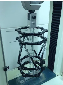
TSF constructs or four 6-mm threaded rods for the Ilizarov constructs (Fig. 1).
After testing the frame elements alone, bone models were mounted using new clinical
standard 1.8-mm smooth wires tensioned to 130 kg or predrilled self-tapping 5-mm half pins.
To maximize reproducibility and isolate the effect of the frame construct, in keeping with
previous studies [6, 20, 27, 31], bone models were mounted centrally in each ring with
fixation elements placed at theoretically “ideal” crossing angles of 90°. To prevent bone
apposition during loading, simulating an entirely unstable fracture or corticotomy, bone
models were mounted with a 20-mm fracture gap.
Constructs were mounted in the testing apparatus (Tinius Olsen H25K-S UTM; Tinius Olsen
Inc, Horsham, PA; and Uniaxial manual torsion testing machine; University of Leeds, Leeds,
UK) with bespoke mounting jigs allowing rigid fixation of the frame constructs, and bone
substitutes, to the apparatus (Fig. 2). Constructs were tested separately under axial loading,
AP bending, and axial torsion up to 700 N, 20 Nm, and 20 Nm, respectively, at loading rates
of 6 mm/minute/1.01°/minute and with data being collected only after three preconditioning
cycles of full loading. Data were recorded for three testing cycles for each construct
configuration. Physiologic loading was considered to consist of 500 N axial loading, 20 Nm
bending, and 5 Nm torsional load, being analogous to loads shown to be supported by a tibial
Data were collected and collated using Microsoft® Excel® (Microsoft Corporation, Redmond,
WA, USA) with data sets transferred for graph plotting and statistical analysis to Graph Pad
Prism® (Version 6; GraphPad Software, Inc, La Jolla, CA, USA). Load deformation curves
were created for each construct configuration and loading regime for the full range of
loading. Nonlinear regression analysis then was performed to determine the construct
rigidity, defined as the mean slope of the linearly elastic portion of the load deformation
curve. Rigidity in this context refers to the mechanical load-deformation properties of a
complex structure such as a circular frame, as opposed to stiffness, being a property of a
uniform material. Analyses were done to examine for statistically significant differences in
rigidity between constructs. The data met assumptions for parametric testing using the
D’Agostino and Pearson omnibus test and QQ-plot analysis and therefore Student’s t-test and
ANOVA testing with post hoc analysis using Tukey’s method were performed. This
methodology is validated in small sample-size studies and commonly applied to such
mechanical modeling studies where conditions are almost entirely controlled and comparison
between two samples, with low variance, is required [7, 20, 25]. While recognizing the
potential for type II error with small sample sizes, a p value less than 0.05 was considered
statistically significant throughout.
Results
Frame Elements Alone
Axial loading of the Ilizarov frame in isolation produced a mean rigidity of 1269 N/mm (
256 N/mm) for the linear portion of its load-deformation curve (Fig. 3A). By contrast, the
TSF showed a lower mean rigidity on axial loading of 645 N/mm ( 57 N/mm; mean
difference, 623 N/mm; 95% CI, 438.3-808.5 N/mm; p < 0.001) (Fig. 4A). Additionally, while
loading of the Ilizarov produced a largely linear trend in deformation, axial loading of the
around neutral, representing a mean deformation of 0.72 mm ( 0.37 mm) for a change in
load from 10 N distraction to 10 N compression, before a linear relationship returned.
Under bending loads, the Ilizarov frame produced a mean rigidity of 42 Nm/degree ( 9
Nm/degree), less rigid than the TSF at 78 Nm/degree ( 13 Nm/degree; mean difference, 37
Nm/degree; 95% CI, 25.0–47.9 Nm/degree; p < 0.001) (Fig. 4B). Once again, and again in
contrast to the Ilizarov, the load-deformation curve of the TSF generated a marked toe region,
representing 0.5° ( 0.16°) deformation from -5 to 5 Nm loading (Fig. 3B).
On torsional testing, the TSF construct had a rigidity of 16 Nm/degree ( 2 Nm/degree),
higher than that of the Ilizarov at 5 Nm/degree ( 0.35 Nm/degree; mean difference, 11
Nm/degree; 95% CI, 9.5–12.2 Nm/degree; p < 0.001) (Fig. 4C). Again there was an initial
nonlinear toe region to the load deformation curve with 10 Nm loading around neutral
producing 2° ( -0.13°) deformation from -5 to 5 Nm (Fig. 3C).
Bone-frame Constructs
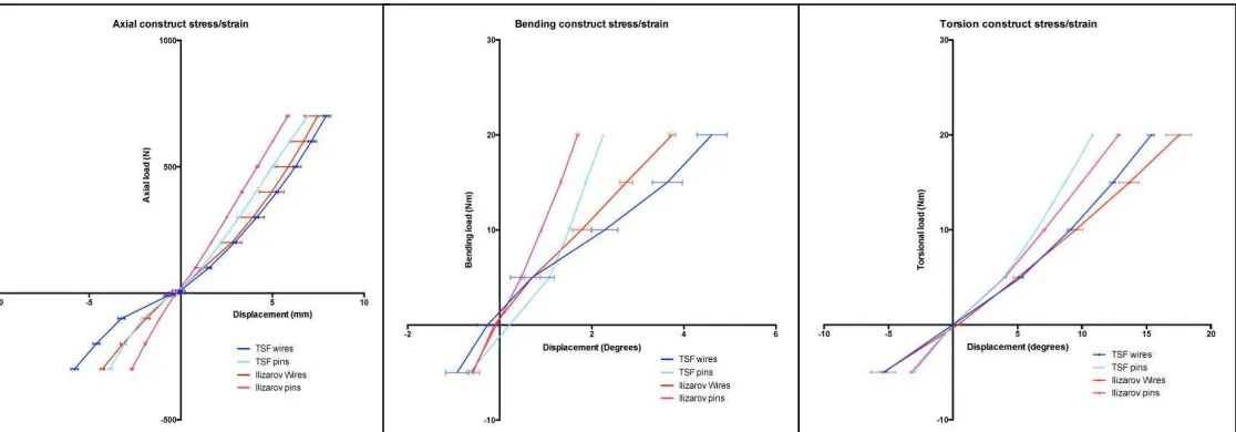
Axial loading of the all fine-wire constructs showed the fine-wire Ilizarov frame to be
slightly more rigid than the fine-wire TSF (107 4 N/mm versus 100 1.7 N/mm; mean
difference, 7 N/mm; 95% CI, 0.09–14.2 N/mm; p = 0.047). Both constructs produced
nonlinear load-displacement curves, with initially increasing construct rigidity followed by
more linear behavior (Fig. 5A). In both constructs a toe region of laxity in the load
deformation curves was observed between -10 N and 10 N loading with no difference seen,
with the numbers available, between the two designs (0.7 0.03 mm versus 0.5 0.04 mm;
mean difference, 0.17 mm; 95% CI, -0.07 to 0.41 mm; p = 0.178) (Table 1). Axial loading of
half-pin constructs produced similar results with the half-pin TSF less rigid at 107 N/mm ( 3
N/mm) than the half-pin Ilizarov at 120 N/mm ( 0.7 N/mm; mean difference, 13 N/mm;
Notably, however, the half-pin TSF construct showed no difference in rigidity from the
fine-wire Ilizarov, with the numbers available, in the linear phase of loading (107 3 N/mm
versus 107 4 N/mm; mean difference, 0.05 N/mm; 95% CI, -6.99 to 7.1 N/mm; p > 0.999).
Again there was a demonstrable initial toe phase of laxity in the half-pin TSF construct with a
mean deformation of 0.5 mm ( 0.08 mm) for 10 N around neutral loading, greater than that
observed in the half-pin Ilizarov at 0.25 mm ( 0.16 mm; mean difference, 0.25 mm; 95% CI,
0.01–0.48 mm; p = 0.042). In the fine-wire TSF and Ilizarov, however, there was no
difference in the toe-phase observed with the numbers available (0.7 0.03 mm versus 0.5
0.04 mm; mean difference, 0.17 mm; 95% CI, -0.07 to 0.41 mm; p = 0.178).
Application of bending forces to the half-pin constructs produced similar results to the frames
tested in isolation, with the TSF more rigid at 13 Nm/degree ( 0.2 Nm/degree) than the
half-pin Ilizarov at 12 Nm/degree ( 0.1 Nm/degree; mean difference, 0.6 Nm/degree; 95% CI,
0.1–1.1 Nm/degree; p = 0.013). Again, a higher degree of toe-phase laxity was observed for
5-Nm loading around neutral (1.7° 0.01 versus 1.1° 0.03; mean difference, 0.7; 95%
CI, 0.3–1.0; p = 0.001) (Fig. 5B). In contrast, bending loading of the fine-wire constructs
reversed the relationship seen in the frames alone, with lower rigidity observed in the
fine-wire TSF at 4 Nm/degree ( 0.2 Nm/degree) than the fine-wire Ilizarov construct at 5
Nm/degree ( 0.2 Nm/degree; mean difference, 1.2 Nm/degree; 95% CI, 0.7–1.6 Nm/degree;
p < 0.001). This bending testing of the fine-wire constructs did show unexpectedly high
levels of deformation under physiologic loads, particularly in the TSF construct, with an
element of deformation occurring through sliding of the bone models along the smooth fine
wires.
Under torsional loads, the fine-wire and half-pin constructs behaved similarly to frames
Nm/degree ( 0.02 Nm/degree) and 2 Nm/degree ( 0.02 Nm/degree), respectively, than the
comparable Ilizarov constructs at 1.2 Nm/degree ( 0.06 Nm/degree; mean difference, 0.3
Nm/degree; 95% CI, 0.19–0.38 Nm/degree; p < 0.001) and 1.7 Nm/degree ( 0.04
Nm/degree; mean difference, 0.5 Nm/degree; 95% CI, 0.39–0.58 Nm/degree; p < 0.001)(Fig.
5C).
Discussion
The widespread uptake of hexapod systems such as the TSF with use of circular-frame
constructs has simplified ring-fixation techniques in complex clinical scenarios, allowing
successful management in cases that previously might have been considered highly
technically challenging [4, 9, 35]. The majority of clinical and preclinical evidence regarding
use and outcomes of circular external fixation is based on traditional Ilizarov equipment with
some prior studies characterizing the effect of altering aspects of Ilizarov construct design on
fracture mechanics [6, 11, 23, 28]. This knowledge, along with an understanding of the
fracture-site mechanical environment and bone healing, allows a surgeon to tailor
construction of a frame to suit the particular clinical scenario and therefore it is vital to
understand what effect exchanging hexapod struts for threaded rods might have on the
mechanical behavior of a circular frame construct so that this may be taken into account
during preoperative planning. This mechanical study showed that the TSF hexapod frame is
less rigid than the Ilizarov frame under axial loading, but more rigid under bending and
torsional loading, however these differences became far less, if at all, apparent when tested as
part of a frame construct with fine-wire or half-pin bone fixation elements included. The TSF
showed an increased element of laxity around neutral loading in all planes compared with the
Ilizarov, a difference which became far less apparent in the context of the fine-wire
As an experimental biomechanical study, this study has certain limitations that must be taken
into account in the interpretation and clinical translation of the results. As far as possible, the
experimental design aimed to limit the potential variables between frames to focus
specifically on the fundamental mechanical behavior of the TSF and Ilizarov frames and
optimize reproducibility between testing cycles and constructs. Given this, it is not intended
to consider the multitude of possible combinations in which a frame may be used, and
therefore is not a clinical comparison of the Ilizarov versus the TSF. Each clinical case is
different and the correct frame construct design remains up to the treating clinician, for
example attempting to place a frame that seeks to minimize shear strain in an unstable
transverse tibial fracture. The intention of this study is to help inform preoperative planning
by providing a clearer understanding of what effect use of a TSF in place of an Ilizarov frame
might have on the overall construct rigidity under physiologic loading conditions. Acrylic
pipe as a bone model, while not replicating the geometry or anatomy of bone, was chosen as
a symmetric, uniform and rigid analog, allowing simulation of bicortical fixation and stress
distribution of wires and pins, while not influencing the comparative mechanical behavior of
the constructs [5]. The advantage of this uniformity, when used with idealized fine-wire and
half-pin crossing angles, lies in the reproducibility of the construction and loading of each
frame so minimizing variability stemming from small differences in wire placement, contact
area, or plane of loading between testing cycles and constructs. However, such simplified
wire placements, particularly with smooth wires alone, may generate behavior that does not
directly replicate the clinical scenario, as seen under bending loads. Nonetheless, this
approach, with the resulting low levels of variability we observed between samples, allows
greater confidence in analyzing and drawing conclusions from the small sample size used in
this study, a commonplace practice in such mechanical studies where conditions are almost
difficulty in statistical analysis, particularly in the clinical scenario; however, in a
comparative mechanical analysis such as this, with a highly controlled testing environment
and almost identical samples, simple comparative statistics, and specifically the t test, which
has been shown to be accurate in small sample analysis, allows comparison to be made
between two different samples each with their own mean and distribution of results to
determine if significant variability may exist [7]. Nonetheless, type II error is a concern, and
p values not substantially lower than 0.05 should be regarded with circumspection.
Frame Elements Alone
Direct loading of the frame elements alone generated results broadly as might be expected
from mechanical theory with cylindrical elements best resisting deformation when loaded
along their long axis. In this way, it was seen that on axial loading, the Ilizarov threaded rods
produced an extremely rigid construct, whereas axial loading of the TSF, with struts oblique
to the direction of loading undergoing bending rather than purely axial loading, was less able
to resist deformation, generating 0.8 mm ( -0.1 mm) and 1.7 mm ( 0.3 mm) displacement
at 700-N loading, respectively [18]. Conversely, loading of the obliquely oriented TSF struts
under bending and torsional loads resulted in superior resistance to deformation compared
with the vertical Ilizarov rods. Throughout testing of the TSF, but most markedly during
testing of the frame alone, an element of laxity or “play” was identifiable in the universal
joints of the TSF struts. This is a factor briefly mentioned by Henderson et al. [21] but not
investigated nor previously quantified elsewhere, to our knowledge. This resulted in motion
at low levels of loading, just less than 1 mm of displacement for 10 N axial distraction to 10
N compression, or 0.5° angulation for -5 Nm to 5 Nm bending load [21].
The rigidity of a circular frame construct is a function of the rigidity of the frame and the
stiffness of the bone fixation elements used. Numerous published studies describe the
behavior of bone-fixation elements in circular frames under loading [2, 14, 25, 27, 37]. For
example, Orbay et al. [27] described the rigidity of a two-wire, single-ring construct on axial
loading at approximately 65 N/mm. Considering these findings, it is unsurprising that the
bone-frame constructs we tested showed far lower resistance to deformation than the frame
elements tested in isolation. The pattern of results observed was broadly similar to those
obtained when testing the frames alone, although with less marked differences between the
Ilizarov and TSF constructs. Likewise, the increased rigidity and more-linear load
deformation properties of half-pin compared with fine-wire constructs, as seen throughout
our testing, is well recognized [15, 20, 24]. Axial loading of bone-frame constructs followed
these recognized trends, with half-pin constructs of the Ilizarov and TSF frames showing
greater rigidity than with use of fine wires, and Ilizarov constructs proving more rigid than
the TSF when comparing constructs using the same bone-fixation element. Interestingly,
these two phenomena overlapped when comparing a half-pin TSF with a fine-wire Ilizarov
frame, where the additional stiffness generated by use of 5-mm half pins increased the overall
rigidity of the TSF construct to levels not different from those seen in a traditional fine-wire
Ilizarov frame.
Under torsional loads, predictable mechanical behavior was observed with half-pin constructs
more rigid than fine wire and the oblique struts of the TSF leading to less deformation than
longitudinal Ilizarov rods when using the same bone-fixation elements. In contrast, bending
load testing of the bone-frame constructs produced some unexpected results. Half-pin
constructs were once again more rigid than fine wire and the TSF half-pin construct was, as
expected, more rigid than the Ilizarov construct. However, the load deformation curve
equivalent Ilizarov frame. This is the opposite result to that expected from testing of the
frames alone. During these tests, shear was observed at the fracture site generated by
movement of the bone model along the tensioned fine wires, producing increased
deformation for a given bending load. Such wire slippage, although anecdotally occasionally
reported clinically, may be exaggerated as a function of the idealized wire-crossing angles
and simplified model. It may be hypothesized that the increased rigidity of the TSF frame
compared with the Ilizarov may transfer greater load to the bone-wire interface, therefore
producing more-exaggerated slip of the bone model on the tensioned wires, generating
greater deformation. However, this phenomenon was described in biomechanical testing from
this unit using purely Ilizarov materials, the effect being obliterated by addition of certain
configurations of half pins to the constructs [20]. The limitations of the experimental setup
must be considered when interpreting this finding and there may be a place for further
investigation in future studies, particularly using more clinically relevant constructs and
potentially the effect of using olive wires.
Throughout testing, an initial nonlinear toe region to the load deformation curves obtained
when testing the TSF constructs was observed. This likely is caused by the slight laxity in
the universal joints of the TSF struts, increasing deformation around neutral loading for the
TSF beyond that observed with equivalent Ilizarov models. Fine-wire Ilizarov frames,
however, also undergo nonlinear initial deformation as a result of self-stiffening of the wires
on loading, and when comparing all fine-wire Ilizarov and TSF constructs, no difference was
observed between overall behavior at these low loads, suggesting that self-stiffening of the
wires is more important that the effect of TSF strut laxity, the effect of which is masked. This
was the case under axial, bending, and torsional loading [6, 23].
This study was designed to highlight the mechanical differences in behavior under loading
between the traditional Ilizarov ring fixator and the hexapod system of the TSF. To comment
meaningfully how this knowledge may be applied to clinical practice, a current understanding
of the biomechanics of bone healing must be considered. There is general consensus that a
certain level of axial strain is desirable and necessary to stimulate bone healing with, among
others, Kenwright and Goodship [22], as early as 1989, reporting increased callus
mineralization and fracture stiffness in ovine tibial fractures with approximately 16% axial
strain compared with more rigid fixation, although this was seen to deteriorate in quality
somewhat with increased strains of up to 66% [10, 13, 17, 22, 34, 36]. Likewise, although
there is less agreement on this, it generally is considered that shear strain, whether linear or
rotational, is detrimental to bone healing and should be limited where possible [3, 8, 10, 29,
36]. Relating this to the current study, given the nonclinically representative nature of the
models tested and infinite variability of possible fracture patterns, it is not possible to
extrapolate the precise change in mechanical behavior that would be produced at a specific
fracture site by use of a TSF. However, even if the magnitudes of differences observed in the
current study are considered in light of the previously discussed studies, it may be questioned
whether those statistical differences would be likely to represent clinically important ones.
Differences in axial rigidity between the TSF and Ilizarov constructs translated only to, at
most, 4% increased strain under 500 N loading, and less than 1% strain for bending and
torsional loading in the current model. What has been broadly shown, however, is that the
TSF system is less axially rigid than the Ilizarov frame, but more rigid under bending and
torsional loads, and it is this general concept that may be applied to clinical planning. Again
considering the previous discussion, in cases where the clinician has concerns regarding
control of rotational or shear strain, but not about levels of axial strain, the TSF may confer
seem particularly true with use of a half-pin TSF over a fine-wire Ilizarov, where no
difference in axial rigidity was observed, but with improved resistance to rotational and
bending loads.
This study also shows that the TSF hexapod includes an inherent degree of laxity in the strut
joints for approximately 10 N axial loading and 5 Nm bending or torsion around neutral.
Although not reported in previous studies, this is widely accepted to be the case, and
anecdotally, we have observed that patients sometimes describe discomfort and a feeling of
instability on initial loading, which is frequently demonstrable on examination. In our
experience replacing the hexapod with threaded rods will almost always eliminate this, again
confirming the effect to be inherent to the hexapod struts of the TSF as suggested by this
study. This effect also appears to decrease in many patients once the TSF correction begins,
likely owing to increasing loading on the frame and compression or soft tissue tension. The
effect of this laxity on bone healing is even less clear, but given the very low levels of strain
this equated to on testing, it is unlikely to be of clinical importance to bone healing.
Conclusions
Therefore, as far as it is possible to draw direct conclusions from such a biomechanical study,
and within the limitations previously outlined, the findings presented here would indicate that
with use of the TSF system, a half-pin construct most closely replicates the tried-and-tested
beneficial axial rigidity of an Ilizarov fine-wire frame, while further limiting potentially
deleterious shear strain. Future studies might be designed to investigate this effect in more
clinically relevant models and configurations, to help identify the specific clinical scenarios
where use of a hexapod system may confer a biomechanical advantage and technical and
Acknowledgments
We thank Smith & Nephew Advanced Surgical Devices (Huntingdon, UK) and Guy Crosby
(Smith & Nephew), in particular, for donation of the circular frame materials for testing.
References
1. Al-Sayyad MJ. Taylor Spatial Frame in the treatment of pediatric and adolescent
tibial shaft fractures. J Pediatr Orthop. 2006;26:164-170.
2. Antoci V, Voor MJ, Antoci V Jr, Roberts CS. Biomechanics of olive wire positioning
and tensioning characteristics. J Pediatr Orthop. 2005;25:798-803.
3. Augat P, Burger J, Schorlemmer S, Henke T, Peraus M, Claes L. Shear movement at
the fracture site delays healing in a diaphyseal fracture model. J Orthop Res.
2003;21:1011-1017.
4. Binski JC. Taylor Spatial Frame in acute fracture care. Tech Orthop.
2002;17:173-184.
5. Board TN, Yang L, Saleh M. Why fine-wire fixators work: an analysis of pressure
distribution at the wire-bone interface. J Biomech. 2007;40:20-25.
6. Calhoun JH, Li F, Ledbetter BR, Gill CA. Biomechanics of the Ilizarov fixator for
fracture fixation. Clin Orthop Relat Res. 1992;280:15-22.
7. de Winter JC. Using the Student’s t-test with extremely small sample sizes. Pract
Assess Res Eval. 2013;18:1-12.
8. Duda GN, Sollmann M, Sporrer S, Hoffmann JE, Kassi JP, Khodadadyan C, Raschke
M. Interfragmentary motion in tibial osteotomies stabilized with ring fixators. Clin
9. Eidelman M, Katzman A. Treatment of complex tibial fractures in children with the
taylor spatial frame. Orthopedics. 2008;31: pii:
orthosupersite.com/view.asp?rID=31513.
10. Epari DR, Duda GN, Thompson MS. Mechanobiology of bone healing and
regeneration: in vivo models. Proc Inst Mech Eng H. 2010;224:1543-1553.
11. Fleming B, Paley D, Kristiansen T, Pope M. A biomechanical analysis of the Ilizarov
external fixator. Clin Orthop Relat Res. 1989;241:95-105.
12. Foster PA, Barton SB, Jones SC, Morrison RJ, Britten S. The treatment of complex
tibial shaft fractures by the Ilizarov method. J Bone Joint Surg Br.
2012;94:1678-1683.
13. Gardner MJ, Putnam SM, Wong A, Streubel PN, Kotiya A, Silva MJ. Differential
fracture healing resulting from fixation stiffness variability: a mouse model. J Orthop
Sci. 2011;16:298-303.
14. Gasser B, Boman B, Wyder D, Schneider E. Stiffness characteristics of the circular
Ilizarov device as opposed to conventional external fixators. J Biomech Eng.
1990;112:15-21.
15. Gessmann J, Citak M, Jettkant B, Schildhauer TA, Seybold D. The influence of a
weight-bearing platform on the mechanical behavior of two Ilizarov ring fixators:
tensioned wires vs. half-pins. J Orthop Surg Res. 2011;6:61.
16. Giannoudis PV, Einhorn TA, Marsh D. Fracture healing: the diamond concept. Injury.
2007;38(suppl 4):S3-6.
17. Goodship AE, Watkins PE, Rigby HS, Kenwright J. The role of fixator frame
stiffness in the control of fracture healing: an experimental study. J Biomech.
18. Harwood PJ, Stewart TD. Mechanics of musculoskeletal repair devices. Orthop
Trauma. 2016;30:192-200.
19. Henderson DJ, Barron E, Hadland Y, Sharma HK. Functional outcomes after tibial
shaft fractures treated using the taylor spatial frame. J Orthop Trauma.
2015;29:e54-59.
20. Henderson DJ, Rushbrook JL, Stewart TD, Harwood PJ. What are the biomechanical
effects of half-pin and fine-wire configurations on fracture site movement in circular
frames? Clin Orthop Relat Res. 2016;474:1041-1049.
21. Henderson ER, Feldman DS, Lusk C, van Bosse HJ, Sala D, Kummer FJ.
Conformational instability of the taylor spatial frame: a case report and biomechanical
study. J Pediatr Orthop. 2008;28:471-477.
22. Kenwright J, Goodship AE. Controlled mechanical stimulation in the treatment of
tibial fractures. Clin Orthop Relat Res. 1989;241:36-47.
23. Kummer FJ. Biomechanics of the Ilizarov external fixator. Clin Orthop Relat Res.
1992;280:11-14.
24. Lenarz C, Bledsoe G, Watson JT. Circular external fixation frames with divergent
half pins: a pilot biomechanical study. Clin Orthop Relat Res. 2008;466:2933-2939.
25. Lewis DD, Bronson DG, Cross AR, Welch RD, Kubilis PS. Axial characteristics of
circular external skeletal fixator single ring constructs. Vet Surg. 2001;30:386-394.
26. Mavcic B, Antolic V. Optimal mechanical environment of the healing bone
27. Orbay GL, Frankel VH, Kummer FJ. The effect of wire configuration on the stability
of the Ilizarov external fixator. Clin Orthop Relat Res. 1992;279:299-302.
28. Paley D, Fleming B, Catagni M, Kristiansen T, Pope M. Mechanical evaluation of
external fixators used in limb lengthening. Clin Orthop Relat Res. 1990;250:50-57.
29. Park SH, O'Connor K, McKellop H, Sarmiento A. The influence of active shear or
compressive motion on fracture-healing. J Bone Joint Surg Am. 1998;80:868-878.
30. Pugh KJ, Wolinsky PR, Pienkowski D, Banit D, Dawson JM. Comparative
biomechanics of hybrid external fixation. J Orthop Trauma. 1999;13:418-425.
31. Sarpel Y, Gulsen M, Togrul E, Capa M, Herdem M. Comparison of mechanical
performance among different frame configurations of the Ilizarov external fixator:
experimental study. J Trauma. 2005;58:546-552.
32. Seide K, Weinrich N, Wenzl ME, Wolter D, Jurgens C. Three-dimensional load
measurements in an external fixator. J Biomech. 2004;37:1361-1369.
33. Spiegelberg B, Parratt T, Dheerendra SK, Khan WS, Jennings R, Marsh DR. Ilizarov
principles of deformity correction. Ann R Coll Surg Engl. 2010;92:101-105.
34. Steck R, Ueno M, Gregory L, Rijken N, Wullschleger ME, Itoman M, Schuetz MA.
Influence of internal fixator flexibility on murine fracture healing as characterized by
mechanical testing and microCT imaging. J Orthop Res. 2011;29:1245-1250.
35. Taylor JC. Correction of general deformity with Taylor Spatial Frame fixator.
Available at: http://www.jcharlestaylor.com/spat/00spat.html. Accessed November
14, 2016.
36. Ulstrup AK. Biomechanical concepts of fracture healing in weight-bearing long
37. Yang L, Nayagam S, Saleh M. Stiffness characteristics and inter-fragmentary
displacements with different hybrid external fixators. Clin Biomech (Bristol, Avon).
2003;18:166-172.
Legends
Fig. 1A-F The six frame constructs tested were the (A) Ilizarov alone, (B) Taylor Spatial
FrameTM (TSF) alone, (C) fine-wire Ilizarov, (D) fine-wire TSF, (E) half-pin Ilizarov, and
(F) half-pin TSF.
Fig. 2 A fine-wire Taylor Spatial FrameTM mounted in the axial testing apparatus (Tinius
Olsen H25K-S UTM; Tinius Olsen Inc) is shown.
Fig. 3A-C Load deformation plots for testing of frame elements alone under (A) axial, (B)
bending, and (C) torsional loads are shown. TSF = Taylor Spatial FrameTM
Fig. 4A-C Box and whisker plots of stiffness data for Ilizarov and TSF elements alone,
fine-wire, and half-pin constructs under (A) axial, (B) bending, and (C) torsional loading are
shown. The boxes represent the 25th to 75th percentiles with whiskers from minimum to
maximum values. The line through the middle of the box represents the median and the + the
mean. TSF = Taylor Spatial FrameTM
Fig. 5A-C Load deformation plots for testing of bone-frame constructs under (A) axial, (B)
Figure 1. Frame constructs tested.
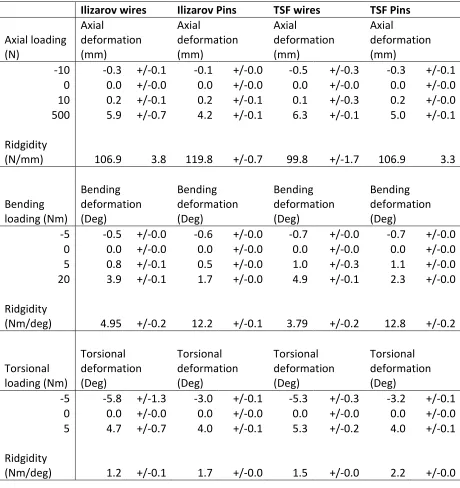
[image:25.595.73.330.300.645.2]Ilizarov wires Ilizarov Pins TSF wires TSF Pins Axial loading (N) Axial deformation (mm) Axial deformation (mm) Axial deformation (mm) Axial deformation (mm)
-10 -0.3 +/-0.1 -0.1 +/-0.0 -0.5 +/-0.3 -0.3 +/-0.1
0 0.0 +/-0.0 0.0 +/-0.0 0.0 +/-0.0 0.0 +/-0.0
10 0.2 +/-0.1 0.2 +/-0.1 0.1 +/-0.3 0.2 +/-0.0
500 5.9 +/-0.7 4.2 +/-0.1 6.3 +/-0.1 5.0 +/-0.1
Ridgidity
(N/mm) 106.9 3.8 119.8 +/-0.7 99.8 +/-1.7 106.9 3.3
Bending loading (Nm) Bending deformation (Deg) Bending deformation (Deg) Bending deformation (Deg) Bending deformation (Deg)
-5 -0.5 +/-0.0 -0.6 +/-0.0 -0.7 +/-0.0 -0.7 +/-0.0
0 0.0 +/-0.0 0.0 +/-0.0 0.0 +/-0.0 0.0 +/-0.0
5 0.8 +/-0.1 0.5 +/-0.0 1.0 +/-0.3 1.1 +/-0.0
20 3.9 +/-0.1 1.7 +/-0.0 4.9 +/-0.1 2.3 +/-0.0
Ridgidity
(Nm/deg) 4.95 +/-0.2 12.2 +/-0.1 3.79 +/-0.2 12.8 +/-0.2
Torsional loading (Nm) Torsional deformation (Deg) Torsional deformation (Deg) Torsional deformation (Deg) Torsional deformation (Deg)
-5 -5.8 +/-1.3 -3.0 +/-0.1 -5.3 +/-0.3 -3.2 +/-0.1
0 0.0 +/-0.0 0.0 +/-0.0 0.0 +/-0.0 0.0 +/-0.0
5 4.7 +/-0.7 4.0 +/-0.1 5.3 +/-0.2 4.0 +/-0.1
Ridgidity
[image:26.595.68.528.71.559.2](Nm/deg) 1.2 +/-0.1 1.7 +/-0.0 1.5 +/-0.0 2.2 +/-0.0
Table 1.
Figure 3. Load deformation plots for testing of frame elements alone under axial, bending
[image:27.595.76.520.306.536.2]and torsional loads.
Figure 4. Box and whisker plot of stiffness data for Ilizarov and TSF; frame elements alone, fine-wire
& half-pin constructs; under axial, bending and torsional loading. Boxes represent 25th – 75th
percentiles with whiskers from minimum to maximum values. The line through the middle of the box
Figure 5. Load-deformation plots for testing of bone-frame constructs under axial, bending