City, University of London Institutional Repository
Citation:
Fu, F. ORCID: 0000-0002-9176-8159 and Parke, G. A. (2018). Assessment of the Progressive Collapse Resistance of Double-layer Grid Space Structures using implicit and explicit solvers. International Journal of Steel Structures, doi: 10.1007/s13296-018-0030-1This is the published version of the paper.
This version of the publication may differ from the final published
version.
Permanent repository link:
http://openaccess.city.ac.uk/19535/Link to published version:
http://dx.doi.org/10.1007/s13296-018-0030-1Copyright and reuse: City Research Online aims to make research
outputs of City, University of London available to a wider audience.
Copyright and Moral Rights remain with the author(s) and/or copyright
holders. URLs from City Research Online may be freely distributed and
linked to.
City Research Online: http://openaccess.city.ac.uk/ [email protected]
https://doi.org/10.1007/s13296-018-0030-1
Assessment of the Progressive Collapse Resistance of Double‑Layer
Grid Space Structures Using Implicit and Explicit Methods
F. Fu1 · G. A. R. Parke2
Received: 28 March 2016 / Accepted: 21 January 2018 © The Author(s) 2018
Abstract
A double-layer grid space structure is a conventional long span structure used where large column-free areas are required. Due to its’ large indeterminacy and the redundancy of its structural configuration, it is normally considered in design prac-tice, that progressive collapse will not be triggered when the loss of an individual member occurs. However, research and several prior accidents have shown that progressive collapse could occur following the loss of some critical members when the structures are subject to abnormal loading such as heavy snow. To investigate the structural behavior of this type of structure, a 3D finite element model of a double-layer space structure grid was built by the authors, several collapse scenarios have been investigated using an implicit method which follows the alternative path method defined in GSA. In addition, case studies have been made using the explicit method which is to simulate the whole process of the structural collapse. In the analysis, different members failure or support collapses were studied. The response of the structure was investigated and the correspondent potential of progressive collapse was discussed in detail. Methods to mitigate the progressive collapse of this type of space structure have also been recommended.
Keywords Double-layer grid · Progressive collapse · Explicit analysis · Implicit analysis · Alternative path method
1 Introduction
After the event of the 11th September 2001, more and more research has been refocused on the causes of progressive collapse in building structures and possible mitigating meth-ods. There are also design procedures in the UK and the US aimed at mitigating the potential for progressive collapse of structures. In the U.K., the British Building Regulations
(2004) and BS5950 (2001) has led with requirements for the
avoidance of disproportionate collapse. In the United States,
the ASCE 7 (2005) gives a clear definition of “progressive
collapse”. The Department of Defense (DoD) (2005) and
the General Services Administration (GSA) (2003) provide
detailed information and guidelines on methodologies pro-posed to resist progressive collapse of building structures.
Both guidelines employ the alternate path method (APM). The APM is a threat independent methodology, meaning that it does not consider the type of triggering event, but rather considers the building system response after the triggering event has destroyed critical structural members. If one com-ponent fails, alternate load paths are available for the gravity forces and a general collapse does not occur. The methodol-ogy is generally applied in the context of a ‘missing column’ scenario to assess the potential for progressive collapse and used to check if a building can successfully cope with the
loss of a critical member. The references FEMA (2002) and
NIST (2005) also provide some general design
recommenda-tions, which require steel-framed structural systems to have enough redundancy and resilience, such that alternative load paths and additional capacity are provided for by redistribut-ing gravity loads when structural damage occurs.
However, most of the research and design guidance so far has concentrated on assessing the collapse behavior of multi-storey buildings. Little work has been undertaken investigating the response of space structures. A double-layer grid is one of the conventional types of space struc-tures which are usually three-dimensional pin-jointed truss structures used to provide large, clear spans, free * F. Fu
1 Department of Civil Engineering, School of Mathematics,
Computer Science and Engineering, City University London, Northampton Square, London EC1V 0HB, UK
2 Department of Civil and Environmental Engineering,
of intermediate supports. Because of their large degree of indeterminacy, they are often assumed to have suffi-cient redundancy such that the loss of one member would cause force redistributions that can be accommodated by the remaining structure. Therefore, in design practice, it is normally considered that the progressive collapse of these structural types will not be triggered when the loss of members occurs. However, the collapse of several promi-nent structures in the past has shown that progressive col-lapse of these types of structure can occur following the loss of some of the critical members such as happened in the Hartford Coliseum collapse. In the research
pre-sented by Murtha-Smith (1998), the author performed an
analysis on hypothetical space trusses and showed that progressive collapse could occur following the loss of just one of several potentially critical members when the structures were subject to full service loading. However, when the structures were evaluated using the American National Standard ANSI A58.1-1982, the structures were found to survive with a small margin of safety.
Bland-ford (1996) performed the progressive failure analysis of
inelastic space truss structures. Richard Liew et al. (1997)
discussed the advanced analysis methods appropriate for
spatial structure. Kato et al. (1998) discussed the collapse
of semi-rigidly jointed reticulated domes with initial
geo-metric imperfections. Malla et al. (2011) proposed the
methodology suitable for the dynamic analysis of the
pro-gressive failure of truss structures. Fang and Zhao (2011)
performed the simulation of the progressive collapse together with a study of suitable methods useful for resist-ing progressive collapse of spatial grid structures based on analysis using ANSYS and LS-DYNA. Sheidaii and
Gholizadeh (2006) also investigated the collapse behavior
of double-layer space trusses using neural networks.
Shek-astehband et al. (2011) also performed sensitivity analysis
of Tensegrity systems due to sudden member loss. Although a considerable amount of research has been undertaken to investigate this problem as summarized above, the accurate behavior of double-layer grid space structures under member loss is still not quite clear. In addition, there is still no clear guidance for the design of space structure against progressive collapse. Therefore, further investiga-tion needs to be conducted. In this paper, using the general
purpose program ABAUQS (2010), a 3D finite element
model of a double-layer grid space structure was built by the authors. Using this model, analysis using both the implicit
and explicit solvers available in ABAQUS (2010) has been
performed. Different member loss scenarios were studied in detail. The response of the structure and the potential of progressive collapse of this type of structure have been discussed in detail. Methods to mitigate the progressive collapse of these types of space structure have also been recommended.
2 Prototype Structure and Modelling
Techniques
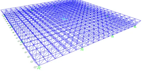
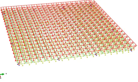
As shown in Fig. 1, a three-dimensional finite element
model has been created using the ABAQUS (2010)
analy-sis software. The structure studied is a conventional square grid 27 m long each side. The structure is composed of 324 square pyramids. These systems are sometimes formed by continuous top and bottom cords with pinned diagonal struts forming the web members in the structure. However, the normal construction of these structural types is to use individual tubular members, spanning from node to node for the top and bottom chords and additional tubular mem-bers for the diagonal web memmem-bers. All of the memmem-bers are generally considered to be pinned. However, depend-ing on the node connections the effective length of the top chord compression members is sometimes taken as less than one. The height of the grid is 1.5 m. The whole struc-ture is vertically supported at selected perimeters nodes in
the locations shown in Fig. 1. The support-to-support span
was 9 m giving a span-to-depth ratio of 6. The truss was designed for a single load case of uniformly distributed 1.4
Dead load + 1.6 Live load (the latter taken as 1.0 kN/m2)
applied through the upper chord joints. This is the design
load combination required in BS5950 (2001), which is
often used for steel design in the U.K. The conventional design under normal loading conditions was performed
in SAP2000 (2000), using iterative elastic analysis and
design modifications to make sure no member was over-stressed and that no overall buckling of the structural members were observed. To simplify the analysis, in the model, CHHF 60.3 × 5 which are 60 mm diameter pipe section with a 5 mm wall thickness were chosen for all the members. The yield stress of the chosen steel was 355 N/
mm2 with the tensile capacity of each structural member
being 308 kN. The buckling load for the top and bottom chords are 215 kN and the buckling load for the diagonal struts is 167 kN respectively.
[image:3.595.308.543.576.695.2]In the proposed model, all of the top and bottom chord and diagonals members were modelled using *BEAM ele-ments. The material properties of all the structural steel components were modelled using an elastic–plastic material behaviour from ABAQUS incorporating material nonlinear-ity. The material will behave as a linear elastic material up to the yield stress of the material. After this stage, it exhibits strain hardening characteristics until reaching the ultimate stress. As ABAQUS assumes that the response is constant outside the range defined by the input data, the material will deform continuously until the stress is reduced below this value. The elastic part of the stress–strain curve is defined
with the *ELASTIC option, the value 2.05 × 10⁵ N/mm2
for the Young’s modulus and 0.3 for Poisson’s ratio were used. The plastic part of the stress–strain curve is defined with the *PLASTIC option. Steel grade S355 was used for all the structural steel with the ultimate strength of 490 N/
mm2. Engineering stresses and strains including the yield
and ultimate strength were obtained from BS5990 and were converted into true stresses and strains with the appropriate input format for ABAQUS.
3 Analysis Using Codified Alternative Path
Method with the Implicit Method
Using general purpose program ABAQUS, the response of the structure was assessed.
In the first part of the analysis, the implicit solver in ABAQUS was used.
There is no clear guidance in particular on how to approach progressive collapse analysis of double-layer grid structures. Therefore, the alternative path method (APM) which was suggested by the American design code DOD
(2005) and GSA (2003) was applied here to perform the
pro-gressive collapse checking of the space grid. This codified methodology was to check the potential of the collapse of a building through the removal of certain structural members and checking the response of the remaining structural mem-bers to assess whether the collapse of the structure will be triggered. This method is event independent, which means, it does not assess the cause of the structural member loss, but the capacity of the remaining structure after the structural members are destroyed. Hence, the ability of the structure under sudden member loss can be assessed using a nonlinear dynamic analysis method with the 3-D finite element tech-nique. In this paper, 3D Finite Element program Abaqus was used to perform the progressive collapse analysis. Implicit solver was used in this analysis the response of the structure should be checked under the 1.0 dead loads (which are the self-weight of the structure) + 0.25 of the live load (which
is 1 kN/m2) as it is required for nonlinear dynamic analysis
with the acceptance criteria outlined in Table 2.1 of the GSA
guidelines (2005). In this particular analysis, to make the
analysis more conservative, the full live load was used, so the load combination used in the analysis is 1.0 Dead + 1.0 Live. A damping value of 3% was used in the dynamic anal-ysis. The members to be removed were forcibly removed by instantaneously deleting them, and the subsequent response of each braced frame was then investigated. The maximum forces, displacements and rotations for each of the mem-bers or connections involved in the scenario were recorded. The analysis was divided into two steps; in the first step the static load such as the dead and live loads were imposed; the second step was the dynamic procedure where the structural members were instantaneously removed. The time history of both the static step and the dynamic step was recorded for appraisal.
3.1 Frame Buckling Analysis
In the simulation, the Buckling analysis for each structural member is performed using the Frame Buckling Command available in ABAQUS for pipe cross-section frame ele-ments. In compression, the buckling strut response models in ABAQUS can simulate the highly nonlinear buckling damage of slender members when loaded monotonically or cyclically. The buckling strut envelope is derived from experiments with pipe-like members. The buckling loading
Pcr , was determined with the ISO (International
Organiza-tion for StandardizaOrganiza-tion) equaOrganiza-tion, as described below. The ISO equation was used to predict the onset of buck-ling in slender members with pipe-like cross-sections. All quantities with dimensions have dimensions of stress.
where I is the buckling stress, fc is a function of the axial
compressive stress, fb1, fb2 is the maximum bending stresses
about the local 1 and 2 axes, and, Fc is a characteristic axial
compressive stress, Fb is a characteristic bending stress, cm1
and cm2 are reduction factors corresponding to the
cross-section directions 1 and 2, Fe1 and Fe2 are the Euler buckling
stresses corresponding to the 1- and 2-directions. The ISO equation states that buckling does not occur as long as:
ABAQUS can switch between a standard frame element response and a buckling strut response and the one-time-only switch to buckling strut response occurs when
However, as it is shown in Fig. 2, the limitation of this
method is that it cannot capture the dynamic response when I(fc, fb1, fb2) =
fc
Fc+
1 Fb � � � � � �⎡⎢⎢ ⎣ cm1fb1
1− fc
Fe1 ⎤ ⎥ ⎥ ⎦ 2 + ⎡ ⎢ ⎢ ⎣
cm1fb1
1− fc
Fe1 ⎤ ⎥ ⎥ ⎦ 2
I(fc, fb1, fb2) < 1.0
using the member removal method recomanded by GSA
(2003). Therefore, in the removal analysis, a two-stage
anal-ysis is performed, in the first stage, the analanal-ysis is first per-formed using the frame buckling analysis to check whether any member bucking occurs, if member buckling occurs, that member can be removed from the model. In the second stage, the normal column removal analysis is performed, therefore, the dynamic response of the double layer grid can be captured.
3.2 Member Removal Analysis Cases
Based on GSA guidelines (2005), the APM which utilizes
the column removal method was implement in this implicit analysis and several member removal scenarios were inves-tigated, the results of which are shown in the following sec-tions. The detailed modeling techniques for removal
analy-sis please refer to Fu (2009).
3.2.1 Removal of a Square Pyramid at the Centre of the Grid
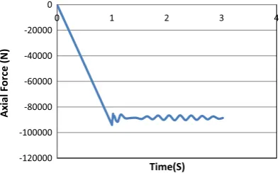
In the first analysis, one web member which was at the center of the grid was removed. However, no obvious dynamic response was observed therefore, rather than just one web member being removed, all of the web members in one square pyramid located at the center of the struc-ture were removed. It should be noted that the first second is the static step, the static load (live + dead) was applied
in this analysis step as it shown in Fig. 3. In this step, the
axial force increases from 0 to the maximum force. After the first second, the dynamic procedure started, whereupon the
structural members were removed. From Fig. 4, which is the
contour of the axial force in the remaining structure, it can be seen that the maximum tensile force observed is 101 kN and the maximum compressive force observed is 137 kN. As the tensile capacity of each structural member is 308 kN and the buckling load for the top and bottom chords is 215 kN
and the buckling load for the diagonal struts is 167 kN respectively, so this indicated that no further member fail-ure occurred after the removal of the square central pyramid. The frame buckling analysis also shows no member bucking
was observed. Figures 5 and 6 show the response of the axial
force in the structural members located close to the removed centre members. It can be observed that a dynamic response was observed for each member. However, the axial forces are still within the axial capacity of each member.
3.2.2 Corner Support Failure
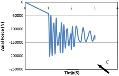
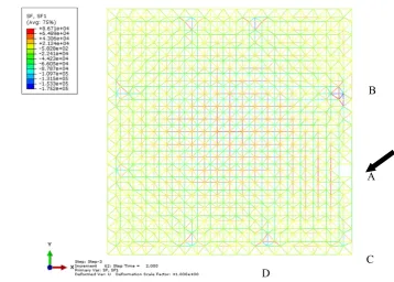
In reality, the support members are more vulnerable to dam-age than other members especially if the structure is sub-jected to earthquake induced ground displacements. Hence, in the next appraisal, support C located at the corner (the
position is shown in Fig. 7) was removed. Figure 7 is the
contour of the axial forces in each member for this particular scenario. It can be seen that after the removal of support C, some structural members close to adjacent support B and C become overloaded as most of the loads were redistributed
into these supports. Figures 8, 9 and 10 shows the response
of the axial force in the structural members near to support B. It can be seen that, after the removal of the support C, the bottom chord and the diagonal strut bucked as the axial force exceeded the buckling capacity for these members.
3.2.3 Middle Span Support Failure
In this analysis the support in the middle of one edge at point
A (shown in Fig. 11) was removed. Figure 11 shows the
distribution of the axial force in all the structural members in the structure after the removal of support A. It can be seen that after the removal of support A, some structural members close to the adjacent support B become overloaded. This is because, most of the loads carried by support A were re-dis-tributed into the remaining support primarily those supports
-140000 -120000 -100000 -80000 -60000 -40000 -20000 0
0 0.5 1 1.5 2 2.5 3 3.5
Axial Force (N)
Time (s)
Fig. 2 Axial force after member removal using the frame bucking
[image:5.595.313.543.59.196.2] [image:5.595.54.286.59.189.2]at locations B and C. Figures 12 and 13 show the response of the axial force in the structural members near support B. It can be seen that, after the removal of the support, the bottom chord and diagonal struts bucked as the axial force exceeded the buckling capacity for the relevant members.
3.3 Summary
In the above analysis, using the Alternative Path approach, several analyses have been undertaken to model different scenarios with either structural chord or web members removed or support members removed. From the investiga-tion it can be seen that if space grid structures are designed under the current design guidance with the normal live load, removal of certain selected structural members is unlikely to trigger collapse of the whole structure. This is a result of the large redundancy designed into the structure where the structure can accommodate the loss of selected failed mem-bers. However, great attention needs to be paid to support failures, because when a support fails the load will be redis-tributed to the adjacent supports which are likely to cause further member failures and trigger progressive collapse.
4 Investigation into the Failure Mode Using
the Explicit Method
In Sect. 3.1, it can be seen that for the particular double layer
square-on-square grid investigated it is more vulnerable to support failure than the structural failure of central mem-bers. Therefore, it is worthwhile to further investigate the
Fig. 4 Axial force distribu-tion in the structure after the removal of the center pyramid
C D
A B
-2000 0 2000 4000 6000 8000 10000 12000 14000
0 1 2 3 4
Axial Force (N)
Time(S)
Fig. 5 Axial force in the bottom chord near the removed central
pyra-mid
-120000 -100000 -80000 -60000 -40000 -20000 0
0 1 2 3 4
Axial Force (N)
Time(S)
[image:6.595.200.544.53.299.2] [image:6.595.72.270.521.643.2]potential for progressive collapse of the structure under sup-port failure conditions. However, as it has been explained, the Alternative Path Approach is event independent, which means it does not care the causes of the member loss. In addition, the implicit solver is hard to simulate the spread of failure and determine the failure mode of the structure. To clearly investigate the collapse mechanism of the structure, the explicit solver was used in this part of the analysis.
Abaqus/Explicit offers one additional element failure model suitable only for high-strain-rate dynamic problems which is driven by plastic yielding and can be used to limit the subsequent load-carrying capacity of an element (up to the point of removing the element) once a yield stress limit is reached. The model is used in conjunction with the Mises
Fig. 7 Axial force distribution in each member after support C removed
A B
C
D
-250000 -200000 -150000 -100000 -50000 0
0 1 2 3 4
Axial Force (N)
Time(S)
C
D
Fig. 8 Axial force in a bottom chord member near to the removed
support C
0 20000 40000 60000 80000 100000 120000 140000 160000
0 0.5 1 1.5 2 2.5 3 3.5
Axial Force (N)
Time(S)
Fig. 9 Axial force in top chord member near to the removed support
C
-180000 -160000 -140000 -120000 -100000 -80000 -60000 -40000 -20000 0
0 0.5 1 1.5 2 2.5 3 3.5
Axial Force (N)
Time(S)
[image:7.595.120.536.51.501.2] [image:7.595.71.270.363.490.2] [image:7.595.70.272.560.681.2]plasticity models or the Johnson–Cook plasticity models to define the failure of the material. The model is based on the value of the equivalent plastic strain at element integration points. Failure is assumed to occur when the damage
param-eter ω exceeds 1; ω is defined as:
where 𝜀̄pl
0 is any initial value of the equivalent plastic strain,
and is assumed to depend on the plastic strain rate. Δ ̄𝜀pl
0 is
an increment of the equivalent plastic strain, a dimensionless pressure–deviatoric stress ratio, p/q (where p is the pressure stress and q is the Mises stress); temperature; and
pre-defined field variables. 𝜀̄pl
f is the strain at failure.
The above summation is performed over all increments in the analysis. When the failure criterion is met at an integra-tion point, all the stress components will be set to zero and that material point fails. By default, if all of the material points at any one section of an element fail, the element is removed from the mesh. Using this function, the progress of the structural failure can be modelled.
The purpose of this analysis is to find out the global fail-ure mechanisms and the progressive collapse procedfail-ures associated with these structures. For all the members sec-tion used, relatively thick tubular walls were chosen, there-fore, the structural member are less prone to buckling fail-ure. And also in the real design, a sufficient wall thickness would be chosen to avoid global buckling, and due to the redundancy and the depth of the double layer grid structures,
ω =
̄ 𝜀pl
0 +
∑
Δ ̄𝜀pl
̄ 𝜀pl
f
Fig. 11 Axial force distribu-tion in the structure after the removal of support A
A B
D C
-100000 -90000 -80000 -70000 -60000 -50000 -40000 -30000 -20000 -10000 0
0 1 2 3 4
Axial Force (N)
Time(S)
Fig. 12 Axial force in the top chord member near support B
-250000 -200000 -150000 -100000 -50000 0
0 0.5 1 1.5 2 2.5 3 3.5
Axial Force (N)
Time(S)
[image:8.595.184.543.51.307.2] [image:8.595.71.270.334.461.2] [image:8.595.69.270.522.643.2]local snap through bucking or even the global buckling is not likely to occur. In contrast, single layer space frames exhibit greater sensitivity to buckling than double-layer structures, therefore, the failure model is also applicable here for the analysis.
4.1 Middle Span Support Failure: With Normal Live Load
Similar to the analysis described in Section 3.2.3, in this
subsequent appraisal the support in the middle of one side at
point A (shown in Fig. 14) was removed. The same normal
live load as that used in Section 3.2.3 was applied. However,
for this appraisal the explicit solver available in ABAQUS
was used. Figure 14 shows the structure at the early stage
when the support at point A has been removed. Figure 15
shows the structure at the final stage. No progressive
col-lapse is observed. It can also be seen that, from Figs. 14
and 15, the maximum Von Mises stress of the structural
members are lower than the yield stress of the steel material
which is 355 N/mm2, therefore, no collapse was triggered.
From the deformed shape shown in Fig. 15 it is evident that
the whole structure has deformed mainly along the line
between supports at A and A′ and supports at D and D′.
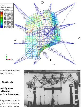
4.2 Middle Span Support Failure: With Abnormal Live Load
In order to understand the failure mechanism of the space grid, in this analysis, support A was also removed, how-ever, the live load was continuly increased until progressive collapse was observed. The value of the live load imposed
was six times greater than the load used in Sect. 3.2.1. This
was to simulate an abnormal live load condition such as a
very heavy snow load. Figure 16 shows the structure at the
early stage when the support A has been removed. It shows that progressive collapse has been triggered. The whole structure collapsed into several parts. The failure started and propagated first along the two lines between supports at
points A and A′ and support at points D and D′ (as shown in
Fig. 16). This indicates a typical failure mode of the
struc-ture. Consequently, strengthening the support members and
Fig. 14 Deformed shape of the space grid with the normal live load
during the early stage of support A removal
Fig. 15 Deformed shape of the
space grid with the normal live load during the final stage of support A removal
A A’
[image:9.595.54.287.218.406.2] [image:9.595.203.544.467.714.2]the structural members along these axial lines would be an effective method of mitigating progressive collapse.
5 Validation for the Numerical Methods
5.1 Validation for the Implicit Method Against the Collapse Response of Several Model
Square‑on‑Square Double‑Layer Grid Structures
In order to validate the numerical modeling aproach used in this paper, validation work, performed by the second author, used the implicit stiffness method to model the non-linear collapse behaviour of several square-on-square
double-layer grid structures (Parke 1988). In the analysis, both
the yielding of tension members and the plastic buckling of compression members were followed using a series of
linear steps. Figure 17 shows one of the test structures used
in the experimental investigation (Parke 1988). Figure 18
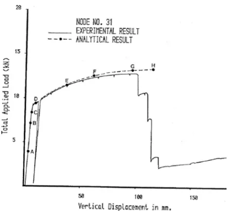
shows the analytical and experimental results obtained for the double-layer grid exhibiting extensive plastic yielding
before collapse. Figure 19 shows the analytical and
experi-mental response for the same type of double-layer grid but with both yielding tension members and plastic buckling of compression members.
Above study shows that using the implicit method is it possible to follow the non-linear collapse behavior of these structural types.
5.2 Validation for the Explicit Method Against the Snow Induced Collapse of a Double‑Layer Grid Space Structure, the Hartford Civic Center
One of the most infamous collapse incidents is the failure of the Hartford Civic Center Coliseum in 1978. Over the years three independent investigations into the complete collapse have been undertaken. The space frame construc-tion for the stadium was a double-layer grid with the top layer chord members having a cruciform cross section made up from four large angle sections. In the design of double-layer grid structures, the center lines of each member should intersect with the centre of the connecting
Fig. 16 Deformed shape of the space grid with an abnormal live load at the early stage of support A removal
D’
A
D
A’
[image:10.595.208.544.54.501.2]joint to reduce secondary bending moments. However, one of the investigation reports (Lev Zetlin Associates
1978) shows that in the case of the Hartford Civic
Cent-er’s frame, the top chords intersected at one point and the diagonals at another which caused bending stresses in the members. In addition to this, lateral bracing of the top chords was met through diagonals in the interior of the frame, but along the edges there was no means to prevent
out-of-plane bending (Lev Zetlin Associates 1978).
A faulty weld connecting the scoreboard to the roof was also noticed. A massive amount of energy would have been caused by the volatile weld release, possibly causing
the entire structure to collapse (Feld and Carper 1997). It
was also noticed that once the roof truss was in place, the construction manager altered the roof cladding material, increasing the dead load by 20% and hence the dead loads were substantially underestimated in the initial structural
analysis (Feld and Carper 1997).
Careful examination of the collapsed roof shown in
Fig. 20, show two distinct lines of failed top chord
com-pression members indicating that once one of the top chord edge members failed, the adjacent compression members were unable to carry the loads shed to them by the failed member and as a result failure progressed rapidly across the entire structure. This similar failure pattern can be observed
in Figs. 14, 15 and 16. This indicates the proposed
model-ling method can accurate simulate the failure mode of the space structure.
Fig. 18 The analytical and experimental results obtained for the double-layer grid exhibiting extensive plastic yielding of the tension members before collapse (tested under displacement control)
Fig. 19 The analytical and experimental response of the double-layer grid with both yielding tension members and plastic buckling of com-pression members (tested under displacement control)
[image:11.595.53.288.53.270.2] [image:11.595.53.285.346.528.2] [image:11.595.308.542.376.684.2]6 Comparison of the Two Analysis Methods
From above analyses, it can be seen that, both implicit and explicit analyses can be used to judge the potential for the collapse of the structure. The implicit method uses the codi-fied analysis methods which are based on the GSA
guide-lines (2003). This method used the so called APM. In the
analysis the structure members are removed to investigate the collapse potential of the structure. It is easy and straight forward, the analysis process is much quicker and takes less computational time compared to using the explicit method. However, it cannot simulate the overall collapse process of the structure.
Unlike the implicit method, using the explicit method simulating the whole collapse process is possible, however, it requires more computational time which means it is not easier to use in general practice. However, it can provide an accurate representation of the collapse process of the structure.
7 Conclusions
In this paper, models were made using the general purpose
program ABAUQS (2010), to simulate the collapse
behav-iour of a double-layer grid space structure. The simulation was undertaken using both the implicit and explicit solv-ers within ABAQUS. Different removal scenarios were appraised notably on the removal of internal central mem-bers and also supports member. Below are the main findings emanating from the investigation:
1. Due to the high redundancy of the structure, for a space grid supported around the boundary, designed under current design guidance, supporting a normal live load, removal of several selected central structural members is unlikely to trigger the collapse of the whole structure. 2. For double-layer grid structures not fully supported
around the boundary when a boundary support fails, the load will be redistributed to the adjacent supports which may cause further member failures and triggering the collapse of the whole structure.
3. In the event of progressive collapse due to the failure of one of the supports, the failure is propagated along the axial lines drawn between the failed support and the two opposite supports. Therefore, strengthening all of the support members and possibly also the members along the grid lines running across the structure connecting the relevant pairs of supports would be an effective method of mitigating progressive collapse.
4. Under the abnormal live load condition such as a very heavy snow load a progressive collapse of the structure
can be triggered, therefore, a sufficient design margin should be considered.
5. Though the explicit method can simulate the whole col-lapse process, the implicit codified method is simple and straight forward, therefore can be recommended for practical engineers to use.
Open Access This article is distributed under the terms of the
Crea-tive Commons Attribution 4.0 International License (http://creat iveco mmons .org/licen ses/by/4.0/), which permits unrestricted use, distribu-tion, and reproduction in any medium, provided you give appropriate credit to the original author(s) and the source, provide a link to the Creative Commons license, and indicate if changes were made.
References
ABAQUS Theory Manual. (2010). Version 6.10. Pawtucket, RI: Hib-bitt, Karlsson and Sorensen, Inc.
ASCE. SEI/ASCE 7-05. (2005). Minimum design loads for buildings and other structures. Washington, DC: American Society of Civil Engineers.
Blandford, G. E. (1996). Progressive failure analysis of inelastic space truss structures. Computers & Structures,58(5), 981–990. British Standards Institution. BS 5950. (2001). Structural use of
steel-work in buildings, part 1: Code of practice for design—Rolled and welded sections. London, UK: British Standards Institution. CSI, SAP2000.
Fang, Y. L., & Zhao, Z. Z. (2011). Numerical simulation of progressive collapse and study of resisting progressive collapse of spatial grid structures based on ANSYS/LS-DYNA.3. Advanced Materials Research,243–249, 6202–6205.
Federal Emergency Management Agency (FEMA). (2002). FEMA 403, world trade center building performance study: Data collection, preliminary observations, and recommendations. Washington, DC: Federal Emergency Management Agency (FEMA). Feld, J., & Carper, K. (1997). Construction failure. New York: Wiley. Fu, F. (2009). Progressive collapse analysis of high-rise building with 3-D finite element modelling method. Journal of Constructional Steel Research,65(6), 1269–1278.
GSA. (2003). Progressive collapse analysis and design guidelines for new federal office buildings and major modernization projects. Washington, DC: The U.S. General Services Administration. Kato, S., Mutoh, I., & Shomura, M. (1998). Collapse of semi-rigidly
jointed reticulated domes with initial geometric imperfections. Journal of Constructional Steel Research,48(2–3), 145–168. Lev Zetlin Associates. (1978). Report of the engineering investigation
concerning the causes of the collapse of the Hartford Coliseum space truss roof on January 18, 1978, June 12, 1978.
Malla, R. B., Agarwal, P., & Ahmad, R. (2011). Dynamic analysis methodology for progressive failure of truss structures, consider-ing inelastic post-bucklconsider-ing cyclic member behavior. Engineering Structures,33, 1503–1513.
Murtha-Smith, E. (1998). Alternate path analysis of space trusses for progressive collapse. Journal of Structural Engineering, ASCE, 114(9), 1978–1999.
Office of the Deputy Prime Minister. (2004). The building regula-tions 2000, part A, schedule 1: A3, Disproportionate collapse. London, UK: Approved Document A (Structure) 2004 Edition incorporating 2004, 2010, and 2013 amendments. Department for Communities and Local Government.
Parke, G. A. R. (1988). The behaviour of space trusses incorporating novel compression members. PhD Thesis, University of Surrey, 1988.
Richard Liew, J. Y., Punniyakotty, N. M., & Shanmugam, N. E. (1997). Advanced analysis and design of spatial structures. Journal of Constructional Steel Research,42(1), 21–48.
Sheidaii, M. R., & Gholizadeh, S. (2006) An investigation into the collapse behavior of double-layer space truss using neural net-works. In 7th international congress on civil engineering. Tarbiat Modarres University, Tehran.
Shekastehband, B., Abedi, K., & Chenaghlou, M. R. (2011). Sensitiv-ity analysis of TensegrSensitiv-ity systems due to member loss. Journal of Constructional Steel Research,67, 1325–1340.