City, University of London Institutional Repository
Citation
:
Ruiz, R., Taflanidis, A., Giaralis, A. ORCID: 0000-0002-2952-1171 and Lopez-Garcia, D. (2018). Multi-criteria optimization of seismic protective devices utilizing lifecycle performance objectives and application to the design of the tuned mass damper inerter (TMDI) for buildings in Chile. Paper presented at the 16th European Conference on Earthquake Engineering- 16ECEE, 18 - 21 June 2018, Thessaloniki, Greece.This is the accepted version of the paper.
This version of the publication may differ from the final published
version.
Permanent repository link:
http://openaccess.city.ac.uk/21914/Link to published version
:
Copyright and reuse:
City Research Online aims to make research
outputs of City, University of London available to a wider audience.
Copyright and Moral Rights remain with the author(s) and/or copyright
holders. URLs from City Research Online may be freely distributed and
linked to.
City Research Online: http://openaccess.city.ac.uk/ [email protected]
MULTI-CRITERIA OPTIMIZATION OF SEISMIC PROTECTIVE
DEVICES UTILIZING LIFECYCLE PERFORMANCE OBJECTIVES
AND APPLICATION TO THE DESIGN OF THE TUNED MASS
DAMPER INERTER (TMDI) FOR BUILDINGS IN CHILE
Rafael RUIZ1, Alexandros TAFLANIDIS2, Agathoklis GIARALIS3, Diego LOPEZ-GARCIA4
ABSTRACT
A probabilistic framework for the cost-effective design of supplemental seismic protective devices considering multiple criteria related to their life-cycle performance is reviewed in this contribution. The framework relies on time-history analysis for describing structural behavior, on an assembly-based vulnerability approach for quantifying earthquake losses, and on characterization of the earthquake hazard through stochastic ground motion modeling. Emphasis is placed on application to the design of the tuned mass-damper inerter (TMDI) which if properly tuned can outperform the classical tuned mass damper for the same attached mass due to the presence of the inerter. The latter is a two-terminal device developing a resisting force proportional to the relative acceleration of its terminals by the “inertance” constant. In the herein considered multi-criteria design framework, the life-cycle cost of the TMDI equipped structure is the primary objective composed of the upfront TMDI cost and the anticipated seismic losses over the lifetime of the structure. For enhanced decision support, two additional objectives, namely the repair cost and the inerter force, having specific probability of exceedance over the lifetime of the structure are examined. The repair cost incorporates risk-averse attitudes into the design process, while the inerter force incorporates practical constraints to the transmitted stresses from the TMDI to the host structure. A case study involving an actual 21-storey building constructed in Santiago, Chile shows that optimal TMDI configurations can accomplish simultaneous reduction of life-cycle and repair costs. However, these cost reductions come at the expense of increased inerter forces to be transferred from the TMDI to the host structure. It is further shown that connecting the inerter to lower floors provides considerable benefits across all examined performance criteria as the inerter is engaged in a more efficient way for the same inertance and attached mass ratios.
Keywords: tuned mass-damper-inerter; multi-criteria design; seismic risk; risk aversion; life-cycle performance
1. INTRODUCTION
Significant advances have been established in the last decade in seismic-risk decision management through development of assessment and design methodologies based on detailed socio-economic metrics quantifying performance, such as casualties, repair costs, and downtime (Goulet et al. 2007). In this context, life-cycle cost analysis of structures has become increasingly popular. This analysis considers the contribution of the initial (upfront) cost as well as of the expected direct and indirect losses due to future seismic events in decision making. It has motivated researchers to look into the life-cycle cost-based assessment/design of structures equipped with supplemental seismic protective devices (Shin and Singh 2014; Gidaris and Taflanidis 2015). In this regard life-cycle analysis can provide a comprehensive justification for the proposed seismic upgrades, which constitutes a necessary step for adoption of such alternative earthquake-protective measures. Consideration of
1Assistant Professor, University of Chile, Santiago, Chile, [email protected]
2Associate Professor, University of Notre Dame, Notre Dame, U.S.A, [email protected] 3Senior Lecturer, City, University of London, London, UK, [email protected]
4Associate Professor, Pontificia Universidad Católica de Chile & Researcher, National Research Center for
2
multiple, advanced criteria for quantifying seismic-risk (i.e. life-cycle performance), especially metrics related to risk-aversion principles, can provide enhanced decision support as it allows for performance evaluation across a variety of competing objectives (Gidaris et al. 2017). This contribution reviews a computationally efficient, multi-objective design framework to support this goal, focusing on an application for the design of the tuned mass damper inerter (TMDI) for buildings in Chile.
The TMDI (Marian and Giaralis 2013; Marian and Giaralis 2014) couples the tuned mass damper (TMD) with an inerter, a two-terminal mechanical device developing a resisting force proportional to the relative acceleration of its terminals (Smith 2002). The underlying constant of proportionality (“inertance”) can be orders of magnitude larger than the physical mass of the inerter. In the TMDI, the inerter increases the apparent inertial property of the TMD for a given attached (secondary) mass without increasing its weight. This is achieved by connecting the TMD mass via the inerter to a
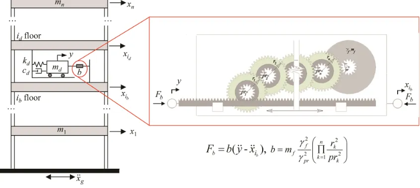
[image:3.612.97.520.379.569.2]different floor from the one that the TMD is attached to in a multi-storey primary building structure as depicted in Figure 1. In a number of studies (Marian and Giaralis 2014; Giaralis and Marian 2016; Giaralis and Taflanidis 2017; Ruiz et al. 2017) the TMDI was shown to outperform the TMD for seismic applications, especially for relatively small secondary mass. Beyond the mass amplification effect, an important aspect of the TMDI is its ability to influence the dynamics of the primary structure in a wide frequency range and not only at frequencies close to the own TMDI oscillation frequency, as is the case of the classical TMD (Giaralis and Taflanidis 2017). Another important aspect is the significant impact of the inerter topological configuration on the overall performance; it was shown by Giaralis and Taflanidis (2017) that TMDI configurations with the inerter connecting to a lower floor than the floor immediately underneath the secondary mass provide significant advantages [see also (Giaralis and Petrini 2017)]. Nevertheless, Giaralis and Taflanidis (2017) adopted stationary description for the excitation while they focused only on the TMDI performance. No consideration was given to limiting the forces exerted from to the host structure, which can be quite significant.
Figure 1. Tuned mass-damper-inerter (TMDI) equipped multi-storey frame structure and schematic representation of a rack-and-pinion flywheel-based inerter device with n gearing stages.
3
Risk quantification is accomplished through linear response history analysis, whereas the seismic hazard is described through a stochastic ground motion model that offers hazard-compatibility with ground motion prediction equations available for Chile. The main performance criterion utilized in the design optimization, representing overall direct benefits, is the life-cycle cost of the system, composed of the upfront TMDI cost and the anticipated seismic losses over the lifetime of the structure. For enhanced decision support, two additional criteria are examined, both represented though some response characteristic with specific probability of exceedance over the lifetime of the structure (therefore corresponding to design events with specific annual rate of exceedance). One such characteristic corresponds to the repair cost, and incorporates risk-averse attitudes into the design process, whereas the other corresponds to the inerter force, which incorporates practical constraints for the force transfer between TMDI and the supporting structure.
The remaining of the paper is organized as follows. In the next Section the equations of motion of the TMDI are reviewed, followed (Section 3) by the probabilistic framework for the performance quantification. In Section 4 the multi-objective design is discussed, including numerical details for its implementation. Section 5 furnishes pertinent numerical data for a real-life existing building in Santiago, Chile to demonstrate the benefits of the TMDI (over the TMD) within the proposed design framework, while Section 6 summarizes conclusions.
2. EQUATIONS OF MOTION OF TMDI EQUIPPED MULTI-STOREY FRAME BUILDINGS
Consider the planar n-storey frame building, shown in Figure 1, whose oscillatory motion due to a ground acceleration xg is to be suppressed (primary structure). Linear structural behavior is assumed here since it has been shown that for the Chilean region modern design/construction practices results in structures that demonstrate practically linear behavior even under strong excitations (EERI Special Earthquake Report 2010). The TMDI consists of a classical TMD located at the id-th floor of the
primary structure comprising the secondary mass md attached to the structure via a linear spring of
stiffness kd and a linear dashpot of damping coefficient cd. The TMD mass is linked to the ib-th floor
by an inerter with inertance b. Let n
s
x be the vector of floor displacements of the primary structure
relative to the ground and xg be the ground acceleration. Denote by n
d
R the TMDlocation
vector specifying the floor the TMD is attached to (i.e., vector of zeros with a single one in its id
entry), and by n
b
R be the inerterlocation vector specifying the floor the inerter is connected to (i.e., vector of zeros with a single one in its ib entry). Let, also, y be the displacement of the TMD
mass relative to the id floor and define the connectivity vector by Rc=Rd-Rb. Then, the resisting inerter
force, denoted by Fb in Figure 1, is equal to F tb( )b y t
( )R xc s ( )t
and the coupled equations ofmotion for the TMDI equipped primary structure in Figure 1 modeled as lumped-mass damped multi degree-of-freedom (MDOF) system are written as
( )
( ) ( ) s ( )
( )T T T
s dmd d cb c s t md d b c y t s s t s t s dmd d s gx t
M R R R R x R R C x K x M R R R (1)
( ) ( ) T T ( ) ( ) ( ) T ( )
d d d c s d d d d s g
m b y t m R bR x t c y t k y t m R R x t , (2)
where n nx
s
M , n nx
s
C , and n nx
s
K are the mass, damping, and stiffness matrices of the
primary structure, respectively, and n
s
R is the earthquake influence coefficient vector (vector of ones). Note that in deriving Equations (1) and (2) the inerter is taken as weightless, and, therefore, it does not attract any seismic lateral force (Marian and Giaralis 2014). This consideration is justified by referring to a typical flywheel-based inerter implementation shown in the inlet of Figure 1 in which the inertance b is proportional to the product of the square of the gearing ratios, rk/prk, k= 1,2,…n, where n is the number of gears used to drive a flywheel with mass mf and radius γf. Adding a single gear
increases b significantly with negligible increase of its weight [see also (Smith 2002)]. Detailed discussion on practically achievable values of b for large-scale building structures may be found in (Giaralis and Petrini 2017). Equation (2) suggests that the total inertia of the TMDI is equal to (md+b).
4 1
/ ; ; ;
( ) 2( )
d d d
d d
d d d
k c b m
f
m b m b M M
, (3)
where ω1 and M are the fundamental natural frequency and the total mass of the primary structure,
respectively and ωd fdω1 represents the TMDI natural frequency.
3. QUANTIFICATION OF LIFE-CYCLE PERFORMANCE AND DESIGN CRITERIA
3.1 Risk quantification
The quantification of seismic risk follows the framework shown in Figure 2, initially discussed in (Taflanidis and Beck 2009). It relies on adopting appropriate models for the seismic excitation (hazard analysis), structural system (structural analysis) and loss evaluation (damage and loss analysis), and on assigning appropriate probability distributions to the parameters that are considered as uncertain in these different models. The latter uncertainty characterization supports ultimately the seismic risk quantification. Structural behavior is evaluated through time-history analysis and seismic consequences through an assembly-based vulnerability approach, whereas for providing an appropriate within this context description of the seismic excitation (acceleration time-histories) a site-based stochastic ground motion model is adopted. This model is established by modulating a white noise sequence through functions that address the frequency and time-domain characteristics of the excitation. The parameters of these functions are related to seismological characteristics, the moment magnitude M and the rupture distance rrup, through predictive relationships. These predictive
[image:5.612.117.502.409.639.2]relationships are optimized (Vetter et al. 2016) to provide compatibility with the regional hazard by establishing a match to ground motion prediction equations available for Chile. Details about this ground motion modeling may be found in (Ruiz et al. 2015). Once the stochastic ground motion model is optimized the adoption of probability distributions for the seismological parameters facilitates a comprehensive probabilistic description of the seismic hazard (Taflanidis and Beck 2009).
Figure 2. Schematic for risk quantification framework
In this context, let θ lying in Θ n, be the augmented vector of continuous uncertain model
5
motion model. Also, let the vector of controllable parameters for the TMDI referred to herein as
design variables, bex X nx, where X denotes the admissible design space. Ultimately x includes
the mass md(or mass ratio μ), the inertance b (or inertance ratioβ),the stiffness kd (or frequency ratio fd), and the damping coefficient cd (or damping ratio ζd). For a specific design configurationx,the risk
consequence measure describing the favorability of the response from a decision-theoretic viewpoint is given by hr(θ,x). Each consequence measure hr(.) is related to (i) the earthquake performance/losses
that can be calculated based on the estimated response of the structure z (performance given that some seismic event has occurred), as well as to (ii) assumptions made about the rate of occurrence of earthquakes (incorporation of the probability of seismic events occurring). Seismic risk, Hr(x), is then
described through the expected value of the risk-consequence measure, given by the generic multi-dimensional integral
( ) ( , ) ( )
r Θ r
H x
h θ x pθ θd . (4)Through different selection of the risk consequence measure different risk quantifications can be addressed within this framework, supporting the estimation of all necessary design metrics.
3.2 Design metrics quantification
The main metric utilized in the design formulation is the total life-cycle cost C(x)=Ci(x)+Cl(x),
provided by adding the initial (upfront) cost Ci(x), which is a function of the TMDI characteristics, and
the cost due to earthquake losses over the life-cycle of the structure Cl(x). For a Poisson assumption of
earthquake occurrence, as considered later in the case study, the present value Cl(x) of expected future
seismic losses is given by the integral of Equation (4) with associated risk consequence measure
( , ) ( , ) (1 r td life) / ( )
r r life d life
h θ x C θ xvt e r t , (5)
where rd is the discount rate, tlife is the life cycle considered and Cr(θ,x) is the cost given the
occurrence of an earthquake event. For estimating the latter an assembly-based vulnerability approach is adopted. The components of the structure are grouped into damageable assemblies, different damage states are designated to each assembly and a fragility function (quantifying the probability that a component has reached or exceeded its damage state) and repair cost estimates are established for each damage state. The former is conditional on some engineering demand parameter (EDP), which is related to peak characteristics for the structural response (e.g. peak interstory drift, peak floor acceleration, etc.). Combination of the fragility and cost information provides then Cr(θ,x).
Consideration of only the life-cycle cost as performance objective facilitates what is commonly referenced as “risk-neutral” design, which assumes that preference is assessed only through quantities that can be monetized. Frequently nontechnical factors, such as social risk perceptions, need to be taken into account that lead to more conservative designs (risk aversion), since risk-neutral design does not explicitly address the unlikely but potentially devastating losses that lie on the tail of the losses/consequence distribution (Gidaris et al. 2017). This is addressed in the design framework by considering the repair cost with specific probability of exceedance over the life-cycle of the structure Based on the Poisson assumption of seismic events, the probability of the repair cost Crexceeding a
targeted threshold Cthresh(x) over the considered lifetime of the structure is
[C ( )| , seismic event]
[C ( ) | , ] 1 expt v Plife r Cthresh
r thresh life
P C t x x
x x , (6)
where [CP rCthresh( ) | , seismic event]x x is the probability of exceeding the repair threshold given that a seismic event has occurred. The latter is given by the generic risk integral (4) with risk consequence measure hr( , )θ x IC( , )θ x corresponding to an indicator function, being one if Cr(θ, x) > Cthresh(x) and
6
A third metric is finally considered for the TMDI application to accommodate the fact that none of the above two metrics account explicitly for a potential local strengthening needed to support the transfer of forces from the TMDI to the host structure. The TMDI configuration may lead to large inerter forces in large-scale building structures (see e.g., Giaralis and Petrini 2017), and accommodation of these forces may require local strengthening of the structural elements supporting the TMDI. This could be taken into account as a component of the upfront cost Ci(x), though this requires detailed
evaluation of alternative retrofitting solutions. Instead, an approximation is established here by adopting as an additional design metric a reference inerter force, corresponding to the force for a specific design event. This is similar to the approach adopted for quantifying the reference capacity for other type of protective devices, such as fluid viscous dampers (Gidaris et al. 2017). This reference force ultimately represents the degree of seismic strengthening that will be required. The design event is quantified here by equivalently looking at the inerter force with specific probability of exceedance over the life-cycle of the structure [P FbFthresh( ) | ,x xtlife]. This probability is given by an equation similar to Equation (6), simply with risk consequence measure (used to calculate
[ b thresh( ) | , seismic event]
P F F x x ) hr( , )θ x Ii( , )θ x , being one if Fb(θ,x)>Fthresh(x) and zero if not.
4. MULTI-OBJECTIVE DESIGN
4.1 Problem formulation
The multi-criteria design is expressed ultimately as
arg min ( ) , ,
such that [ | , ]
[ | , ] ,
T *
i l thresh thresh
X
r thresh life or
b thresh life ob
C C C C F
P C C t p
P F F t p
x
x x x x x x
x x x x
(7)
where C(x) [first objective] is the life-cycle cost, Cthresh(x) [second objective] is the repair threshold
with probability of being exceeded por over the lifetime of the structure and Fthresh(x) [third objective]
is the inerter force with probability of being exceeded pob over the lifetime of the structure. This
multi-objective formulation leads ultimately to a set of points (also known as dominant designs) that lie on the boundary of the feasible objective space and they form a manifold: the Pareto front. A point belongs to the Pareto front and it is called Pareto optimal point if there is no other point that improves one objective without detriment to any other. The multi-objective problem allows for the identification of a range of TMDI configurations (Pareto optimal solutions) striking a trade-off among (i) total cost [C(x)], (ii) consequences of rare events [Cthresh(x)] and (iii) strengthening required for facilitating the
TMDI force transfer. The first objective is estimated within a life-cycle setting whereas the other two as values corresponding to a design event (specific annual rate of exceedance, defined through por and pob). The designer or decision maker (e.g. building owner) can ultimately make the final decision
among the Pareto optimal solutions, incorporating any additional considerations including architectural constraints for the TMDI implementation (accommodation of larger TMDI mass).
4.2 Computational approach for the multi-objective design problem
Optimization of Equation (7) requires different risk metrics, C(x), Cthresh(x) and Fthresh(x), whose
estimation involves calculation of a probabilistic integral of the form (4). Stochastic simulation is adopted here for this estimation: using a finite number, N, of samples of θ drawn from proposal density q(θ), an estimate for the risk integral of interest [expressed through generalized form of (4)] is:
1
1 ( )
ˆ ( ) ( , )
( )
j
N j
r j r j
p
H h
N q
θx x θ
θ , (8)
sample-7
set. The proposal density q(θ) is used to improve the efficiency of this estimation (i.e., reduce the coefficient of variation of that estimate), by focusing the computational effort on regions of the Θ
space that contribute more to the integrand of the probabilistic integral in Equation (4) -this corresponds to the concept of Importance Sampling (IS).
The design problem in Equation (7) is then solved by substituting the stochastic simulation estimates of form given by Equation (8) for the required probabilistic integrals. The existence of the prediction error (stemming from the stochastic simulation) within the optimization is addressed by adopting an exterior sampling approach (Spall 2003), utilizing the same, sufficiently large, number of samples throughout all iterations in the optimization process. That is, {θj; j=1,…,N} in Equation (8) is chosen
the same for each design configuration examined, therefore reducing the importance of the estimation error in the comparison of different design choices by creating a consistent error in these comparisons. Furthermore, for supporting an efficient optimization a kriging surrogate modeling approach was advocated in (Ruiz et al. 2015; Ruiz et al. 2017). The surrogate model is established here to provide an approximate relationship between the design selection x (input to the surrogate model) and the risk quantities needed in the optimization of Equation (7), Cthresh(x), Fthresh(x), and Cl(x) (outputs for the
surrogate model) and is developed through the following approach. A large set of design configurations for the TMDI is first established to serve as support points for the kriging, utilizing a latin hypercube sampling in X. The response of each design configuration is then evaluated through time-history analysis, and then the risk quantities Cthresh(x), Fthresh(x), and Cl(x) are calculated. Using
this information the kriging metamodel is developed. This metamodel allows a highly efficient estimation of the risk measures of interest (thousands of evaluations within minutes) and is then used within the multi-objective optimization of Equation (7), coupled with an appropriate assumption for the upfront damper cost (used to calculate the overall cost C). The multi-objective problem can be then solved through any appropriate numerical method.
5. CASE STUDY
As case study the design of a TMDI for a 21-story existing building located in Santiago, Chile is considered (Zemp et al. 2011). The building has tapered elliptical shape, length 76.2 m and average depth 20 m (varying across its length), and has already a TMD installed on its last floor along its slender axis. The same configuration is examined here.
5.1 Model and cost characteristics
Seismic events occurrence are assumed to follow a Poisson distribution and so are history independent. The uncertainty in moment magnitude M is modeled by the Gutenberg-Richter relationship truncated on the interval [Mmin, Mmax] = [5.5, 9.0], (events smaller than Mmin do not
contribute to the seismic risk) which leads to ( ) b MM ( b MM min b MM max)
M
p M b e e e and expected
number of events per year v e aMb MM min eaMb MM max. The regional seismicity factors b
M and aM are
chosen by averaging the values for the seismic zones close to Santiago based on the recommendations in (Leyton et al. 2009). This results to bM=0.8loge(10) and aM=5.65loge(10). Regarding the uncertainty
in the event location, the closest distance to the fault rupture, rrup, for the earthquake events is assumed
to follow a beta distribution in [30 250] km with median rmed=100 km and coefficient of variation
8
The discount rate is taken equal to 1.5% and the lifetime tlife is assumed to be 50 years. The repair cost
and inerter force thresholds are taken to correspond to probability po=10% over tlife. The life-cycle cost
and Cthresh for the uncontrolled structure are, respectively, $2.02x10⁶ and $1.13x10⁶. The upfront
TMDI cost is based on the attached mass. The underlying assumption is that the inerter and damper cost is by comparison negligible. This cost is approximated to be linearly related to the TMDI mass
Ci(x)=bcm (Ruiz et al. 2015) with value of bc equal to 2500 $/ton. This value is taken based on (Tse et
al. 2012), additionally considering here that implementation is unidirectional and has no smart components (purely passive application).
5.2 Design and optimization details
Three different topological configurations are examined in which the secondary mass is attached to the top floor (id=21) whereas the inerter is connected to one of the three floors below, ib=20, ib=19, ib=18,
respectively. The different topologies will be distinguished, herein, using their respective ib value. As
discussed earlier, the design vector corresponds to the inertance ratio β, the mass ratio μ, the damping ratio ζdand the frequency ratio fd. The domain for each design variable for the metamodel development
[image:9.612.127.462.449.674.2]are taken as [0 4.5] for β, [0.1 1.0]% for μ (it is assumed that greater than 1.0% mass ratios are impractical to be achieved and ratios lower than 0.1% are too small for practical implementation), [0.01 0.8] for ζd and [0.05 1.5] for fd. A total of N=10,000 samples are used for the stochastic
simulations to calculate the different risk metrics with importance sampling densities same as the ones discussed in (Ruiz et al. 2015). This selection leads to coefficient of variation for the stochastic simulation below 6% for all metrics. Three different metamodels, each with 6000 support points are therefore built, one for each ib. The accuracy of the metamodels is high, with a coefficient of
determination above 95% for most approximated response quantities. This accuracy level should be considered sufficient for performing optimization of Equation (7). Two different variants of the optimization are considered. In the first variant a specific value of the inertance is assumed and optimization is performed over the remaining design variables. This specific choice was made to better examine the impact of β on the optimal TMDI configurations. The respective values used for β are 0.1, 0.5, 1 and 3. In the second variant all design variables are simultaneously optimized. This variant will be references as β=cont herein.The Pareto fronts [optimization of Equation (7)] are identified using an exhaustive search approach.
9 5.3 Results and discussion
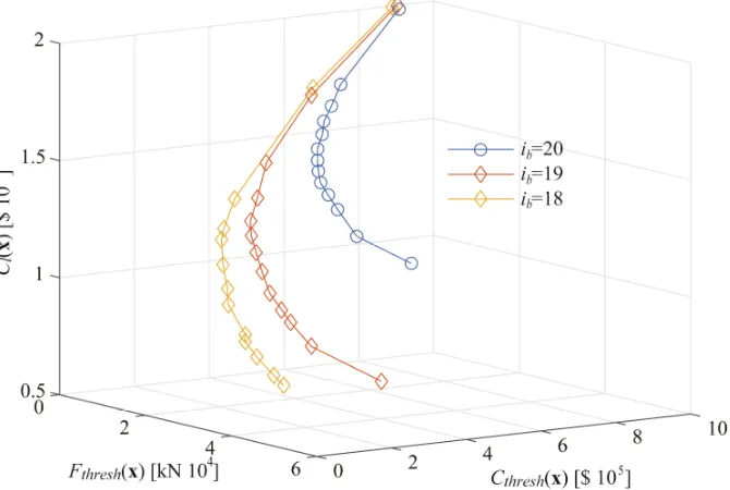
Optimal design results are presented in Figs. 3-5. Figure 3 shows the Pareto front for three objectives [Cl(x)-Cthresh(x)-Fthresh(x)] and three TMDI configurations. Only the continuously varying β case is
presented. Figure 4 presents the projection of this front in the Cthresh(x)-Fthresh(x), the Cl(x)-Fthresh(x) and Cl(x)-Cthresh(x) planes, while optimal values for μ, ζd and fd along the Pareto front [expressed as a
function of Cthresh(x)] are reported in Figure 5. For the continuously varying β case the optimal value is
[image:10.612.99.515.177.621.2]found to be at the boundary of the search domain (β=4.5) and is not reported due to space constraints.
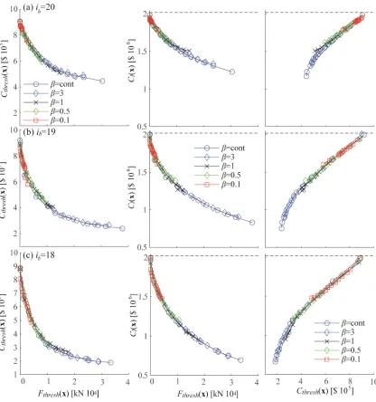
Figure 4. Projection of the Pareto front along pair of objectives (each case presented for different β values). First row corresponds to ib=20, second to ib=19 and third to ib=18.Dashed lines correspond to the performance of the
structure without the TMDI.
The results show that the addition of the TMDI can provide a significant reduction for Cl(x) and Cthresh(x), with the benefits increasing for largerinertance values. This validates the efficiency of the
10
objectives (third column in Figure 4) exhibits an interesting behavior as the two objectives are not competing: simultaneous reduction of both the life-cycle cost and the repair cost is feasible. This is not the case for the TMD (Ruiz et al. 2015), for which reduction of one objective cannot be accomplished without increase of the other along the Pareto front, and clearly demonstrates the mass amplification benefits offered by the TMDI. By adjusting the remaining characteristics of the TMDI, without any increase of its mass, enhanced vibration suppression is feasible. Since the upfront cost is only related to the TMDI mass, this ability enables the reduction of the repair cost without an increase of the upfront cost and therefore reduction also of the life-cycle cost. The optimal TMDI mass (Figure 5) remains close to its minimum considered value across the entire front. The increase in protection efficiency comes, though, with a corresponding increase for the force that needs to be accommodated (larger Fthresh). This objective competes with the other two, demonstrating the value of the
multi-criteria optimization for exploring all candidate solutions that provide different compromises between the TMDI performance objectives. Note also that a plateau is reached for the seismic risk with respect to the Fthresh(x) objective; beyond certain value for Fthresh (different for each βcase) small benefits are
obtained for Cl(x) and Cthresh(x) for significant increase of Fthreshi. This feature, which is common in
[image:11.612.120.495.278.648.2]multi-objective design problems (i.e. large deterioration of one objective for small only benefits for the competing objectives), should be carefully evaluated when making final design decisions.
Figure 5. Optimal values for μ, ζd and fd along the Pareto front [design variables are plotted with respect to the corresponding value of Cthresh(x)]. First row corresponds to ib=20, second to ib=19 and third to ib=18.
11
overlapping in some ranges. The case with β=cont overlaps the other three ones, and has fundamentally different optimal values for the remaining TMDI design variables (Figure 5). This shows that adjustment of the tuning characteristics (ζd and fd) of the TMDI can facilitate similar
performance across some ranges of the examined objectives independent of the inertance value, though larger values for the latter expand these ranges, offering more versatile behaviour. Still it is important to note that performance obtained when β was considered as design variable, and ultimately was optimized to its upper boundary 4.5, is similar in some parts of the Pareto front to the performance obtained for much smaller value of β=1. This demonstrates the importance of carefully examining the impact of the inertance on the established performance, considering of course all practical constraints with respect to the available inerter devices.
With respect to the topological configuration, connection of inerter to a lower floor provides significantly better behavior across all examined objectives (Figure 4) and with fundamentally different optimal design configurations (Figure 5). Cl(x) and Cthresh(x) are reduced for id=19 (compared
to id=20) or id=18 (compared to id=19), something that agrees with the trend reported in (Giaralis and
Taflanidis 2017) considering a simplified stationary response. Additionally the results here show that the Fthresh is also reduced for the smaller id values, meaning that enhanced protection is offered with a
smaller demand with respect to the forces that need to be accommodated. This stresses the importance of connecting the inerter to the lowest floor possible, subject of course to architectural constraints.
6. CONCLUSSIONS
The multi-objective design of supplemental seismic protective devices considering life-cycle performance criteria was discussed in this paper, focusing on application to TMDIs for seismic protection of multi-story buildings in the region of Chile. Life-cycle performance was evaluated using time-history analysis for describing structural behavior, an assembly-based vulnerability approach for quantifying earthquake losses, and characterization of the earthquake hazard through stochastic ground motion modeling. Three different criteria were utilized in the design optimization. The first one, representing the direct benefits from the damper implementation, is the life-cycle cost of the system, composed by the device upfront cost and the anticipated seismic losses over the lifetime of the structure. For the TMDI application the upfront device cost was related only to the TMDI mass. The additional criteria correspond to performance quantities with specific probability of exceedance over the life-cycle of the structure. For the TMDI application two such criteria were adopted, the repair cost, incorporating in the design risk-aversion attitudes in the design, and the inerter force, considering practical constraints for the force transmitted from the TMDI to the structure. A multi-objective optimization was established considering these three objectives while stochastic simulation techniques were used to obtain all risk measures. A Kriging metamodeling approach was adopted for facilitating an efficient design optimization. A case study was presented employing a specific 21-story building located in Santiago, Chile. Three different topological configurations were examined with TMDI mass attached at the top floor and inerter connecting that mass to the floor either one, two or three stories below. The results show that the proposed design framework facilitate a clear demonstration of the benefits of the TMDI over the TMD. The mass-amplification effect facilitated by the TMDI inertance allowed the TMDI to accomplish a simultaneous reduction of both the life-cycle cost and the repair cost along the Pareto front. This comes, though, at the expense of increased inerter forces that need to be transferred by the TMDI to the supporting structure. Results also showed that lower inertance values reduce the extent of the Pareto front, and therefore of the dominant designs available for the stakeholder to make the final decision, stressing the importance of technological advances that can produce devices that can accommodate higher inertance values. Connecting the inerter to lower floor also provides considerable benefits across all examined performance criteria and so should be preferred if such a configuration is feasible considering architectural constraints.
7. ACKNOWLEDGMENTS
12 8. REFERENCES
EERI Special Earthquake Report. (2010). "Learning from Earthquakes: The Mw 8.8 Chile Earthquake of February 27, 2010." Earthquake Engineering Research Institute.
Giaralis, A., and Marian, L. (2016)."Use of inerter devices for weight reduction of tuned mass-dampers for seismic protection of multi-story building: the Tuned Mass-Damper-Interter (TMDI)." SPIE 9799, Active and Passive Smart Structures and Integrated Systems 20-24 March, Las Vegas, Nevada, doi:10.1117/12.2219324. Giaralis, A., and Petrini, F. (2017). "Wind-induced vibration mitigation in tall buildings using the tuned mass-damper-inerter." Journal of Structural Engineering, 143(9), 04017127.
Giaralis, A., and Taflanidis, A. (2017). "Optimal tuned mass‐damper‐inerter (TMDI) design for seismically excited MDOF structures with model uncertainties based on reliability criteria." Structural Control and Health Monitoring, DOI: 10.1002/stc.2082.
Gidaris, I., and Taflanidis, A. A. (2015). "Performance assessment and optimization of fluid viscous dampers through life-cycle cost criteria and comparison to alternative design approaches." Bulletin of Earthquake Engineering, 13(4), 1003-1028.
Gidaris, I., Taflanidis, A. A., and Mavroeidis, G. P. (2017). "Multiobjective design of supplemental seismic protective devices utilizing lifecycle performance criteria." Journal of Structural Engineerinf, ASCE, in press. Goulet, C. A., Haselton, C. B., Mitrani-Reiser, J., Beck, J. L., Deierlein, G., Porter, K. A., and Stewart, J. P. (2007). "Evaluation of the seismic performance of code-conforming reinforced-concrete frame building-From seismic hazard to collapse safety and economic losses." Earthquake Engineering and Structural Dynamics, 36(13), 1973-1997.
Leyton, F., Ruiz, S., and Sepulveda, S. A. (2009). "Preliminary re-evaluation of probabilistic seismic hazard assessment in Chile: from Arica to Taitao Peninsula." Advances in Geosciences, 22(22), 147-153.
Marian, L., and Giaralis, A. (2013)."Optimal design of inerter devices combined with TMDs for vibration control of buildings exposed to stochastic seismic excitations." 11th International Conference on Structural Safety and Reliability, June 16-20, New York, US, 1025-1032.
Marian, L., and Giaralis, A. (2014). "Optimal design of a novel tuned mass-damper-inerter (TMDI) passive vibration control configuration for stochastically support-excited structural systems." Probabilistic Engineering Mechanics, 38, 156-164.
Ruiz, R., Taflanidis, A. A., Lopez-Garcia, and Vetter, C. (2015). "Life-cycle based design of mass dampers for the Chilean region and its application for the evaluation of the effectiveness of tuned liquid dampers with floating roof." Bulletin of Earthquake Engineering, 14(3), 943-970.
Ruiz, R., Giaralis, A., Taflanidis, A., and Lopez-Garcia, D. (2017)."Risk-informed optimization of the tuned mass-damper-inerter (TMDI) for seismic protection of buildings in Chile." 16th World Conference on Earthquake Engineering, January 9-13. , Santiago, Chile.
Shin, H., and Singh, M. P. (2014). "Minimum failure cost-based energy dissipation system designs for buildings in three seismic regions Part II: Application to viscous dampers." Engineering Structures, 74, 275-282.
Smith, M. C. (2002). "Synthesis of mechanical networks: the inerter." Automatic Control, IEEE Transactions on, 47(10), 1648-1662.
Spall, J. C. (2003). Introduction to stochastic search and optimization, Wiley-Interscience, New York.
Taflanidis, A. A., and Beck, J. L. (2009). "Life-cycle cost optimal design of passive dissipative devices."
Structural Safety, 31(6), 508-522.
Tse, K. T., Kwok, K. C. S., and Tamura, Y. (2012). "Performance and cost evaluation of a smart tuned mass damper for suppressing wind-induced lateral-torsional motion of tall structures." Journal of Structural Engineering, 138(4), 514-525.
Vetter, C., Taflanidis, A. A., and Mavroeidis, G. P. (2016). "Tuning of stochastic ground motion models for compatibility with ground motion prediction equations." Earthquake Engineering & Structural Dynamics, 45(6), 893-912.

![Figure 5. Optimal values for μ, ζd and fd along the Pareto front [design variables are plotted with respect to the corresponding value of Cthresh(x)]](https://thumb-us.123doks.com/thumbv2/123dok_us/1389208.92064/11.612.120.495.278.648/figure-optimal-pareto-variables-plotted-respect-corresponding-cthresh.webp)