Int. J. Electrochem. Sci., 11 (2016) 7099 – 7110, doi: 10.20964/2016.08.60
International Journal of
ELECTROCHEMICAL
SCIENCE
www.electrochemsci.org
Effects of Complexing Agents and Current Density on Carbon
Content of Trivalent Chromium Carbon Coating and Its
Properties
Hung-Hua Sheu1,*, Chien-Hung Lin2, Shun-Yi Jian1, Hung-Bin Lee3,*, Bing-Ruei Yang1, Ming-Der Ger1
1
Department of Chemical and Materials Engineering, Chung Cheng Institute of Technology, National Defense University, Taoyuan City, Taiwan
2
Department of Physics, ROC Military Academy, Feng-Shan, Kaohsiung, Taiwan
3
Department of Materials Science and Engineering, Da-yeh University, Dacun, Changhua,Taiwan
*
E-mail: [email protected], [email protected], [email protected]
Received: 29 April 2016 / Accepted: 11 June 2016 / Published: 7 July 2016
Chromium carbon coatings were electroplated from trivalent chromium chloride based electrolyte at different complex agents such as HCOONH4, HCOONa and Glycine. The effects of different complex
agents on morphology, chemical composition, contact angle, ICR values and corrosion resistance of coatings were investigated. All the electroplated conditions indicated that the carbon content within chromium carbon coatings decreased with an increase of current density due to the chelation strength of complexing agents in the bath collapsed by a higher drive force (higher current density). Results also presented that the chromium carbon coatings electroplated from “HCOONa” will form granular structure with an increase of current density, and leading to a poor ICR values. Both coatings electrodeposited from “HCOONH4” and “Glycine” has better contact angle (about 105 and 112º) and
ICR values (<20 mΩcm2 at 160 N cm-2), but the “Glycine” has a poor corrosion resistance. In this study, chromium carbon coatings electroplated from“HCOONH4” have better contact angle (105º),
ICR values (<20 mΩcm2
at 160 N cm-2) and corrosion resistance (3.90×10⁻⁷ A/cm2), and has high application potential in bipolar plates.
Keywords: chromium carbon coatings; complexing agents; contact angle; ICR values
1. INTRODUCTION
chromium compounds are not toxic and its electrolyte is less toxicity than that of hexavalent chromium bath [2-10]. Therefore, trivalent chromium electrodeposition should be a practical replacement for highly toxic hexavalent chromium electrodeposition.
In recently years, several researchers [11-15] have developed the chromium-carbon alloy coatings using trivalent chromium bath. The main carbon ions source of trivalent chromium-carbon alloy coatings comes from a complex agent such as formic acid, ammonium formate, acetic acid, oxalic acid, etc. [16-18]. The literatures have pointed out that the trivalent chromium-carbon alloy deposit possessed a very high hardness (about 1600 Hv) after annealing at 600℃, due to the fine Cr23C6 and Cr7C3 compounds precipitated in the chromium-carbon alloy deposit [19]. Therefore, the
chromium-carbon alloy coatings after annealing will increase its wear and corrosion resistance and have a potential in industrial applications. Bipolar plate, the most important component in polymer electrolyte membrane fuel cells (PEMFC) system, the requirement of an excellent bipolar plate materials included high corrosion resistance, low interfacial contact resistance, low cost, high mechanical strength and high gas impermeability [20]. Past studies have shown that the chromium-carbon alloy coatings can improve the efficacy of PEMFC in simulated conditions due to the excellent characteristics of chromium-carbon alloy coatings such as high electrical and thermal conductivity, corrosion resistance, mechanical strength and wear resistance [21-24].
In the present work, attempts were made to investigate the effects of carbon content within coatings obtained from different complex agents in bath and current density on the corrosion resistance, contact angle and interfacial contact resistance of trivalent chromium carbon coatings. The suitable complex agents in the bath to electroplate Cr-C coatings can be choose and applied in functional coatings such as BPs, anti-sticking coating and self-cleaning coatings.
2. EXPERIMENTAL
[image:2.596.48.548.635.766.2]Commercial brass (30 at.% Zn, 0.05 at.% Fe, 0.05 at.% Pb, remainder Cu), shaped in a square of 50X50 mm and a thickness of 2 mm, was used as the substrate for trivalent chromium carbon electroplating. The surface of brass substrate was grinded with #2000 silicon sandpaper, degreased with acetone for 2 min, activated by 3% NaOH solution for 1 min, pickled in a hydrochloric acid solution (HCl (35%): water = 1:1) for 5 min and then prepared for trivalent chromium carbon electroplating.
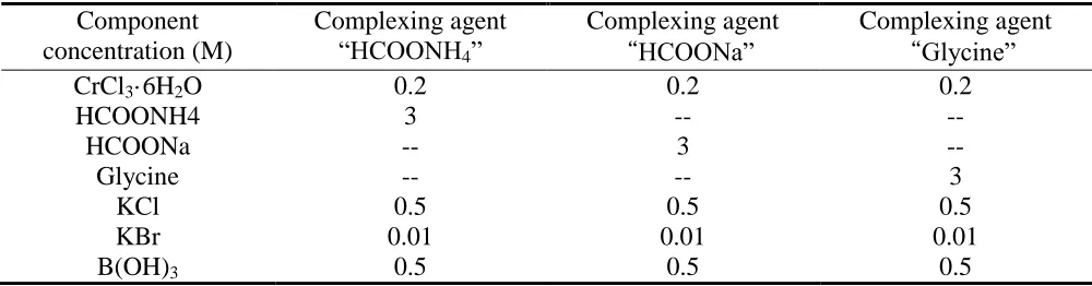
Table 1. The composition of electrolyte baths for trivalent chromium carbon electroplating Component
concentration (M)
Complexing agent “HCOONH4”
Complexing agent “HCOONa”
Complexing agent “Glycine”
CrCl3·6H2O 0.2 0.2 0.2
HCOONH4 3 -- --
HCOONa -- 3 --
Glycine -- -- 3
KCl 0.5 0.5 0.5
KBr 0.01 0.01 0.01
The trivalent chromium carbon deposits were electroplated in a plating bath containing 0.2 M CrCl3·6H2O as the main metal salt, different complexing agents included 3 M ammonium formate, 3
M sodium formate and 3 M glycine were used in electroplating process, 0.01 M KBr and 0.5 M KCl were also added into the electrolyte. 0.5 M B(OH)3 was used as buffer salt in the plating bath. The
composition of electrolyte baths for trivalent chromium carbon electroplating was listed in Table 1. The pH value of electrolyte was maintained at 4.5 and all electroplating temperatures were carried out at 10±1℃. All of trivalent chromium carbon deposits were rinsed in distilled water and dried in air at room temperature for 24 h.
Using an Autolab-PGSTAT30 potentiostat/galvanostat controlled by a GPES (General Purpose Electrochemical system) software to carry out the potentiodynamic polarization tests, a platinum sheet and a Ag/AgCl electrode in a saturated solution of 3.5% NaCl were used as the counter and reference electrodes at room temperature, respectively. The linear polarization curves were measured in the potential range from -0.3 V to 0.5 V with a scanning rate at 0.5 mV/s. Before the tests, the specimens were degreased and rinsed with deionized water.
Scanning electro-microscopy (SEM) was used to analyze the microstructure and morphology of trivalent chromium carbon deposits. The distribution of Cr, C and O in the coatings was measured by an electron probe X-ray micro-analyzer (EPMA). The crystalline structures and constituent phases of deposits were measured by X-ray diffraction (XRD) with a Cu kα radiation (λ=0.15405 nm) over a scanning range from 10º to 80º.
Previous studies are well documented the analysis technique of interfacial contact resistance [25]. In this study, the interfacial contact resistance between the specimens and gas diffusion layer (GDL) was evaluated by a method similar to that reported by Bai et al. [26]. For measuring the contact resistance, two pieces of carbon paper were sandwiched between the specimen and two copper plates. During the tests, a constant electrical current of 1 A was flowed through the copper plates, and the voltage drop was recorded by a digital multi-meter (M3500A, Picotest, USA). The variation in the total voltage with respect to the compaction force that was steadily increased from 0 to 200 N/cm2 was recorded every 10 N/cm2.
Contact angle of trivalent chromium carbon deposit with water was measured by a contact angle goniometer (FACE CA-5 150, Tantec, USA) under room temperature to investigate the surface energy. All measurements of contact angle were repeated five times on other places of the same specimen. The reported value for each sample is the mean of five measurements.
3. RESULTS AND DISCUSSION
3.1. Effects of different complexing agents in corrosion resistance, contact angle and interfacial contact resistance in trivalent chromium carbon coatings
Fig. 1 shows SEM morphologies of trivalent chromium carbon coatings plated at fixed current density (10 A/dm2) for 10 min in the trivalent chromium bath with different complex agents (i.e. HCOONH4, HCOONa and Glycine). It can observe that all the deposits plated under different complex
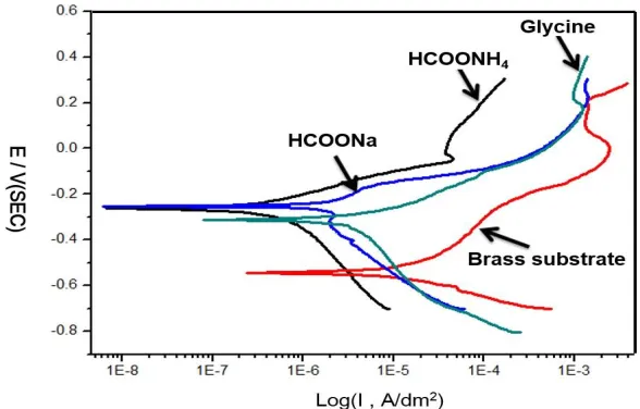
Fig. 2 shows potentiodynamic polarization curves for brass substrate and Cr-C coatings deposited from the trivalent chromium bath with different complexing agents and electroplated for 10 min. The experimental results are also summarized in Table 1. In general, the brass substrates have poor corrosion resistance against chlorine ions and it must be protected by some coatings. In our previous studies, indicated the trivalent Cr-C coatings have excellent corrosion resistance and can protect the substrates from the corrosion condition such as in 3.5% NaCl solution [27].
Figure 1. SEM morphologies of trivalent chromium carbon deposits formed from different complex agents (a) HCOONH4, (b) HCOONa, (c) Glycine (plating time is fixed at 10 min).
[image:4.596.63.533.189.319.2]Figure 2. Polarization curves of brass substrate and Cr-C coatings electroplated by different complex agents measured in a 3.5% NaCl solution at 25℃.
Table 2. Ecorr and icorr for brass and Cr-C coatings electroplated by different complex agents measured
in a 3.5% NaCl solution at 25℃
complexing agents βa (V/ decade) βc (V/ decade) i corr (A/cm2) E corr (V vs. SCE)
Substrate (Brass) 0.208 -0.159 1.16×10⁻⁵ -0.57
HCOONH4 0.084 -0.075 3.90×10⁻⁷ -0.26
HCOONa 0.091 -0.126 2.56×10⁻⁶ -0.27
[image:4.596.148.442.377.565.2] [image:4.596.57.543.665.741.2]
Table 2 shows the corresponding corrosion parameters, including corrosion potential, corrosion current density, anodic Tafel slope βa and cathodic Tafel slope βc for brass and Cr-C coatings electroplated by different complex agents measured in a 3.5% NaCl solution at 25℃, it presents the substrates deposited Cr-C coatings have better corrosion resistance than that without Cr-C coatings. Without Cr-C coatings, the icorr of brass substrate is approximately 1.16×10⁻⁵ A/cm2, the icorr of
specimens deposited Cr-C coatings from the bath with different complexing agents are about 3.90×10⁻⁷ (HCOONH4), 2.56×10⁻⁶ (HCOON a) and 5.46×10⁻⁶ A/cm2 (Glycine), respectively. The experimental
results reveal the Cr-C coating deposited from the bath with HCOONH4 has the best corrosion
resistance. This should be the Cr-C coating deposited from the bath with HCOONH4 is uniform
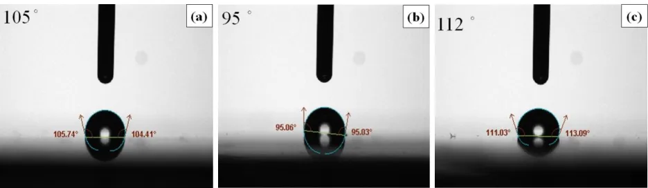
covering on the brass substrate and protect the substrate from the corrosion condition (Fig. 1). Fig. 3 presents the contact angle of the Cr-C coatings electroplated with different complexing agents and the chemical compositions of coatings are also listed in Table 3.
Figure 3. Contact angle of the Cr-C coatings electroplated from the bath with different complexing agents (a) HCOONH4, (b) HCOONa, and (c) Glycine.
Table 3. The chemical composition of chromium-carbon coatings electroplated at various conditions for 10 min (current density at 10 A/dm2)
Operated conditions Chemical composition
Cr (at. %) C (at. %) O (at. %)
HCOONH4-10 A/dm2-10min 56.49 41.66 1.85
HCOONa-10 A/dm2-10min 73.26 24.56 2.14
Glycine-10 A/dm2-10min 44.90 51.72 3.28
The results reveal that the contact angle increased with an increase of carbon content within the coatings. The maximum contact angle 112º is obtained from the Cr-C coating electroplated with Glycine due to its higher carbon content (about 51.72 at. %) and smooth surface. The contact angle of Cr-C coating electroplated with “HCOONH4” is only about 105º and smaller than that of “Glycine”
[image:5.596.65.533.289.425.2] [image:5.596.84.519.538.609.2]
“HCOONH4” and “Glycine” have excellent hydrophobic and would be applied suitably in bipolar
plates and anti- sticking coatings. Unfortunately, the coating electroplated from “Glycine” has poor corrosion resistance than that of“HCOONH4”. Therefore, the coating electroplated from“HCOONH4”
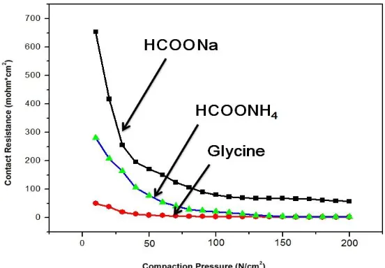
would has the best application in bipolar plates, anti-sticking coating and self-cleaning coatings. Fig. 4 shows the relationship of Cr-C coatings electroplated from the bath with different complexing agents between contact resistances and compaction pressure (the analysis technique of interfacial contact resistance was described in experimental section). All specimens reveal that the interfacial contact resistances (ICR) reduce significantly with an increase of compaction force. The results presents Cr-C coating electroplated from the bath with “Glycine” has the lowest ICR (about 15 mΩcm2
) when the compaction force increases from 50 to 200 Ncm-2, “HCOONa” has the highest ICR about 90 mΩcm2
when the compaction force increases from 100 to 200 Ncm-2.
Figure 4. Interfacial contact resistance between the Cr-C coatings deposited with different complex agents and gas diffusion layer at various compaction pressures.
Moreover, the ICR of Cr-C coating electroplated from the bath with “HCOONH4” reduces to
15 mΩcm2
when the compaction forces greater than 150 Ncm-2. By comparing with Fig. 4 and Table 3, the ICR of Cr-C coatings electroplated from the bath with different complexing agents will decrease with an increase of carbon content within Cr-C coatings.
Therefore, both ICR values of Cr-C coatings electroplated from the bath with “HCOONH4”
and “Glycine” can reach the U.S. DOE standard applied at BPs (<20 mΩcm2 at 160 N cm-2) [29].
3.2. Effects of different current density, contact angle and interfacial contact resistance in trivalent chromium carbon coatings
[image:6.596.160.436.283.475.2]
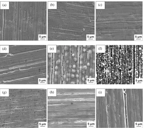
A/dm2), the cracks present in higher operated current density due to the residual stress in the Cr-C coating and the creation of hydrogen bubbles during electroplating [30]. Fig. 5(d)-(f) reveal the Cr-C coatings formed from the bath with “HCOONa”, the coarsen granular structure formed within Cr-C coating at current density 20 A/dm2, a smaller homogeneous granular structure formed within Cr-C coating at current density 30 A/dm2, the formation of granular can be attributed to a fewer nucleation sites than that of“HCOONH4” at the same current density conditions. Fig. 5(g)-(i) show the surface
[image:7.596.62.539.253.678.2]morphologies of Cr-C coatings electroplated from the bath with “Glycine”, it can be observed the marks of brass substrates still remain on surface after electroplating at different current density, and indicated the Cr-C coatings deposited from “Glycine” are very thin due to the lowest electrodeposited rate.
Figure 5. SEM surface morphologies of Cr-C coatings electroplated under different complexing agents and current density for 10 min: (a)“HCOONH4”-10 A/dm2, (b) “HCOONH4”-20 A/dm2, (c)
“HCOONH4”-30 A/dm2, (d) “HCOONa”-10 A/dm2, (e) “HCOONa”-20 A/dm2, (f)
“HCOONa”-30 A/dm2, (g) “Glycine”-10 A/dm2, (h) “Glycine”-10 A/dm2, (i) “Glycine”-10
A/dm2.
(a) (b) (c)
(d) (e) (f)
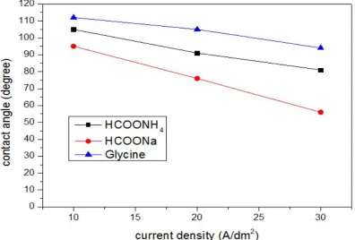
Figure 6. The contact angles of Cr-C coatings electroplated at different complexing agents and current density.
Fig. 6 presents the contact angles of Cr-C coatings electroplated at different complexing agents and current density, the results show the contact angles decrease with an increase of current density in all kinds of complexing agent baths due to the lower carbon content within Cr-C coatings (Table 4).
Table 4 show the chemical compositions of Cr-C coatings electroplated from various operated condition, the carbon content significantly reduce with an increase of current density, and it can be attributed to the chelation strength of complexing agents in the bath collapsed by a higher drive force (higher current density). In “HCOONa” condition, the carbon content are significantly lower than that of “HCOONH4” and “Glycine”, the carbon content is only about 10.36 and 6.61 at. % when current
density operated at 10 and 20 A/dm2, respectively. On the other hand, the coatings electroplated from “HCOONa” may be belong Cr coatings not Cr-C coatings and the typical granular structure will form within the coatings. The rough surface of coatings electroplated from “HCOONa” at 10 and 20 A/dm2 will reduce the contact angle significantly; therefore, in this study, the Cr-C coatings deposited from“HCOONH4” have the highest contact angle, the “HCOONa” has the worst contact angles.
Moreover, the carbon content of Cr-C coatings electroplated from “Glycine” have higher carbon content between 42.44 to 51.72 at.%, due to the complexing agent “Glycine” has the best chelation strength in the trivalent chromium bath.
Table 4. The chemical composition of chromium-carbon coatings electroplated at various conditions
Operated conditions Chemical composition
Cr (at. %) C (at. %) O (at. %)
HCOONH4-10 A/dm2-10min 56.49 41.66 1.85
HCOONH4-20 A/dm2-10min 75.19 23.89 1.37
HCOONH4-30 A/dm2-10min 79.63 18.55 2.76
HCOONa-10 A/dm2-10min 73.26 24.56 2.14
HCOONa-20 A/dm2-10min 87.65 10.36 1.98
HCOONa-30 A/dm2-10min 91.64 6.61 1.73
Glycine-10 A/dm2-10min 44.90 51.72 3.28
Glycine-20 A/dm2-10min 52.22 45.63 2.13
[image:9.596.129.462.511.752.2]Glycine-30 A/dm2-10min 52.63 42.44 4.91
Table 5. The icorr and Ecorr of chromium-carbon coatings electroplated at various conditions
Operated conditions βa (V/ decade) βc (V/ decade) i corr (A/cm2) E corr (V)
Substrate (Brass) 0.208 -0.159 1.16×10⁻⁵ -0.57
HCOONH4 -10 A/dm2-10min 0.059 -0.042 3.90×10⁻⁷ -0.26
HCOONH4 -20 A/dm2-10min 0.043 -0.038 4.10×10⁻⁷ -0.34
HCOONH4 -30 A/dm2-10min 0.154 -0.158 1.06×10⁻⁶ -0.41
HCOONa -10 A/dm2-10min 0.133 -0.195 2.56×10⁻⁶ -0.27
HCOONa -20 A/dm2-10min 0.042 -0.047 3.79×10⁻⁷ -0.27
HCOONa -30 A/dm2-10min 0.088 -0.047 4.08×10⁻⁷ -0.27
Glycine -10 A/dm2-10min 0.032 -0.080 5.46×10⁻⁶ -0.31
Glycine -20 A/dm2-10min 0.050 -0.053 4.38×10⁻⁶ -0.29
[image:10.596.113.480.81.626.2]
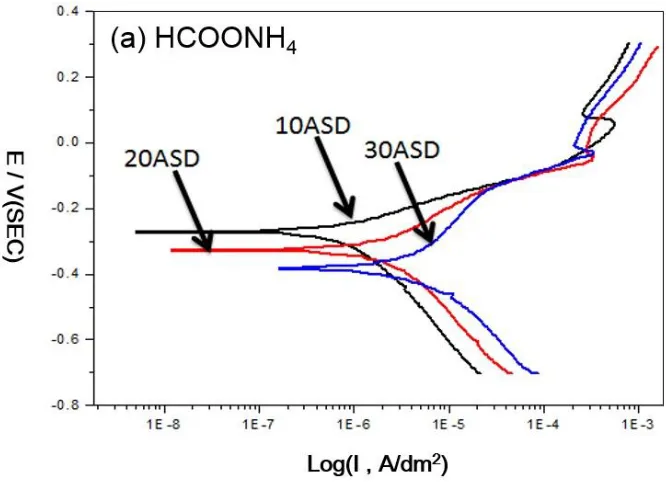
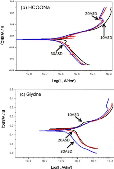
Figure 7. Polarization curves measured in 3.5 % NaCl solution for the Cr-C coatings electroplated at different complexing agents and current density (a) HCOONH4, (b) HCOONa and (c) Glycine.
Fig. 7(a) presents the polarization curves of Cr-C coatings electroplated from “HCOONH4” at
different current density (10, 20 and 30 A/dm2), the icorr is about 3.90×10⁻⁷, 4.10×10⁻⁷ and 1.06×10⁻⁶
of icorr and Ecorr are also listed in Table 4. The results reveal that the coatings electroplated
from“HCOONH4” at 10 and 20 A/dm2 has better corrosion resistance, the coatings electroplated from
“HCOONa” at 20 and 30 A/dm2
has better corrosion resistance, all the coatings electroplated from “Glycine” have the worst corrosion resistance. Here, the Cr-C coatings electroplated from “HCOONa” may be has better corrosion resistance, but their contact angles have a poor performance due to the formation of granular structure (Fig. 3(b) and Fig. 5(f)). Therefore, the Cr-C coatings electroplated from “HCOONa” cannot be applied at BPs. On the other hand, the Cr-C coatings electroplated from “HCOONH4” are suitable for application at BPs due to their better contact angle, ICR values and
corrosion resistance.
4. CONCLUSIONS
Trivalent chromium carbon coatings were electroplated from trivalent chromium chloride based electrolyte at different complex agents and current density. The results showed that:
1. All the contact angles of Cr-C coatings decreased with an increase of current density due to a decrease of carbon content within Cr-C coatings. The highest contact angle of Cr-C coatings is electrodeposited from “Glycine” (about 112º), and the lowest contact angle is electrodeposited from “HCOONa”, due to the different chelation strength in various complex agents such as “HCOONH4”,
“HCOONa” and “Glycine”.
2. Both ICR values of Cr-C coatings electroplated from the bath with “HCOONH4” and
“Glycine” can reach the U.S. DOE standard applied at BPs (<20 mΩcm2
at 160 N cm-2).
3. The Cr-C coatings electroplated from“HCOONH4” have better contact angle, ICR
values and corrosion resistance than that of “HCOONa” and “Glycine”. Therefore, it is suitable for application at some field such as BPs, anti-sticking coating and self-cleaning coatings.
ACKNOWLEDGEMENTS
The authors would like to thank the Ministry of Science and Technology of the Republic of China, Taiwan, for financially supporting this research under Contract No. MOST 105-2622-E-606-001-CC2.
References
1. L. Gianelos, Plating and Surface Finishing, 66 (1979) 56. 2. Y. B. Song, D.T. Chin, Acta Electrochimica, 48 (2002) 349.
3. S. Surviliene, V. Jasulaitiene, O. Nivinskiene, A. Cesuniene, Appl. Surf. Sci., 253 (2007) 6738. 4. S. Ghaziof, M.A. Golozar, K. Raeissi, J. Alloy. Comp., 496 (2010) 164.
5. R. Giovanardi, G. Orlando, Surf. Coat. Technol., 205 (2011) 3947. 6. G. Saravanan, S. Mohan, Corros. Sci., 51 (2009) 197.
7. O.V. Safonova, L.N. Vykhodtseva, N.A. Polyakov, J.C. Swarbrick, M. Sikora, P. Glatzel, V.A. Safonov, Acta Electrochimica, 56 (2010) 164.
8. V.S. Protsenko, F.I. Danilov, V.O. Gordiienko, S.C. Kwon, M. Kim, J.Y. Lee, Thin Solid Films, 520 (2011) 380.
10.M.A.S. Rodrigues, R.F. Dalla Costa, A.M. Bernardes, J. Zoppas Ferreira, Acta Electrochimica, 47 (2001) 753.
11.C.E. Lu, J.L. Lee, H.H. Sheu, K.H. Hou, C.C. Tseng, M.D. Ger, International Journal of Electrochemical Science, 10 (2015) 5404.
12.Z. Zeng, L. Wang, A. Liang, J. Zhang, Acta Electrochimica, 52 (2006) 1366.
13.V.S. Protsenko, V.O. Gordiienko, F.I. Danilov, Electrochemistry Communications, 17 (2012) 85. 14.S. Ghaziof, K. Raeissi, M.A. Golozar, Surf. Coat. Technol., 205 (2010) 2174.
15.C.A. Huang, Y.W. Liu, C. Yu, C.C. Yang, Surf. Coat. Technol., 205 (2011) 3461. 16.V.S. Protsenko, F.I. Danilov, Acta Electrochimica, 54 (2009) 5666.
17.Z. Zeng, Y. Sun, J. Zhang, Electrochemistry Communications, 11 (2009) 331.
18.C.E. Lu, N.W. Pu, K.H. Hou, C.C. Tseng, M.D. Ger, Applied Surface Science, 282 (2013) 544. 19.S.C. Kwon, M. Kim, S.U. Park, D.Y. Kim, D. Kim, K.S. Nam, Y. Choi, Surf. Coat. Technol., 183
(2004) 151.
20.A. Hermann, T. Chaudhuri, P. Spagnol, International Journal of Hydrogen Energy, 30 (2005) 1297.
21.Y. Fu, G. Lin, M. Hou, B. Wu, Z. Shao, B. Yi, International Journal of Hydrogen Energy, 34 (2009) 405.
22.C.Y. Bai, T.M. Wen, K.H. Hou, M.D. Ger, Journal of Power Sources, 195 (2010) 779.
23.C.Y. Bai, T.M. Wen, M.S. Huang, K.H. Hou, M.D. Ger, S.J. Lee, Journal of Power Sources, 195 (2010) 5686.
24.T.M. Wen, K.H. Hou, C.Y. Bai, M.D. Ger, P.H. Chien, S.J. Lee, Corrosion Science, 52 (2010) 3599.
25.M.S. Park, Y.M. Kang, J.H. Kim, G.X. Wang, S.X. Dou, H.K. Liu, Carbon, 46 (2008) 35. 26.C.Y. Bai, T.M. Wen, K.H. Hou, M.D. Ger, Journal of Power Sources, 195 (2010) 779.
27.H.H. Sheu, C.E. Lu, K.H. Hou, M.L. Kuo, M.D. Ger, Journal of the Taiwan Institute of Chemical Engineers, 48 (2015) 73.
28.H.C. Wang, K.H. Hou, C.E. Lu, M.D. Ger, Thin Solid Films, 570 (2014) 209.
29.United States Department of Energy, Energy Efficiency and Renewable Energy, Fuel Cell Technologies Program. 2007. Technicalplan-fuelcells.website: http://www1.eere.energy. gov/hydrogenandfuelcells/mypp/pdfs/fuel_cells.pdf ; 2011.
30.M.E. Bahrololoom, A. Hoveidaei, Surface Engineering, 15 (1999) 502.