Magnet Eddy Current Loss Reduction in Permanent Magnet Machines
Full text
Figure


Related documents
6 The t- and θ- component of the the magnetic flux density waveform in the pitch circle of the air-gap (i.e., Subdomain VI) at a) no-load, and b) on-load condition in M3 machine. 7
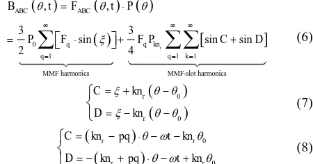
The analytic approach adopted in this work consider that the magnetic flux density in the air gap of PMSM machine is the product of magnetic flux density generated by rotor magnet
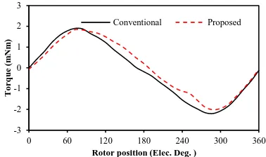
The influence of pole-slot match on cogging torque is analyzed, and the effects of number of stator slots and the number of slots per rotor pole on cogging torque are
cogging torque developed by permanent magnet machines is inves- tigated. It is shown that the slot and pole number combination has a significant effect on the cogging torque,
accurately in PM machines which employ axial segmentations as a means of reducing eddy current loss, 3D FEAs are usually applied [11]-[16]. However, 3D FEAs are usually
This paper investigates the influence of eddy current losses in multi-stranded bundle conductors employed in out- runner permanent magnet machines, by adopting
This paper investigates the influence of eddy current losses in multi-stranded bundle conductors employed in out- runner permanent magnet machines, by adopting
Figure 3 shows closed loop current control of a PMSM using FOC method. Torque and flux current are decoupled to generate the free torque and flux control. Both torque and flux are
