“I hereby declare that I have read through this report entitle “Electrostatic Chamber Development for Dust Collector” and found that it has been comply the partial fulfillment for awarding the degree of Bachelor of Electrical Engineering (Industrial Power)”.
Signature : ……….
Supervisor’s Name : DR. FARHAN BIN HANAFFI
ELECTROSTATIC CHAMBER DEVELOPMENT FOR DUST
COLLECTOR
IZZAIM DANISH FATHULLAH BIN AHMAD AZHAR
This report is submitted in partial fulfillment of the requirements for the degree of the Bachelor of Electrical of Electrical Engineering (Industrial Power)
Faculty of Electrical Engineering
UNIVERSITI TEKNIKAL MALAYSIA MELAKA
“I declare this report entitle “Electrostatic Chamber Development for Dust Collector” is the result of my own research except as cited in the references. The report has not been accepted for any degree and is not concurrently submitted in candidature of any other degree”.
Signature : ……….
Name : IZZAIM DANISH FATHULLAH BIN AHMAD AZHAR
i
ACKNOWLEDGEMENT
Alhamdulillah, praise be to Allah, the most gracious and merciful, the lord of universe and may blessing and peace of Allah be upon his messenger Muhammad S.A.W, for giving me wellness and ideas to complete this final project report. Without any of it, I surely cannot complete this project in the time given.
First of all, very special thanks to my parents for the continuous support throughout my day and for their time, concern, efforts and always encouraging me to complete this project. A million thanks to my supervisor, Dr. Farhan bin Hanaffi because always provide tutoring, guidance and always give beneficial knowledge, good advice and always giving the collaboration in order to move forward. Furthermore, I would like to thanks to Assistant Engineer Mr. Wahyudi for guide and giving his opinion on my project.
Finally, thanks to all that involved directly or indirectly in the completion of this final report of Final Year Project (FYP). All the kindness that are given by them will not forgotten.
ii
ABSTRACT
iii
ABSTRAK
Penangkap habuk elektrostatik adalah sejenis bekas yang berfungsi untuk memerangkap habuk atau zarah. Fungsinya adalah berdasarkan Electrostatic Precipitator(ESP) yang mana digunakan secara meluas dalam industry sebagai alat yang
iv
TABLE OF CONTENTS
CHAPTER TITLE PAGE
ACKNOWLEDGEMENT
ABSTRACT
ABSTRAK
TABLE OF CONTENTS
LIST OF TABLES
LIST OF FIGURES
i ii iii iv vi vii
1 INTRODUCTION
1.1 Motivation
1.2 Project Background 1.3 Problem Statement 1.4 Objectives
1.5 Scope
1 1 1 3 3 4
2 LITERATURE REVIEW
2.1 Introduction 2.2 Ionization Process
2.2.1 Ionization by Collision 2.2.2 Photo-ionization
2.2.3 Secondary Ionization Process 2.2.4 Electron Attachment Process 2.3 Corona Discharge
2.4 Operational Properties of ESP 2.5 Gap between Plate of ESP 2.6 Design of Electrode
2.7 Dielectric and Electrical Properties
5 5 6 6 7 8 9 10 11 13 14 15
3 METHODOLOGY
3.1 Project Implementation 3.2 Design of Chamber
17
v
3.3 Development of Chamber 3.3.1 Wire
3.3.2 Aluminium Plate 3.3.3 Type of Dust 3.3.5 Acrylic Box
3.3.6 Trek Model P0621N 3.3.7 DC Power Supply 3.4 Collecting Data
19 19 19 20 20 21 22 23
4 RESULT AND DISCUSSION
4.1 Size of Cable
4.2 Size and Type of Particle 4.3 Supply Voltage
25
25 26 28
5 CONCLUSION AND RECOMMENDATION
5.1 Conclusion 5.2 Recommendation
vi
LIST OF TABLES
Table Title Page
Table 2.1 Guideline by WHO 5
Table 2.2 Comparison of Plate Spacing 13
Table 3.1 Specification of Trek Model P0621N 21
vii
[image:10.595.75.499.95.757.2]LIST OF FIGURES
Figure Title Page
Figure 1.1 Electrostatic Precipitator 2
Figure 1.2 Basic Concept of Electrostatic Dust Collector 2 Figure 2.1 Arrangement for study of a Townsend discharge 7
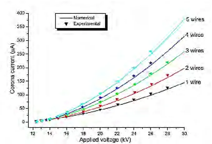
Figure 2.2 Current-Voltage characteristics for different number of wires 11 Figure 2.3 Two types of ESP (a)Parallel plate (b) Tubular 12
Figure 2.4 Shape of electrodes 14
Figure 2.5 Electrode shape 15
Figure 2.6 Cross-section of the coaxial corona reactor 16
Figure 3.1 Flowchart of project 17
Figure 3.2 Design of the chamber 18
Figure 3.3 View from each side of the prototype 18
Figure 3.4 Different sizes of cable 19
Figure 3.5 Aluminium plate 20
Figure 3.6 Two types of dust that are sawdust and ash 20
Figure 3.7 Acrylic box 21
Figure 3.8 High Voltage Amplifier Trek 22
Figure 3.9 DC Power Supply 22
Figure 3.10 Set-up of the experiment 23
Figure 3.11 Process to collect the data 24
viii
Figure 4.3 Periodic Table 28
1
CHAPTER 1
INTRODUCTION
1.1 Motivation
In order to prevent air pollution due to industrial activity, engineers had developed a device to control air pollution known as electrostatic precipitator. This device very helpful to increase air quality and fulfil the requirement for air quality index. In an electrostatic precipitator, a static charge attracts contamination particles to electrified plates of metal, similar to how static electricity in clothing attracts bits of lint. This method works very well for power plant area, cement factory and dusty area.
Furthermore, quality of air nowadays also affected by the pollution of vehicles and haze. Thus, indoor air quality also polluted. Polluted air is harmful to health such as lung problem. In order to keep the indoor air quality clean, the development of chamber for dust particles based on electrostatic concept which has same principle as electrostatic precipitator is done in this project.
1.2 Project Background
2
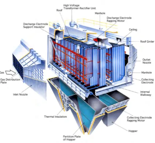
Figure 1.1: Electrostatic Precipitator
Basic principle of this device is, when dc high voltage is supply to the electrode, corona effect will ionize the surrounding atmosphere. Particles that enter the chamber will collide with the free electrons and form charged particles (ions). This charged particles move toward the collecting plate due to electrostatic force.
Figure 1.2: Basic Concept of Electrostatic Dust Collector
[image:13.595.77.525.473.659.2]3
found in air especially for the area which is near to the coal-fired power plants. Example of toxic metals are Arsenic(As), Nickel(Ni), Mercury(Hg), Strontium(Sr), Selenium(Se) and Beryllium(Be)[1].
It is important to have a good air quality especially in office or home where the human being spend time mostly. Polluted air can cause a lot of disease to people such as lung cancer, asthma and lung dysfunctions. Thus, the indoor air quality need to be concern. Electrostatic dust collector can help us to improve indoor air quality.
1.3 Problem Statement
Clean air is important for human being to ensure the healthy life. Dust will make the quality of air decreases. Small particle in air cannot be seen with our eyes due the size which is very small and light. Building and road construction near to our living area cause a lot of dust. Residential area which are located near to the industrial area also face the air pollution problem. Therefore, a lot of research have been done to produce a product which can collect dust and small particle in air. One of the solution is by using electrostatic concept. Electrostatic dust collector can trap particle which is smaller than 5 µm compare to the other air filter. Thus, the research about this concept will be conducted and the best design will be suggested as a product for control indoor air quality.
1.4 Objectives
The objectives of this project are:
i. To design and develop dust or particle collector chamber based on electrostatic concept ii. to analyse the effect of size and type of dust to the efficiency of electrostatic dust
collector
iii. To investigate the effect of size of cables to the efficiency of electrostatic dust collector iv. To compare the effect of different supply voltage to the efficiency of electrostatic dust
4
1.5 Scope
The focus of this project is to increase the indoor air quality. The scope of this project is to design electrostatic chamber to collect dust or ultrafine particle. This project consists of discharge electrode and collecting plate. The space between the electrode and collecting plate are important to study to prevent breakdown. Spacing 5 cm is tested in this project. Different size of cables is tested to see the effect to the collection efficiency. Size of cable used are 1.0, 2.5, 4.0, 6.0 and 10 mm2. Two type of dust, sawdust and ash with different size will be tested
5
CHAPTER 2
LITERATURE REVIEW
2.1 Introduction
Rigorous new regulations in dust emission by power plants and industrial processes have brought new requests for dust control devices. These new regulations will require most extreme molecule outflows on the level of 10–50 mg/Nm3 and confinements to the discharge
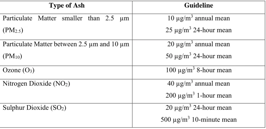
[image:16.595.73.534.347.571.2]of fine particles smaller than 2.5 mm. To meet these necessities, new techniques for gas cleaning with collection efficiency higher than 99% have been designed and tested [2]. Table 2.1 show the air quality guideline by the World Health Organization (WHO) [3].
Table 2.1: Guideline by WHO
Type of Ash Guideline
Particulate Matter smaller than 2.5 µm (PM2.5)
10 µg/m3 annual mean
25 µg/m3 24-hour mean
Particulate Matter between 2.5 µm and 10 µm (PM10)
20 µg/m3 annual mean
50 µg/m3 24-hour mean
Ozone (O3) 100 µg/m3 8-hour mean
Nitrogen Dioxide (NO2) 40 µg/m3 annual mean
200 µg/m3 1-hour mean
Sulphur Dioxide (SO2) 20 µg/m3 24-hour mean
500 µg/m3 10-minute mean
6
ESP is utilized to remove contaminations from large gas flow (hundreds of thousands m3/h). The efficiency of ESP’s relies upon voltages waveform and amplitude, type of power
supply, current control, geometry of electrostatic precipitators, type of discharge wires, gas composition, particles distribution, gas flow, temperature, gas pressure and particles velocities distribution [5].
The basic operation of the ESP is that the gas particle will passes through an electric field and will be ionized. Then, the charged particle will diverted over the electric field to relocate and be deposited on the collecting plate [6].
2.2 Ionization Process
Ionization is one of the important process in Electrostatic Precipitator. The particle that enter ESP will be charged and produced ion. Generally, the particle that enter ESP will pass through strong electric field and accelerated rapidly and attains a high velocity. When this particle collides with stray electron from any variety of sources, it has enough energy to knock one or more electron loose from its shell, so the particle (gas molecule) will ionize [7].
Ionization is a process of freeing an electron from a gas atom with the simultaneous production of a positive ion. Mechanism of ionization can be categorised to ionization by collision, photo-ionization, secondary ionization process. Gas becomes a conductor when a high-voltage is applied between the two electrodes immersed in a gaseous medium and an electrical breakdown occurs [8].
2.2.1 Ionization by Collision
During the ionization by collision, number of new electron and positive ion increasing when a free electron collides with a neutral gas atom.
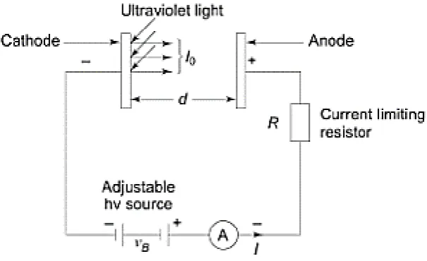
Based on Figure 2.1, when electric field E is applied across two plane parallel electrodes
7
𝑒 −+ 𝐴 ɛ >𝑉𝑖 → 𝑒 −+ 𝐴++ 𝑒 − (2.1)
[image:18.595.171.474.161.346.2]where, A is the Atom, A+ is the positive ion and e- is the electron.
Figure 2.1: Arrangement for study of a Townsend discharge
A few of electrons produced at the cathode by some external means ionize neutral gas particles and producing positive ions and more free electrons. The electron then makes ionizing collision themselves thus increasing the number of electrons. Then, the process will repeat itself.
2.2.2 Photo-ionization
Photo-ionization happen when the amount of radiation energy consumed by an atom surpasses the ionization potential [8]. Process which radiation can be consumed by atom or molecule are:
a) excitation of the molecule to a higher energy state
b) continuous absorption by direct excitation of the particle or separation of diatomic molecule or direct ionization.
8
ℎ𝑣 + 𝐴 ↔ 𝐴∗ (2.2)
Ionization occurs when
𝜆 ≤ 𝑐 .ℎ
𝑉𝑖 (2.3)
where;
h = Planck’s constant c = velocity of light
𝜆 = the wavelength of the incident radiation
Vi = ionization energy of molecule
Based on the equation, the greater ionization energy, the shorter the wavelength of the radiation capable of causing ionization. It was shown experimentally that a radiation having a wavelength of 1250A is equipped for creating photo-ionization of practically gasses.
2.2.3 Secondary Ionization Process
Secondary ionization process is the process of producing secondary ionization which sustain a discharge due ionization by collision and photo-ionization. It can be classified into three section.
a) Electron Emission due to Positive Ion Impact
Positive ion is formed due to ionization by collision or photo-ionization. Emission of electron from the cathode causes by approaching of the positive ion to a metallic cathode by giving up its kinetic energy on impact. If the total of kinetic energy plus with ionization energy is greater than twice the work function of metal, an electron will be ejected and the ion will be neutralised by the second electron. This probability depends on the material of electrode and kind of gas used.
b) Electron Emission due to Photons
9
ℎ . 𝑣 ≥ 𝜑 (2.4)
where
φ = the work function of the metallic electrode
The relationship of the frequency (v) known as threshold frequency is expressed by:
𝑣 = 𝜑
ℎ (2.5)
If the incident radiation has a greater frequency than the threshold frequency, then the excess energy goes partly as the kinetic energy of the emitted electron and partly to heat the surface of electrode.
c) Electron Emission due to Metastable and Neutral Atoms
Metastable atom is the particle have longer lifetime (10-3 s) than ordinary particle (10-8 s).
Impact of excited (metastable) atoms will eject electron from the metal surface by provided energy that sufficient to overcome work function. The most easily method to observe this process is with metastable atom due to its lifetime. In the ground state, neutral atoms give rise to secondary electron emission if their kinetic energy is high (≈ 1000 eV).
2.2.4 Electron Attachment Process
Electron attachment process is the process that form negative ion by the collision which electron will attached to atom. The energy of the electron and the nature of the gas is the important factor for this process. All the insulation gases such as O2, CO2, Cl2, F2, C2F6, C3F8,
C4F10, CCl2F2 and SF6 have this property. Electron attachment process can be presented as:
𝐴𝑡𝑜𝑚 + 𝑒 −+ 𝑘 → 𝑛𝑒𝑔𝑎𝑡ive atomicion + (𝐸𝑎+ K) (2.6)
Ea = Electron affinity
K = Kinetic energy
10
2.3 Corona Discharge
Corona discharge is a discharge in the gas to appear at points with highest electric field intensity, namely at sharp points or where the electrodes are curved or on transmission lines when there is increase in voltage in non-uniform electric field. This type of discharge will ensure production of electron in ESPs so that ionization process occur.
In ESPs, generation of corona occur between the parallel electrode, which is connected to a dc high-voltage supply, and the grounded outer electrode [9]. Ions produced in the discharge will charging the particle are subsequently accelerated by the electric field forces toward the outer electrode. The process of electrostatic precipitation relies on upon this movement of the charged particles toward the collector electrode.
Non- uniform electrical field is required to produce corona discharge generation in the air at atmospheric conditions, which can be achieved by using a small diameter wire electrode, energized from a high-voltage supply, and a metallic plate or cylinder, connected to the ground, which is designated as collecting electrode. In order to improve the air quality and to reduce the emissions of smoke, fumes, and dust, industrial ESPs are used [6].
The voltage-current characteristics of a corona discharge [10] normally presented as
𝐼 = 𝐴𝑉 (𝑉 − 𝑉𝑐) (2.7)
Where:
A is a constant,
V = the corona starting voltage I = the electric current
V = the applied voltage
11
[image:22.595.146.486.244.475.2]Ahmed Kasdi[11] had been conducted an experiment about “Computation and measurement of corona current density and V-I characteristics in wires-to-plates electrostatic precipitator”. The researcher used different configuration of electrode in order to test electrostatic precipitator performance. From this experiment, few results were obtained. For the same applied voltage, as the quantity of wire used increases the collected current increases too. This is due to increasing of discharge electrode. For the same voltage, the corona discharged current increases significantly with the augmentation of the wire-to-wire spacing. This is due to the shielding effect exerted by each wire on the other.
Figure 2.2: Current-Voltage characteristics for different number of wires
2.4 Operational Properties of ESP
Electrical energy is required for particle charging, gas ionization, particle coagulation or vapour condensation [2]. The overall collection efficiency of any cleaning device can be determined from the formula:
𝜂 = 𝑚𝑜𝑢𝑡 𝑚𝑖𝑛
(2.8)
12
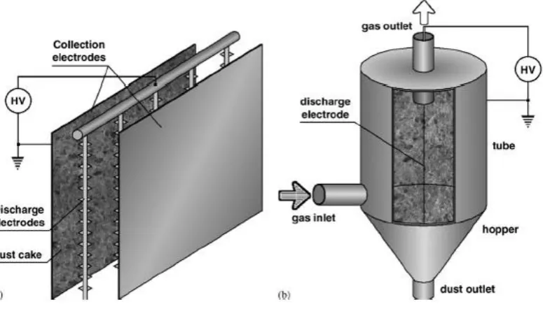
Figure 2.3: Two types of ESP (a)Parallel plate (b) Tubular
The charging particles mechanism which are most important consist of:
a) Field charging. Ions are headed to the molecule because of electrostatic force caused
by an external electric field. This force is adjusted by the repulsive force of the charge granted to the particle.
b) Diffusion charging. This is because of the kinetic energy of gaseous ions that bombard
the molecule independently of the electric field.
Field charging is the dominant mechanism for particle larger than 1µm while the ion diffusion is dominant for particle smaller than 0.1µm.
The current density on the collection electrode is usually in range of 0.1-1mA/m2 and
the energy consumption is usually the order of 0.3-108MW/1000 N m3 [2].The collection
efficiency of an ESP can be estimated from the Deustch formula:
𝜂 = 1 − 𝑒−𝑉𝑚𝐴/𝑉 (2.9)
vm = the mean migration velocity of the particle across the precipitator
13
From this formula, the migration velocity or cross-sectional area will increase by increasing the distance between the plates or decreasing the gas flow rate.
2.5 Gap between Plate of ESP
[image:24.595.72.525.352.618.2]Theoretically, the smaller spacing between the parallel plate, the higher the current density at the same operational voltage. There is no exact relationship between the current density at collecting plate and efficiency of ESP was found [12]. The wider space between plate is used to increase overall collection efficiency. The optimum electrode spacing is between 400 to 600mm. on the other hand, there was no strong evidence for that assumption [2]. The upper limit of this distance is difficult to predict. Table 2.2 explained about the plate spacing can be divided.
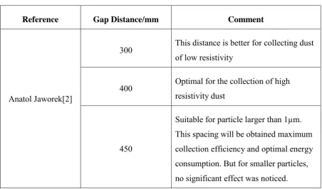
Table 2.2: Comparison of Plate Spacing
Reference Gap Distance/mm Comment
Anatol Jaworek[2]
300 This distance is better for collecting dust of low resistivity
400 Optimal for the collection of high resistivity dust
450
Suitable for particle larger than 1µm. This spacing will be obtained maximum collection efficiency and optimal energy consumption. But for smaller particles, no significant effect was noticed.