Int. J. Electrochem. Sci., 8 (2013) 548 - 563
International Journal of
ELECTROCHEMICAL
SCIENCE
www.electrochemsci.org
Influence of the Cerium Concentration on the Corrosion
Performance of Ce-doped Silica Hybrid Coatings on Hot Dip
Galvanized Steel Substrates
Roohangiz Zandi Zand1, Kim Verbeken2, Annemie Adriaens1,* 1
Department of Analytical Chemistry, Ghent University, Krijgslaan 281-S12, B-9000, Ghent, Belgium 2
Department of Materials Science and Engineering, Ghent University, Technologiepark 903, B-9052 Zwijnaarde (Ghent), Belgium
*
E-mail: [email protected]
Received: 22 October 2012 / Accepted: 24 November 2012 / Published: 1 January 2013
The aim of this work was to investigate the effect of the cerium concentration on the morphology and anticorrosion performance of cerium–silane hybrid coatings on hot dip galvanized (HDG) steel substrates. 3-glycidoxypropyltrimethoxysilane (GPTMS) and bisphenol A (BPA) were employed as precursors to prepare the sol–gel based silane coating. Cerium nitrate hexahydrate was added to the silane coatings as dopant in five different concentrations. The morphology of the coatings before and after the corrosion test was examined by scanning electron microscopy (SEM), indicating an effect of the cerium concentration. Very low and very high cerium concentrations deteriorate the corrosion inhibition in the sol-gel matrix and consequently, there is an optimum concentration of cerium nitrate. Accelerated salt spray testing showed that corrosion near an artificial scratch is blocked efficiently by high cerium nitrate contents, whereas uniform corrosion is inhibited effectively with comparatively low ceria contents. Electrochemical studies indicate a general beneficial effect of the incorporation of cerium nitrate, although the performance of the coated substrate depends on the cerium nitrate content. The results of electrochemical impedance spectroscopy (EIS) and electrochemical polarization confirmed that the corrosion resistance of the coatings initially increases and then decreases as the cerium concentration goes up. Optimal corrosion resistance was obtained at a cerium concentration of 0.05 M.
Keywords: Galvanised steel; Dopant concentration; Corrosion protection; Cerium nitrate; Sol-gel coating.
1. INTRODUCTION
[1]. Chromate coatings provide an excellent protection against corrosion. However, the widely used Cr compounds have been banned in Europe since 2007 and soon worldwide due to their highly carcinogenic effect [2-3].
For this reason, research has focused towards the development of green alternative coatings [4]. Lanthanide ions, such as Ce3+, Y3+, La3+, Pr3+, Nd3+, seem to fulfil the basic requirements as alternative corrosion inhibitors [5]. These elements form insoluble hydroxides and have a low toxicity [4-5]. In addition, lanthanides are economically competitive products, since some of them in particular cerium are relatively abundant in nature [4, 6- 7].
Cerium doped sol–gel coatings are actively investigated for the surface pre-treatment of metals and alloys. Positive results have been obtained with aluminium and its alloys [8–11], magnesium and its alloys [12-13] and steel [5, 14–18]. Similar as pure sol–gel coatings, the cerium doped ones can also form a dense barrier, which hinders the penetration of electrolyte towards the metal surface. The important difference between them is that cerium doped sol–gel coatings display self-healing abilities, which can automatically repair the damaged areas, providing a long-term corrosion protection [1].
Also cerium–silica hybrid coatings have been investigated as prospective pre-treatments for many metallic substrates. For instance, Trabelsi [19] and Zhong et al. [1] studied the electrochemical behaviour of Ce-doped silane hybrid coatings on galvanized steel and magnesium alloy AZ91D, respectively. They found that the protective behaviour of the pre-treatments based on Ce-doped silane solutions depends on the dopant concentration. The results also suggest that there is an optimum concentration of dopant as higher or lower concentrations lead to a negative effect in the coating barrier properties. Villegas and co-workers [20] investigated the electrochemical properties of cerium– silica sol–gel thin films on zinc panels. They found that the critical concentration of the anticorrosive pigment (Ce3+ salts) was in the 0.2–0.6 range (wt.%). Above this concentration, defects were observed in the sol–gel film. Aparicio and co-workers [8] studied the effects of Ce-containing sol–gel coatings reinforced with SiO2 nanoparticles on the protection of AA2024. The results show that the incorporation of cerium ions in the coating induced an inhibition action. However, the interaction of the cerium pigments with the silica network usually leads to significant shortcomings in the coating stability and the activities of the cerium pigments [2]. Therefore, the cerium concentration has to be carefully controlled to overcome these shortcomings as much as possible.
2. EXPERIMENTAL
2.1. Sample preparation
The silane solution was prepared by adding 4.084 mL of 3-glicidoxypropyltrimethoxy silane or GPTMS (Merck) to 0.5 mL of HCl-acidified water (pH = 2) (H2O/Si mole ratio = 0.5 [22]). The solution was placed in a sealed beaker and stirred at room temperature for 20 min at a rate of 240 rpm to hydrolyse and condensate the silane precursors. Ce(NO3)3.6H2O (Fluka) was used as cerium source and was added at the end of this step of synthesis, followed by stirring for 10 min. The Ce/Si mole ratio was 0.000, 0.001, 0.005, 0.010, 0.050 and 0.100, respectively. In a following step, 2.111 g of bisphenol A (BPA) (Merck) was added to the solutions as a cross-linking agent (BPA/Si mole ratio = 0.5). The latter has shown to have a significant effect on the morphology and corrosion resistance of the coating [5]. BPA was dissolved by mixing the solution for 80 minutes. To accelerate the condensation reaction, 0.0152 mL of 1-methylimidazol (MI) (Merck) (MI/Si mole ratio = 0.01) was added to the solution, followed by stirring for 5 min. The result was a clear and colourless homogenous solution.
The metallic substrate consisted of hot dip galvanized steel coupons (4.98 cm2 area and 0.1 cm thickness for the SEM measurements and electrochemical tests) and plates (7 cm × 15 cm × 0.1 cm for the salt spray tests). The zinc coating has a weight of approximately 140 g/m2 and a thickness of approximately 10 µm. The galvanized steel specimens were degreased using an alkaline cleaner. Following the cleaning, the substrates were washed with distilled water, dried in air and immersed in the silane solution for 60 s. The coated specimens were dried at room temperature for 24 hours and subsequently submitted to a 25-130 °C curing process for 90 minutes to initiate extensive cross-linking in the hybrid films [17]. The coating thickness was measured by profilometry (Check line 3000 pro, Germany).
2.2. Analytical methods
Scanning electron microscopy (SEM) measurements were performed with a XL30 SEM microscope (FEI). The aim was to characterize the surface morphology of the coated substrates before and after 144 hours immersion in a 3.5 % NaCl solution. Secondary electron images were collected at 15 kV.
The corrosion performance of the coated substrates was evaluated in a neutral salt spray test, following the ASTM B117 procedure [23] by employing a 5 % NaCl solution. Prior to exposure, the back and the edges of the plates were covered with adhesive tape. An artificial scratch was made in the coating that reached the substrate to examine possible delamination. Visual assessment of the macroscopic surfaces was carried out at various time intervals during the total exposure time (336 hours).
analyzer module. A three-electrode system was used, in which a Ag/AgCl KClsat electrode, a platinum mesh electrode and the sample were used as reference, counter, and working electrodes, respectively. The EIS measurements were performed at the open circuit potential. The data were obtained as a function of frequency (frequency range of 105 Hz to 10-2 Hz), using a sine wave of 10 mV amplitude peak to peak. All EIS measurements were carried out at room temperature and the samples were immersed in the electrolyte solution 30 min before the data were acquired and measurements were performed periodically. For each experiment, measurements were repeated four times. Impedance fitting was performed using the appropriate equivalent circuits by means of Z-view software (Scribner Associates Inc.).
The potentiodynamic measurements were taken within the range of -1500 to 1000 mV versus Ag/AgCl KClsat at a rate of 1 mV/s. Also here measurements were performed four times. The Tafel extrapolation method (conducted according to the ASTM Standard G3-89, 2004) [24] was utilized for determining Icorr and Ecorr.
3. RESULTS AND DISCUSSION
3.1. Surface morphology before and after the corrosion test
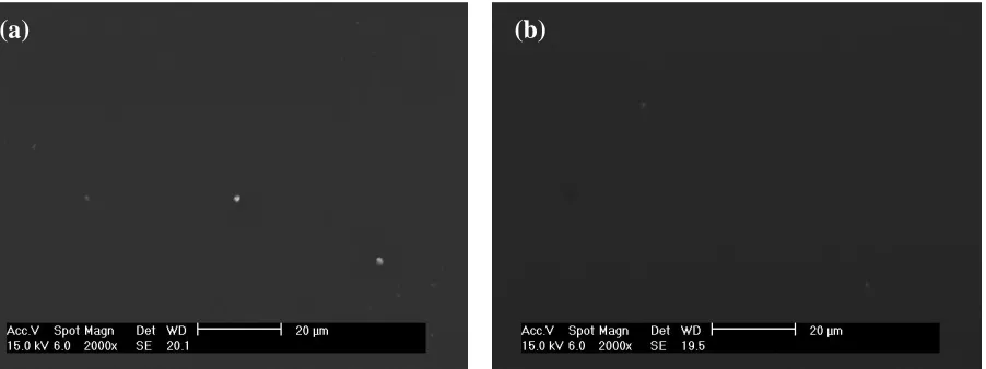
Figure 1 shows that the microstructural features before the corrosion test of the non-doped and the 0.05 M cerium doped silica coatings reveal a smooth surface without any cracks nor defects. However, several agglomerations appear in the coating matrix of the silica coating without any Ce (Figure 1a), which may be ascribed to the relatively high viscosity of the sol [1]. The heterogeneities in the coating might provoke regions more prone to corrosion.
Figure 1. Scanning electron micrographs of cerium-silica coatings doped with (a) 0.000 M and (b) 0.05 M cerium nitrate on HDG steel samples prior to immersion in a 3.5% NaCl solution.
[image:4.596.79.530.503.672.2]
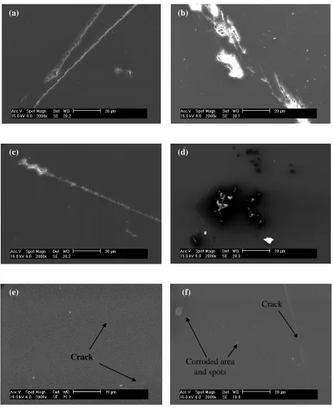
Figure 2. Scanning electron micrographs of cerium-silica coatings doped with (a) 0.000 M , (b) 0.001 M, (c) 0.005 M, (d) 0.01 M, (e) 0.05 M and (f) 0.1 M cerium nitrate on HDG steel samples after 144 hours immersion in 3.5% NaCl solution.
After 72 hours of immersion in a 3.5 % NaCl solution, localized corrosion is observed for all coatings (except for the 0.050 M sample), consisting of an exfoliation of the corrosion products and cracks of different sizes. These localized attacks promote the hybrid film deterioration and
(a) (b)
(c) (d)
(e) (f)
Crack
Crack
delamination, and is possibly due to hydrolysis reactions at the interface. Additionally, the diffusion of the oxidant ions speeds up and the corrosion rate increases causing an accumulation of corrosion products at the interface, at the same time promoting the formation of defects and micro-cracks.
The coating prepared using 0.050 M cerium nitrate still appears homogenous and crack-free after 120 hours of immersion (not shown). Upon increasing the immersion time to 144 hours, however, cracks started to appear in the coating. For comparison, images of specimens after 144 hours immersion are shown in Figure 2. Based on these observations it seems that very low and very high concentrations of cerium lead to a lack of corrosion inhibition in the sol-gel matrix and consequently to a weak inhibition efficiency.
3.2. Performance in the salt spray test
The sol–gel coated substrate without any cerium nitrate (average coating thickness: 2.7 + 0.2 µm) showed limited resistance in the neutral salt spray test. Corrosion was visible to the naked eye already after an exposure of 120 hours. Corrosion of the sol–gel coated substrates with 0.005 and 0.010 M cerium nitrate (average coating thickness: 5.5 + 0.2 and 7.6 + 0.2 µm, respectively) was detected after 168 hours, while for the coatings containing 0.001 and 0.100 M cerium nitrate (average coating thickness: 6.4 + 0.2 and 11.5 + 0.2 µm, respectively), the corrosion was evident after 240 hours. The best performance in the salt spray test, with respect to general and localized corrosion, was shown for the sol–gel coated substrate containing 0.050 M cerium nitrate (average coating thickness: 8.4 + 0.2 µm). Here corrosion was detected after 336 hours of exposure.
For the sol-gel coated substrate without any cerium nitrate, delamination increased rapidly with exposure time to the salt spray. With incorporation of cerium nitrate, delamination again increased with exposure time but with markedly reduced rates; for example, with 0.001 and 0.050 M cerium nitrate, comparatively little delamination was observed after exposure to the neutral salt spray for 336 h. For comparison, images of specimens after salt spray testing for 336 hours are shown in Figure 3.
The different corrosion behaviour of the five samples containing cerium nitrate can be explained by a model of a hybrid network with a limited capacity for the inhibitor uptake. A low concentration of inhibiting cerium nitrate leads to improved barrier properties and, therefore, to an improved uniform corrosion protection. Addition of an increased content of cerium nitrate to the coating leads to an increased porosity. This porosity reduces the barrier properties of the coating and the protection offered to the substrate is reduced [15, 20, 25-26].
Figure 3. Photographs of cerium-silica coatings doped with (a) 0.000 M, (b) 0.001 M, (c) 0.005 M, (d) 0.01 M, (e) 0.05 M and (f) 0.1 M cerium nitrate on HDG steel samples after 336 hours of salt spray exposure.
3.3. Electrochemical impedance spectroscopy
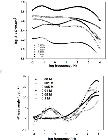
Figures 4a shows the impedance spectra obtained on the six hot dip galvanized steel coated samples after 24 hours of immersion in a 3.5 % NaCl solution. The impedance value at low
(b)
(c) (d)
(e) (f)
(a)
frequencies (LF) initially increases when the cerium nitrate concentration increases from 0.000 to 0.050 M. Above this critical concentration, a gradual fall in the impedance value at LF with increase in cerium concentration up to 0.100 M is recorded.
(a)
(b)
[image:8.596.92.467.154.642.2]
The shape of the phase angle plot in figure 4b indicates the presence of two time constants, which can be attributed to the response of the silane film (high frequency process) and to the response of the processes occurring at the silane film/substrate interface (low frequency time constant).
(a)
(b)
[image:9.596.84.487.146.707.2]
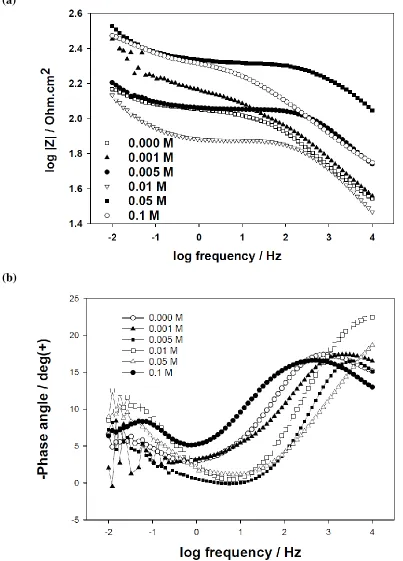
As a comparison, the EIS bode modulus and phase angle spectra of the various coatings after 144 hours of immersion in a 3.5% NaCl solution are presented in Figure 5a and b, respectively. It is clear that a significant decrease of the impedance value at LF for all samples is observed. This can be attributed to the hydrolytic degradation of the coatings. The impedance value at LF of coatings doped with various concentrations (except 0.05 M) of cerium nitrate drops to less than 300 Ω cm2. However, for the coating doped with 0.05 M cerium nitrate, the impedance value at LF is still as high as 337 Ω cm2. Therefore, the dependence of the corrosion resistance on the cerium concentration indicates that it is very significant to control the cerium concentration when aiming for a cerium – silica coating with optimal corrosion resistance [2, 19].
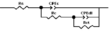
[image:10.596.204.431.394.459.2]The interpretation of the EIS results can be made by numerical fitting, using the equivalent circuit depicted in Figure 6. In this equivalent circuit, constant phase elements were used instead of pure capacitors due to the non-ideal character of the corresponding response with phase shifts differing from -90°. The true capacitances were then calculated from the respective CPE parameters as described elsewhere [5]. Thus, for the equivalent circuit of Figure 6, Rs is resistance of the electrolyte; CPEC and RC represent the capacitance and resistance of the hybrid coating, respectively; CPEdl is the capacitance of electrochemical double layer at the metal/electrolyte interface and Rct is the charge transfer resistance of the metal.
Figure 6. The equivalent circuit used for numerical fitting of the EIS data during immersion in a 3.5% NaCl solution.
(a)
(b)
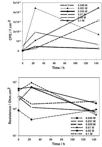
Figure 7. Evolution of the coating capacitance (a) and coating resistance (b) during immersion in a 3.5% NaCl solution. Values were obtained by numerical fitting using the equivalent circuit depicted in figure 6.
[image:11.596.121.470.85.552.2]
fast decrease is related to the formation of new defects and pores in the coatings [26]. The evolution of the coating resistance and coating capacitance suggests that there is an optimum concentration of cerium nitrate for doping of the silane solutions [19].
(a)
(b)
Figure 8. Evolution of the charge transfer resistance (a) and double layer capacitance (b) during immersion in a 3.5% NaCl solution. Values were obtained by numerical fitting using the equivalent circuit depicted in figure 6.
[image:12.596.140.468.152.624.2]
(Figure 8(a)). Beyond this critical concentration, a significant fall in the charge transfer resistance value is observed. The resistance of all coatings decreases during 144 hours of immersion and the highest resistances are observed for the coating doped with 0.050 M cerium nitrate. This behaviour is a consequence of the good resistance of the doped coating against the onset of the corrosion process [19].
The double layer capacitance (Figure 8(b)) of all coatings increases as a function of immersion time. The EIS results also show that the coatings doped with 0.000 and 0.001 M cerium nitrate develop a corrosion activity earlier than the other coatings. The first signs of corrosion activity in the substrate pre-treated with 0.000 and 0.001 M cerium nitrate were detected after 24 h of immersion, whereas for the others coatings (except for the one containing 0.05 M cerium nitrate) corrosion started after 96 hours of immersion. These results are in good agreement with the evolution of the coating resistance and indicate that there is an optimum concentration of cerium in the silane solution. For the highest concentration of cerium nitrate, there is a negative effect on the barrier properties of the coating, facilitating corrosion activity [19].
3.4. Potentiondynamic polarization results
[image:13.596.89.508.372.683.2]
Potentiodynamic polarization measurements were carried out to estimate the effect of the cerium concentration on the corrosion resistance of hybrid coatings and the corresponding curves are shown in Figure 9. The corrosion current (icorr) and corrosion potential (Ecorr) were determined by Tafel extrapolation [1, 24]. The relevant parameters (Table 1) indicate the different effects of the cerium concentration on the icorr and Ecorr of hybrid coatings. There are two noticeable difference in the curve's features for samples that do not contain any cerium nitrate and the one containing 0.050 M cerium nitrate. One is a large shift in the Ecorr value to a less negative value and the other one is related to a marked reduction of cathodic current density (A/cm2). The difference in Ecorr directly reflects the degree of coverage of the coating over the entire substrate [27]. The good coverage provides a continuous nano-porous coating layer and causes the shift of the Ecorr value to a more positive value. The difference in cathodic current density is attributed to the inhibiting aspect of the cathodic reaction at the corrosion site, particularly the oxygen reduction reaction [27, 28]. A similar behaviour has been reported by Zhong et al. [1] for the magnesium alloy AZ91D in a 3.5 % NaCl solution after the addition of cerium nitrate. According to their results, Ce3+ ions react in a first stage with the OH− ions, which are generated in the cathodic zones of alloy, giving place to the formation of the islands rich in cerium. Those involve a blocking of the cathodic sites reflected by a reduction in the corrosion speed. Hence, such a reaction, which leads to the corrosion of steel, appears to be retarded by depositing a silica coating containing 0.05 M cerium nitrate as inhibitor.
Table 1. Summary of the electrochemical parameters obtained from the polarization measured in a 3.5 % NaCl solution.
sample Ecorr (V) Icorr (A cm-2) bc (V/dec) ba (V/dec) Passive area (V)
0.000 M -0.974 3.577 × 10⁻⁵ 0.06 0.093 -0.792 to -0.241
0.001 M -1.025 3.484 × 10⁻⁶ 0.043 0.057 -0.815 to -0.348
0.005 M -0.972 1.184 × 10⁻⁶ 0.017 0.066 -0.829 to -0.320
0.01 M -0.963 6.013 × 10⁻⁶ 0.014 0.027 -0.838 to -0.341
0.05 M -0.957 1.749 × 10⁻⁶ 0.047 0.0096 -0.864 to -0.289
0.1 M -0.976 1.020 × 10⁻⁶ 0.016 0.027 -0.840 to -0.304
4. CONCLUSIONS
[image:14.596.57.536.472.579.2]
corrosion near the artificial scratch and uniform corrosion, compared to the silane coating without cerium nitrate.
Upon addition of cerium nitrate as dopant, the silane coating shows improved barrier properties, coating resistance and a decrease in coating capacitance. Incorporation of 0.05 M cerium nitrate reduces the cathodic current density by two orders of magnitude and shifts the voltage to more positive values compared with the non-doped silane coated substrate during polarization in a 3.5 % NaCl solution.
ACKNOWLEDGEMENTS
The authors wish to acknowledge Ghent University for financial support of this study. The authors would also like to thank Michel Moors and Christa Sonck for their technical assistance.
References
1. X. Zhong, Q. Li, J. Hu, X .Yang, F. Luo, Y. Dai, Prog. Org. Coat, 69 (2010) 52.
2. M.L. Zheludkevich, D.G. Shchukin, K.A. Yasakau, H. Möhwald, M.G.S. Ferreira, Chem. Mater, 19 (2007) 402.
3. D.G. Shchukin, M. Zheludkevich, K. Yasakau, S. Lamaka, M.G.S. Ferreira, H. Möhwald, Adv. Mate, 18 (2006) 1672.
4. N.C.R. Navarro, L. Paussa, F. Andreatta, Y. Castro, A. Durán, M. Aparicio, L. Fedrizzi, Prog. Org. Coat, 69 (2010) 167.
5. R. Zandi Zand, K. Verbeken, A. Adriaens, Prog. Org. Coat, 75 (2012) 463. 6. N. Pirhady Tavandashti, S. Sanjabi, Prog. Org. Coat, 69 (2010) 384.
7. A. Nazeri, P.P. Trzaskoma-Paulette, D. Bauer, J. Sol-Gel. Sci. Techn, 10 (1997) 317. 8. N.C. Rosero-Navarro, S.A. Pellice, A. Durán, M. Aparicio, Corros. Sci, 50 (2008) 1283. 9. K.A. Yasakau, M.L. Zheludkevich, O.V. Karavai, M.G.S. Ferreira, Prog. Org. Coat, 63 (2008)
352.
10. M.L. Zheludkevich, R. Serra, M.F. Montemor, K.A. Yasakau, I.M.M. Salvado, M.G.S. Ferreira, Electrochim. Acta, 51 (2005) 208.
11. A. Pepe, M. Aparicio, S. Cerć, A. Durán, J. Non-Cryst. Solids, 348 (2004) 162. 12. M.F. Montemor, M.G.S. Ferreira, Prog. Org. Coat, 60 (2007) 228.
13. M.F. Montemor, M.G.S. Ferreira, Electrochim. Acta, 52 (2007) 7486. 14. H. Wang, R. Akid, Corros. Sci, 50 (2008) 1142.
15. A. Phanasgaonkar, V.S. Raja, Surf. Coat. Technol, 203 (2009) 2260.
16. A.M. Cabral, W. Trabelsi, R. Serra, M.F. Montemor, M.L. Zheludkevich, M.G.S. Ferreira, Corros. Sci, 48 (2006) 3740.
17. R. Zandi Zand, K. Verbeken, A. Adriaens, Prog. Org. Coat, 72 (2011) 709. 18. R. Zandi Zand, K. Verbeken, A. Adriaens, Int. J. Electrochem. Sci, 7 (2012) 9592.
19. W. Trabelsi, P. Cecilio, M.G.S. Ferreira, M.F. Montemor, Prog. Org. Coat, 54 (2005) 276. 20. M. Garcia-Heras, A. Jimenez-Morales, B. Casal, J.C. Galvan, S. Radzki, M.A. Villegas, J. Alloy.
Compd, 380 (2004) 219.
21. N.C.R. Navarro, P. Figiel, R. Jedrzejewski, A. Biedunkiewicz, Y. Castro, M. Aparicio, S.A. Pellice, A. Dura´n, J. Sol-Gel. Sci. Technol, 54 (2010) 301.
22. R.Z. Zand, Investigation of corrosion, abrasion and weathering resistance in hybrid nanocomposite coatings based on epoxy-silica, Thesis, Azad University-Tehran North Branch, (2005).
24. ASTM Standards for Corrosion Testing of Metals: 3rd Edition, ASTM International, W. Conshohocken, PA, (2008).
25. J. Ballarre, E. Jimenez-Pique, M. Anglada, S. A. Pellice , A. L. Cavalieri, Surf. Coat. Technol, 203 (2009) 3325.
26. M. Schem, T. Schmidt, J. Gerwann, M. Wittmar, M. Veith, G.E. Thompson, I.S. Molchan, T. Hashimoto, P. Skeldon, A.R. Phani, S. Santucci, M.L. Zheludkevich, Corros. Sci, 51 (2009) 2304. 27. T. Sugama, JCT Res., 2 (2005) 649.
28. M. Hosseini, H. Ashassi-Sorkhabi, H. Yaghobkhani Ghiasvand, J. Rare Earth, 25 (2007) 537.