Int. J. Electrochem. Sci., 11 (2016) 5983 – 5998, doi: 10.20964/2016.07.06
International Journal of
ELECTROCHEMICAL
SCIENCE
www.electrochemsci.org
Electrochemical Corrosion and Wear Behavior of an Ultra-thin
DLC Film Deposited on Different Annealing Ni-P Layers on
Al-Mg Alloy in NaCl Solution
Cheng-Kuo Lee, Ching-Hung Chen, An-Hung Tan
Department of Mechanical Engineering, Chien Hsin University of Science and Technology, Chung-Li 32097, Taiwan, R.O.C.
*
E-mail: cklee@uch.edu.tw
Received: 26 March 2016 / Accepted: 8 May 2016 / Published: 4 June 2016
This study evaluated the electrochemical corrosion and wear behavior of an ultra-thin diamond-like carbon film on various annealing electroless Ni-P coatings on an Al-Mg alloy media plank in 3.5wt.% NaCl solution. The annealing process was performed at different temperatures from 230˚C to 280˚C. The results indicated that annealing increased the hardness of electroless Ni-P coatings to an extent that increased with annealing temperature by causing the precipitation of Ni3P, and this further resulting that the electrochemical corrosion resistance of electroless Ni-P coatings fell as the annealing temperature increased. Annealing electroless Ni-P coatings on which were deposited a diamond-like carbon film increased their hardness to an extent that increased with annealing temperature, but the diamond-like carbon film did not increase hardness when the annealing temperature was 280˚C. Up to this temperature, annealing was more effective than depositing an ultra-thin diamond-like carbon film in strengthening the electroless Ni-P coatings. The results of the wear corrosion test demonstrated that depositing an ultra- thin diamond-like carbon film on electroless Ni-P coatings, those had been annealed at low temperature improved their wear corrosion resistance. However, the Ni-P coatings that was annealed at high temperature of 280˚C and was covered by a diamond-like carbon ultra-thin film exhibited significantly wear corrosion failure. The wear corrosion failure was attributed to the fact that increasing the annealing temperature increased the hardness of the Ni-P coating while weakening the adhesion of the hard diamond-like carbon film on it.
Keywords: Electroless; Annealing; Diamond-like carbon; Wear corrosion
1. INTRODUCTION
less than 10 nm. Dwivedi et al. [1] have presented that an ultrathin (~1.5-nm) amorphous carbon (a-C) film grown by pulsed DC sputtering with high sp3 bonding, low roughness of ~1.5 Å, and low coefficient of friction (COF), between 0.2 and 0.3), and therefore provided high oxidation/corrosion resistance. During storage and transport, magnetic devices are also subjected to the chemical attack of high humidity and such aggressive contaminants as Cl2, SO2 and H2S. Such ionic contaminants in adsorbed water provide the basis for electrochemical attack and the dissolution of metals. Accordingly, an overcoat must provide protection against the synergistic failures of wear and corrosion.
Scott and Bhushan [2] conducted corrosion and wear tests on uncoated and ultra-thin DLC coated tape-write heads and tapes. They found that the addition of an ultra-thin DLC caoting increased the corrosion resistance of magnetic tape-write heads. A 20 nm thick coating protecte better than a 5 or 10 nm thick coating. While it is difficult to estimate wear life with the use of accelerated tests, like the ones conducted in their study, it appears that ultra-thin DLC coatings may not provide protection for the lifetime of a tape head in current drives. Papakonstantinou et al. [3] studied the electrochemical behavior of DLC incorporating 3.6 at.% Si in 2 M HCl solution using AC impedence and polarisation measurements. They found that ultrathin films in the range 2-10 nm provide barrier properties to the substrae evidenced by increases of one order of magnitude in the charge transfer resistance. Increases in the thickness yielded apparent benefits as manifested by lower anodic dissolution currents. Lee [4] recently employed ion beam-assisted deposition (IBAD) to deposit DLC nitride films of various thicknesses (1.5, 2.0, 2.5 and 3.0 nm), containing 60% nitrogen gas in the form of a gaseous mixture of C2H2+60%N2. Their results indicated that all of the nitrogen-containing DLC films excellently protected the 5088 Al–Mg alloy substrate with an electroless plated Ni–P interlayer against corrosion and wear-corrosion, and that the degree of protection increases with the thickness of the film. Therefore, while the structure of the DLC films that are used in the magnetic storage industry has not changed much over the last decade, the thickness of these films has steadily declined. Therefore, a thinner overcoat with better corrosion resistance and tribology must therefore be developed.
the literature that shows as Ni-P deposits are heated to high temperatures above 220°C, nickel phosphide particles begin to form, reducing the phosphorus content of the remaining materials, This reduces the corrosion resistance of the materila of the coatings. However, León et al. [10] recently noted that annealing electroless Ni-P coatings at temperatures above 400˚C increased their charge transfer resistance, by reducing their porosity. Therefore, findings concerning the effect of annealing on the corrosion and mechanical properties of electroless Ni-P coatings are inconsistent.
This investigation focuses on the effect of annealing treatment at various temperatures in the range 230-400˚C. An ultra-thin DLC film with a thickness of 3 nm is deposited by hot filament chemical vapor deposition (HFCVD) on electroless Ni-P coatings that resist electrochemical corrosion and wear on a commercial Al-Mg alloy plate substrate. Since chloride-containing electrolytes potentially aggressively attack Ni-P coatings and DLC films, 3.5wt.% NaCl aqua (pH 6.8) was used as a testing solution. Additionally, the wear corrosion properties of an annealed signal electroless Ni-P coating and duplex layers, made of a DLC film, that are deposited on an annealed electroless Ni-P coating, are studied.
2. EXPERIMENTAL
2.1 Preparation of materials and surface modification
[image:3.596.125.473.596.699.2]Commercial Al-Mg alloy (AA5083) was cut into specimens with dimensions of 10 10 2 mm. It was utilized as the substrate for the electroless deposition of Ni-P coatings. The specimens were ground with SiC emery paper grid 200, 400, 600, 800 and 1000, and further polished using Al2O3 powder to obtain a surface roughness (Ra) of around 1.0 μm. Then, the specimens underwent a pretreatment procedure that involved degreasing in 50 g/l NaOH solution, deoxidizing in 200 g/l HNO3 solution, and zincating. The zincating solution comprised 120 g/l NaOH, 20 g/l ZnO, 1g/l NaNO3 and 50 g/l C3H4(OH)(COOH)3·H2O. The electroless Ni-P deposition was then performed on the zincated Al-Mg alloy specimens in a bath with the chemical composition that is presented in Table 1.
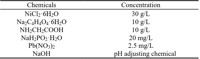
Table 1. Chemical composition of electroless Ni-P plating solution.
Chemicals Concentration
NiCl2·6H2O 30 g/L
Na2C4H4O4·6H2O 10 g/L
NH2CH2COOH 10 g/L
NaH2PO2·H2O 20 mg/L
Pb(NO3)2 2.5 mg/L
NaOH pH adjusting chemical
around 14%. The thickness of the obtained Ni-P coatings was around 10μm. The surface of each Ni-P coating was further polished by mechanical texturing to reduce surface roughness, and thereby to minimize the friction force for media disk operation. The devices and the processes used in this investigation are similar to those used to fabricate a conventional nonmagnetic Ni-P underlayer. The roughness (Ra) of the mechanical texture Ni-P /Al-Mg substrates was 0.5 nm, as determined by atomic force microscopy (AFM). To determine the effect of microstructure on the mechanical strength, corrosion and corrosive wear resistance of electroless Ni-P coatings, specimens were annealed at 230, 240, 250, 260, 280, 290, 350 and 400ºC for 15 min in an electric furnace in a controlled Ar atmosphere. After the electroless Ni-P coating was annealed at various temperatures, the specimens were deposited as a diamond-like carbon (DLC) film with a thickness of 3.0 nm by hot filament chemical vapor deposition (HFCVD). Lee [11] has presented the details of HFCVD, also using an optical analyzer which correlated to transmission electron microscopy (TEM, JEOL JEM-2100F) cross- sectional height to measure the thickness of the DLC film.
2.2 Microstructural observations and mechanical properties of Ni-P coatings and DLC films
The cross-sectional microstructure and elemental contents of the Ni-P coatings and DLC films were studied using scanning electron microscopy (SEM, JEOL JSM-6360) and X-ray energy dispersive spectrometry (EDS, INCA Energy 6587). X-ray diffractometry (XRD) was utilized to examine the crystalline structure of the annealed Ni-P coatings. The surface hardness of the coatings and DLC films was determined using a nanoindentation test system (Criso-UMIS). Cylic loading and unloading with holding times of 10 s at a maximum load of 50 mN were performed to determine the hardness from the penetration depth. The values of electrical conductivity of the Ni-P coatings and DLC films were determined using an Auto Sigama-2000 electrical conductivity meter, and presented as percentages that of the International Annealed Copper Standard (%IACS).
2.3 Electrochemical corrosion and wear testing
The electrochemical corrosion behavior of the annealed Ni-P coatings and DLC films in 3.5 wt.% NaCl solution was studied using potentiodynamic polarization. The potentiodynamic polarization curves were obtained by scanning from 250 mVSCE below OCP to 1000 mVSCE, at a scanning rate of 0.5 mV s-1
. All potentials referred to the saturated calomel electrode (S.C.E.), and platinum wire was the counter electrode. A potentiostat (EG & G Model 273A) and analysis software were utilized. To evaluate the corrosive wear resistance behavior of the specimens, a block-on-ring corrosive wear test carried out in 3.5 wt.% NaCl solution. All of the specimens were cleaned before and after the tests and weighed using an analytical balance (Precisa XS 225A) with a sensitivity of 0.1 mg to determine the corrosive wear loss. Specimens were placed in contact with a rotating ring, which was made of sintered Al2O3 ceramic (99.9% purity, hardness: 1120Hv) with an outer diameter of 22.5 mm and a width of 13.5 mm. The applied load (5 N), sliding speed (1.23 m s-1, or 100 rev min-1
contents of the specimens following wear testing were also studied by using a scanning electron microscopy (SEM, JEOL JSM-6360) equipped with X-ray energy dispersive spectrometry (EDS, INCA Energy 6587).
3. RESULTS AND DISCUSSION
3.1. Characterization of annealed Ni-P coatings and DLC films
The as-deposited Ni-P coating without heat treatment is a metastable phase because phosphorous has limited solubility in nickel. The structure of this metastable deposit is strongly related to the phosphorus content. The previous researcher [12] studied the crystallization process of electroless nickel-phosphorous deposits using X-ray line profile analysis, and indicated the presence of crystalline and amorphous phases coexisting in the as deposited condition. The lattice disorder in the crystalline phase increased with increasing phosphorus content. The deposit with less than 7 wt.% P is a supersaturated solid solution in crystalline nickel [13]. The Ni-P coating with more than 10 wt.% P is completely amorphous [14].
(a) (b)
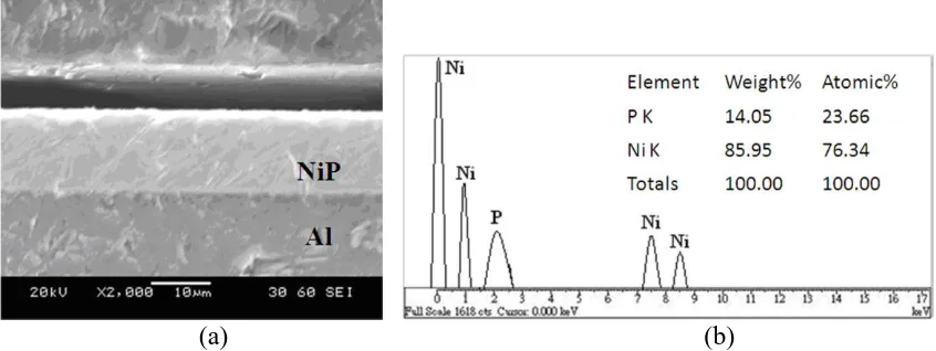
Figure 1. (a) Cross-sectional SEM photomicrograph and (b) EDS elemental analysis of electroless Ni-P coatings annealed at 280°C.
[image:5.596.87.510.383.542.2]
at 280 ºC. The interface between the substrate and the coating is very dense and smooth without any voids. EDS analysis of the electroless Ni-P coatings that were annealed at 230 ºC, 260 ºC and 280 ºC revealed that their P contents (13.82~14.05 wt.%) and Ni contents (86.18~85.95 wt.%) varied very little, and their mean coating thickness was around 10 μm.
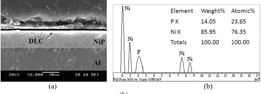
Figure 2 presents the cross-sectional microstructure and the results of the EDS analysis of the electroless Ni-P coatings (10 μm) with DLC films (3 nm) that were annealed at 280ºC. The interface between the duplex layer (Ni-P coating and the DLC film) and the Al-Mg alloy substrate retained a smooth, continuous and compact structure also without any voids or holes. The P (14.03~ 14.05 wt.%) and Ni contents (85.97~86.00 wt.%) in the Ni-P coatings of the duplex layers that were annealed at the four temperatures, 240 ºC, 250 ºC, 260 ºC and 280 ºC, were almost the same.
(a) (b) (b)
Figure 2. (a) Cross-sectional SEM photomicrograph and (b) EDS elemental analysis of electroless Ni-P coatings on which DLC films were deposited, annealed at 280 °C.
Table 2. Electrical conductivity of the annealed electroless Ni-P coating and annealed Ni-P coatings on which were deposited DLC films.
Specimen %IACS
Ni-P 230°C 32.70 ± 0.00
Ni-P 260°C 33.36 ± 0.05
Ni-P 280°C 33.88 ± 0.04
Ni-P+DLC 240°C 33.12 ± 0.04
Ni-P+DLC 250°C 33.16 ± 0.05
Ni-P+DLC 260°C 33.18 ± 0.04
Ni-P+DLC 280°C 33.26 ± 0.05
[image:6.596.86.510.260.414.2] [image:6.596.107.486.519.651.2][image:7.596.135.446.362.568.2]
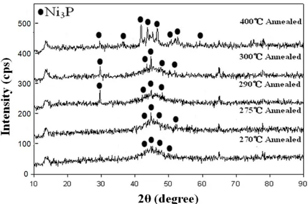
X-ray diffractometry was used to determine the structure of the annealed Ni-P coatings. It indicated that the amorphous as-deposited Ni-P after annealing precipitated out a Ni3P phase whose crystallinity increased with annealing temperature. The increase in the amount of Ni3P precipitate increased the electrical conductivity. This finding can be explained with reference to the results concerning the aging of aluminum alloy in the previous work [16]. The researchers have shown that the growth of precipitates continuously increased electrical conductivity during aging by reducing the number of solute atoms in the aluminum alloy matrix and relaxing the strain fields around those precipitates. Figure 3 presents the X-ray diffraction patterns of the electroless Ni-P coatings that were annealed at temperatures 270~400 ºC. From Fig. 3, more of the clearly crystalline Ni3P precipitate phase is formed as the annealing temperature of the Ni-P coatings is increased. When the annealing temperature reaches 400 ºC, the annealed Ni-P coating comprises mostly the Ni3P phase with a little of the Ni phase. The investigators [17] have also shown a similar result that annealing of pure nickel-phosphorous and nickel-nickel-phosphorous-WC composite coatings at 400 ºC revealed complete crystallization of the matrix to the phases of Ni, Ni2P and Ni3P accompanied by a significant increase of microhardness for all deposits. Further heating at higher temperatures demonstrated a decrease in microhardness of both kinds of deposits.
Figure 3. XRD spectra of annealed electroless Ni-P coatings.
[image:8.596.90.506.160.322.2]
hardening type of behavior, increasing from an initial value of about 450 VHN in the as deposited state to the peak hardness of about 825 to 950 VHN, corresponding to a temperature range of 360 to 400 ºC.
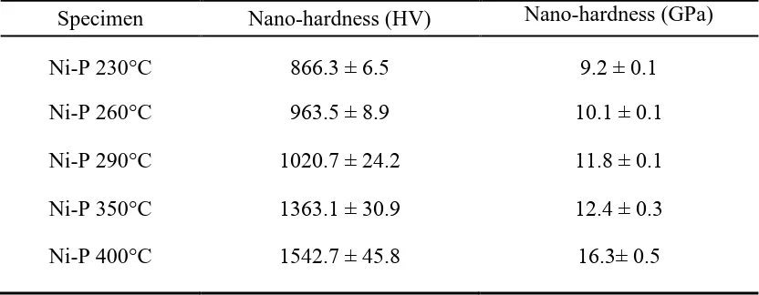
Table 3. Surface nanohardness of electroless Ni-P coatings annealed at 230-400 °C.
Specimen Nano-hardness (HV) Nano-hardness (GPa)
Ni-P 230°C 866.3 ± 6.5 9.2 ± 0.1
Ni-P 260°C 963.5 ± 8.9 10.1 ± 0.1
Ni-P 290°C 1020.7 ± 24.2 11.8 ± 0.1
Ni-P 350°C 1363.1 ± 30.9 12.4 ± 0.3
Ni-P 400°C 1542.7 ± 45.8 16.3± 0.5
Table 4 presents the surface nanohardness of the duplex layer of the annealed Ni-P coatings to which the DLC film was added. The obtained surface nanohardness of the duplex layer also increases with annealing temperature. The DLC film does not obviously increase the surface nanohardness of the Ni-P coating more than does annealing. Following annealing at 280 ºC, the nanohardness of the duplex layer (1027.6 Hv, 11.9 GPa) is almost the same as that of the single Ni-P coating (1020.7 Hv, 11.8 GPa) that is annealed at 290 ºC. This result follows from the fact that the DLC film that was deposited on the annealed Ni-P coatings has quite a high hardness. Since the hard DLC film was deposited on annealed Ni-P coatings that were also quite hard, the DLC film enhances the hardness of the Ni-P coating less than does the annealing.
Table 4. Surface nanohardness of electroless Ni-P coatings on which DLC films were deposited, annealed at 240-280 °C.
Specimen Nano-hardness (HV) Nano-hardness (GPa)
Ni-P+DLC 240°C 903.0 ± 33.0 9.6 ± 0.4
Ni-P+DLC 250°C 912.4 ± 28.7 9.6 ± 0.3
Ni-P+DLC 260°C 936.6 ± 22.1 9.9 ± 0.2
Ni-P+DLC 280°C 1027.6 ± 48.4 10.9± 0.5
3.2. Analysis of electrochemical behavior
[image:8.596.55.535.572.648.2][image:9.596.146.450.128.361.2]
polarization curves. Table 5 presents the corrosion potential (Ecorr), corrosion current density (icorr) and Tafel slopes (ba, bc) that were determined from the polarization curves.
Figure 4. Potentiodynamic polarization curves of annealed electroless Ni-P coatings.
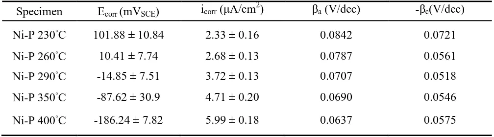
Table 5. Electrochemical characteristics of annealed electroless Ni-P coatings, determined from polarization curves.
Specimen Ecorr (mVSCE) icorr (μA/cm2) βa (V/dec) -βc(V/dec)
Ni-P 230°C 101.88 ± 10.84 2.33 ± 0.16 0.0842 0.0721
Ni-P 260°C 10.41 ± 7.74 2.68 ± 0.13 0.0787 0.0561
Ni-P 290°C -14.85 ± 7.51 3.72 ± 0.13 0.0707 0.0518
Ni-P 350°C -87.62 ± 30.9 4.71 ± 0.20 0.0690 0.0546
Ni-P 400°C -186.24 ± 7.82 5.99 ± 0.18 0.0637 0.0575
[image:9.596.46.550.455.595.2]
degrading the corrosion resistance of the P coatings. Additionally, from Table 5, the electroless Ni-P coating that was annealed at the lowest temperature of 230 ºC had the lowest corrosion current density (icorr) of 2.33 μA/cm2
and the most noble corrosion potential (Ecorr) of 101.88 mVSCE. The Ni-P coating that was annealed at the highest temperature of 400 ºC exhibited the worst electrochemical polarization behavior, and had the highest icorr of 5.99 μA/cm2 and the most cathodic Ecorr of -186.24 mVSCE. Moreover, the higher ba values as compared to bc values indicate that the application of the external current strongly polarizes the anode. This result also shows that the Ni-P coating that was annealed at low temperature below 400 ºC affected the ba values, and decreased the anodic dissolution.
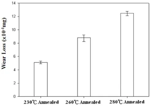
3.3. Wear test
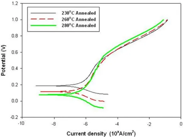
The wear resistance behavior of the coatings was evaluated by performing electrochemical polarization at the same time as a block-on-ring wear performs in a 3.5 wt.% NaCl solution. Figure 5 plots the potentiodynamic polarization curves of the annealed Ni-P coatings that were obtained during the corrosive wear tests. Table 6 presents the corrosion potential (E′corr), corrosion current density (i′corr) and Tafel slopes (ba, bc) that were obtained from these polarization curves. The Ni-P coating that was annealed at 230 ºC had a more noble corrosion potential (183.55 mVSCE) and a lower corrosion current density (2.37 μA/cm2) than Ni-P coatings that were annealed at temperatures above 230 ºC. Moreover, the lower values of two Tafel slopes (ba=0.0546 V/dec, bc=0.0423 V/dec) indicated that the Ni-P coating that annealed at 230 ºC can decelerate the anodic dissolution and hydrogen evolution reaction.
Figure 5. Potentiodynamic polarization curves of annealed electroless Ni-P coatings during wear corrosion tests.
[image:10.596.149.440.444.662.2]
(0.42) and wear loss (0.50 mg) than those of the Ni-P coatings that were annealed at 260 ºC and 280 ºC. The Ni-P coating that was annealed at the lowest temperature of 230 ˚C had the lowest electrical conductivity, the lest Ni3P precipitate and the best electrochemical corrosion resistance; it therefore had the best wear corrosion resistance.
Table 6. Electrochemical characteristics of annealed electroless Ni-P coatings, determined from polarization curves during wear corrosion tests.
Specimen E'corr (mVSCE) i'corr (μA/cm 2
) βa (V/dec) -βc(V/dec)
Ni-P 230°C 183.55 ± 3.44 2.37 ± 0.37 0.0546 0.0423
Ni-P 260°C 103.79 ± 5.04
3.35 ± 0.15 0.0721 0.0514
Ni-P 280°C 79.59 ± 8.19 3.68 ± 0.10 0.0784 0.0684
[image:11.596.46.550.208.306.2]Figure 6. Friction coefficient (μ) vs. time for annealed electroless Ni-P coatings during wear corrosion tests.
[image:11.596.196.400.340.495.2] [image:11.596.177.421.551.723.2]
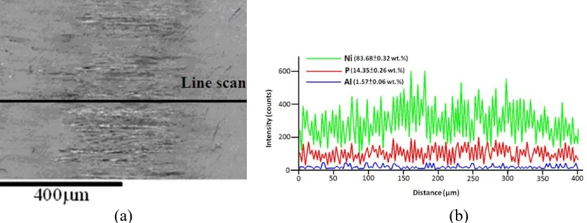
The Ni-P coating that was annealed at a higher temperaure of 280 ˚C had the worse wear corrosion resistance; the highest friction coefficient (0.92) and wear loss (1.25 mg); the highest active corrosion potential (79.59 mVSCE) and the highest corrosion current density (3.68 µA/cm2), because it has the highest electrical conductivity and the most Ni3P precipitate. After the annealed Ni-P coatings had undergone wear corrosion testing, EDS line scanning analysis of the wear corrosion scars was performed. The Ni-P coatings that were annealed at the lower temperatures of 230 ˚C and 260 ˚C still included Ni and P elements, indicating that the Ni-P coatings that were annealed at these two temperatures resisted wear corrosion in 3.5 wt.% NaCl solution.
However, the surface of the Ni-P coating that was annealed at the high temperature of 280 ˚C revealed elemental Al (1.57 wt.%) from the aluminum alloy substrate after corrosive wear testing, as shown in Fig. 8. This result is evidence of the poor wear corrosion resistance of Ni-P coating that is annealed at 280 ˚C. All of these results agree strongly with the previous results concerning electrical conductivity, the amount of Ni3P precipitates and potentiodynamic polarization. Therefore, we suggest that annealing electroless Ni-P coatings annealed at a temperature of over 260 ˚C reduces their wear corrosion resistance by increasing their electrical conductivity and the amount of Ni3P that precipitates out.
(a) (b)
Figure 8. (a) Wear scar and (b) EDS elemental analysis of annealed electroless Ni-P coatings following wear corrosion tests.
[image:12.596.89.510.371.531.2]
Figure 9. Potentiodynamic polarization curves of annealed electroless N-P coatings on which were deposited DLC films during wear corrosion tests.
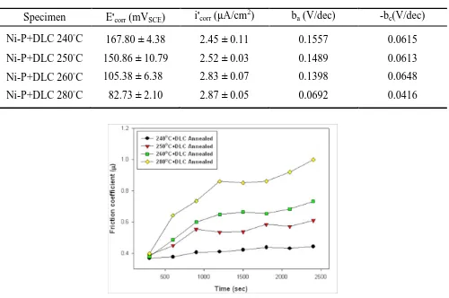
Table 7. Electrochemical characteristics of annealed electroless Ni-P coatings on which were deposited DLC films, determined from polarization curves during wear corrosion tests.
Specimen E'corr (mVSCE) i'corr (μA/cm2) ba (V/dec) -bc(V/dec)
Ni-P+DLC 240°C 167.80 ± 4.38 2.45 ± 0.11 0.1557 0.0615
Ni-P+DLC 250°C 150.86 ± 10.79 2.52 ± 0.03 0.1489 0.0613
Ni-P+DLC 260°C 105.38 ± 6.38 2.83 ± 0.07 0.1398 0.0648
Ni-P+DLC 280°C 82.73 ± 2.10 2.87 ± 0.05 0.0692 0.0416
[image:13.596.148.450.67.296.2] [image:13.596.50.550.397.729.2]
Figure 11. Wear loss of annealed electroless Ni-P coatings on which were deposited DLC films following wear corrosion tests.
When the DLC film that was deposited on the Ni-P coating was annealed at a temperature of over 240 ºC, the worse wear corrosion resistance characteristics were worsened. Annealing at the high temperature of 280 ºC yielded a significantly active corrosion potential (82.73mVSEC), a high corrosion current density (2.87 μA/cm2), and a significantly high friction coefficient (0.87) and wear loss (1.13 mg). The wear scars of the duplex layers following the wear corrosion tests were observed by EDS line scanning analysis, with the DLC film deposited on Ni-P coatings that were annealed at 240 ºC, 250 ºC and 260 ºC. The corrosive wear surfaces of these duplex layers still revealed the presence of Ni, P and C elements, clearly indicating that the DLC film helped to protect the electroless Ni-P coating from corrosive wear failure in 3.5 wt.% NaCl solution. However, when a DLC film was deposited on the Ni-P coating that was annealed at the high temperature of 280 ºC, its corrosive wear surface exhibited elemental Al (1.35 wt.%) from the aluminum alloy substrate, indicating the poor wear corrosion protection provided by the DLC film on this annealed Ni-P coating (Fig. 12).
(a) (b)
[image:14.596.159.444.85.286.2] [image:14.596.82.508.589.731.2]
These results indicate that depositing the hard DLC film on a Ni-P coating that has been annealed at a higher temperature and therefore has a higher surface hardness weakens the adhesion of the DLC film on the Ni-P coating, reducing the wear corrosion protection that it provides to that coating.
4. CONCLUSIONS
(1) Annealing increased the hardness of electroless Ni-P coatings to an extent that increased with annealing temperature by causing the precipitation of Ni3P.
(2) Annealing electroless Ni-P coatings on which were deposited a DLC film increased their hardness to an extent that increased with annealing temperature, but the DLC film did not increase hardness when the annealing temperature was 280˚C. Up to this temperature, annealing was more effective than depositing an ultra-thin DLC film in strengthening the electroless Ni-P coatings.
(3) According the results of potentiodynamic polarization testing in 3.5wt.% NaCl solution, the corrosion resistance of electroless Ni-P coatings fell as the annealing temperature increased, the coating that was annealed at 230˚C had the highest corrosion resistance, while that annealed at 400˚C had the lowest corrosion resistance.
(4) Depositing an ultra- thin DLC film on electroless Ni-P coatings that had been annealed at low temperature improved their wear corrosion resistance. However, the Ni-P coatings that was annealed at high temperature of 280˚C and was covered by a DLC ultra-thin film contained elemental Al after wear corrosion testing, as revealed by EDS line scanning analysis. The wear corrosion failure was attributed to the fact that increasing the annealing temperature increased the hardness of the Ni-P coating while weakening the adhesion of the hard DLC film on it.
ACKNOWLEDGEMENTS
The authors would like to thank the Ministry of Science and Technology of the Republic of China, Taiwan, for financially supporting this research under Contract No. MOST 104- 2221-E - 231- 001 - and MOST 104- 2745-E - 231- 001 –
References
1. N. Dwivedi, R. J. Yeo, P. S. Goohpattader, N. Satyanarayana, S. Tripathy, C. S. Bhatia, Diam. Relat. Mater. 51 (2015) 14
2. W. W. Scott, B. Bhushan, Wear 243 (2000) 31
3. P. Papakonstantinou, J. F. Zhao, A. Richardot, E. T. McAdams, E. T. McLaughlin, Diam. Relat. Mater. 11 (2002) 1124
4. C. K. Lee, Diam. Relat. Mater. 17 (2008) 306
5. W. Zhang, A. Tanaka, B. S. Xu, Y. Koga, Diam. Relat. Mater. 14 (2005) 1361
6. B. R. Acharya, J. N. Zhou, M. Zheng, G. Choe, E. N. Abarra, K. E. Johnson, IEEE Trans. Magn. 40 (2004) 2383
8. S. N. Piramanayagam, H. B. Zhao, M. Dewi, B. C. Lim, J. Magn. Mater. 287 (2005) 271
9. K. H. Krishnan, S. John, K. N. Srinivasan, J. Praveen, M. Ganesan, P. M. Kavimani, Metall. Mater. Trans. A 37 (2006) 1917
10.C. León, E. García-Ochoa, J. García-Guerra, J. González-Sánchez, Surf. Coat. Technol. 205 (2010) 2425
11.C. K. Lee, Appl. Surf. Sci. 254 (2008) 4111
12.J, Sudagar, G. Bi, Z. Jiang, J. Lian, Int. J. Electrochem. Sci. 6 (2011) 2767
13.R. Muraliraja, D. Sendilkumar, D. R. Elansezhian, Int. J. Electrochem. Sci. 10 (2015) 5536 14.X. Q. Xu, J. Miao, Z. Q. Bai, Y. R. Feng, Q. R. Mia, W. Z. Zhao, App. Surf. Sci. 258 (2012) 8802 15.B. H. Liu, F. Y. Liao, J. H. Chen, Thin Solid Films 537 (2013) 263
16.J. T. Jiang, W. Q. Xiao, L. Yang, W. Z. Shao, S. J. Yuan, L. Zhen, Mater. Sic. Eng. A 605 (2014) 167
17.C. Zhao, Y. Yao, J. Mater. Eng. Perform. 23 (2014) 193