Geometric considerations for the design of
production-friendly high-speed ship hull forms
S W Boyd1*, A H Day2,andI E Winkle2
1Fluid Structure Interactions Research Group, School of Engineering Science, University of Southampton, Southampton, UK
2Department of Naval Architecture and Marine Engineering, Universities of Glasgow and Strathclyde, Glasgow, UK
The manuscript was received on 23 July 2004 and was accepted after revision for publication on 7 June 2005.
DOI: 10.1243/147509005X10486
Abstract: This study examines the feasibility of designing high-speed ships with hull-form geometry suitable for planked construction, with the aim of reducing the hull construction cost. An algorithm is developed for placing prismatic planks on to a three-dimensional hull form to represent a planked construction. A number of well-known hull forms are examined using the algorithm developed in order to assess their suitability for this construction technique. It is shown that typical round-bilged forms are unsuitable for planked construction, since an undesirably large proportion of the material strength will be used in forming the structure. A conceptual design for a simplified hull form is developed which contains significantly reduced levels of double curvature, and this design is shown to be suitable for planked construction, as well as offering the potential for advantages in conventional plated construction. It is further shown that the hydrodynamic resistance of this conceptual design is comparable with a more traditional form.
Keywords: geometry, design, high-speed ships, hull forms, construction cost
1 INTRODUCTION economic construction. Similar concepts have been
developed utilizing fibre-reinforced polymers (FRPs) in the form of pultruded planks. However, the appli-There is an increasing demand for cost-effective
construction of marine vehicles in order to stay cation of FRP planks has been limited to mainly civil applications [2,3].
competitive in a now world market. Studies have
shown that the proportion of ship construction cost At present, the use of preformed components (in particular, aluminium extrusions) has been con-attributed to direct labour can be as much as 45 per
cent for fast private super-yachts, 33 per cent for centrated in areas of the ship in which the geometry largely consists of planar or near-planar surfaces, commercial fast ferries, and 28 per cent for fast patrol
vessels [1]. One method of reducing labour input is such as decks, bulkheads, and superstructure panels. However, there are potentially large gains to be to standardize the component parts that make up
the ship structure. In recent years, there has been made in constructing geometrically more complex structures, such as the hull shell plating, using pre-a move towpre-ards the use of extruded pre-aluminium
components in substantial parts of high-speed ship formed planks. This is especially true of FRP con-struction where a plank-based system could reduce, structures. There are now a variety of standard
and proprietary extruded planks, which incorporate or even eliminate, the need for a female mould. Traditional ship planking techniques using wood stiffeners and edge details to allow rapid and
planks employed ‘stealers’ and tapered planks to help to achieve the required geometry, especially near the * Corresponding author: Fluid Structure Interactions Research
ends of the hull where the girth can reduce rapidly. Group, School of Engineering Science, University of Southampton,
However, the nature of the manufacturing methods Highfield, Southampton SO17 1BJ, UK. email: sbody@
limits the plank geometry to purely prismatic sections. in a right-handed global coordinate system. If this is not the case for a particular software package, appro-While the sections could clearly be cut and tapered,
priate transformations must be applied to the data. much of the advantage of prefabrication would
It is advantageous computationally if the data be lost, especially as tapering the planks would
representing the surface are output in the form of a generally mean the loss of the edge detail, and
con-topologically rectangular grid (i.e. that there are the sequent difficulty in joining the planks along seams.
same number of xdata points at eachycoordinate Therefore, it is likely that the hull geometry would
and vice versa). If the data are not output in this have to be modified in order to allow the hull to
form, a number of methods can be implemented to be constructed using only prismatic planks without
create the topologically rectangular grid including unacceptably high levels of curvature and associated
spline fitting or a manual method. forming stresses.
Within this study an algorithm has been developed
2.2 Planking methodology to position planks of a specified constant width on
any given three-dimensional surface. From knowledge Figure 1 shows a plank located on a three-of the position three-of each plank on the surface, the
dimensional body and this general case is used to curvatures induced on the planks by the surface demonstrate the method used within the algorithm. can be calculated and used to determine the stress The upper edge of the plank follows the direction of induced by forming. There are a number of inputs the longitudinal lines and intersects the transverse to the procedure that can have a significant effect on lines. The procedure finds the position of the lower the magnitude of the forming stress including the plank edge on each of the transverse lines.
direction of the planking and/or the start position of In order to simplify the problem of calculating the
the chosen planking strategy. position of the next plank edge, a local coordinate
This paper describes the development of the system (j,g,f) is constructed at the intersection planking algorithm and the subsequent calculation of point I
j. It consists of a vectorVL, defining the edge curvature and forming stress. The algorithm is applied of and being tangential to the plank at the inter-to a number of hull forms inter-to investigate their possible section point I
j, and defines the j axis of the local construction using a planked technique. Design con- coordinate system. The vector V
t is in the plane of siderations are identified and implemented through the plank, running transversely orthogonal to its edge the conceptual design of a simplified hull form. This (V
L) and defines the g axis of the local coordinate was shown to have similar hydrodynamic resistance system. Finally,V
nis normal to the plank surface and to a conventional design of comparable dimensions, is orthogonal to bothV
LandVtand defines thefaxis while offering substantial advantages in terms of of the local coordinate system.
ease of planked construction. The vector V
L is constructed at the intersection point Ij(Fig. 2) using points defining the upper plank edge or those of the data point net. Various methods
2 DESCRIPTION OF THE PLANKING ALGORITHM
2.1 Surface data
There are a number of software packages available for the production of ship lines, which include tools for the fairing and smoothing of the hull shape, and calculation of immersed volumes, areas, and initial stability.
It is reasonable to assume that most hull forms are designed using computer aided design (CAD) software. This software generally allows the user to output a file containing a numerical representation of the surface of the hull. It is important that the algorithm developed here can be used independently of any particular surface definition software. Here it
[image:2.595.306.547.538.719.2]lies on the present girthwise segment and where it lies on any of the subsequent girthwise segments. The methods used to deal with these two scenarios have been described in detail in reference[4].
The entire procedure is repeated for each girthwise section until all the sections have been filled with planks. The surface of the body has now been planked and the curvature analysis can begin. However, there are a number of points that must be considered prior to beginning the planking procedure; these include planking direction and the starting line of data.
2.3 Choice of planking direction and starting line
The choice of planking direction will have a signi-ficant influence on the stress induced on the plank Fig. 2 Local coordinate system located at the
inter-section point I
j due to forming. In the positioning of planks on
to a surface, the force required to ensure a close fit between adjacent planks and the stresses that of constructing the vectorV
Lcan be used including the curvature of the plank causes are important linear interpolation or spline fitting. The advantages
parameters. and disadvantages of each and their influence on the
The easiest and most commonly found method of final outcome of the algorithm will be discussed and
planking a hull form is longitudinally. The technique demonstrated later.
involves laying planks longitudinally on to a network From Fig. 2 the next plank edge will lie on the line
of frames. Each plank is forced to lie against its neigh-of the net points running girthwise from point I
j. A bour to create a watertight outer skin. Planking a vectorVccan be constructed using the net points Ni
vessel transversely could also be considered and may and Ni+1.V
cdefines the (as yet unknown) direction have certain advantages. However, it also has some along the rectangular net to the next plank edge. It
major disadvantages. A number of hull forms were is assumed that both VL and Vc are in the plane
examined to assess a transverse planking strategy. It of the plank. Using this assumption, the vector Vn
was found that the relatively tight bilge radius, often normal to both V
Land Vc can be constructed. The found on high-speed vessels, prevented a successful final vector Vt, normal to both VL and Vn can be
transverse planking strategy. The stress caused by the constructed. Using the known vectors VL and Vc,
orthogonal bending of the plank far exceeded the calculated from the net point data, the remaining
allowable stress of the plank used in the investi-vectors are calculated using the relationships
gation. Diagonal planking is also used in the con-V
n=Vc×VL (1) struction of wooden yachts and boats. However, this
method involves tapering each plank to fit seamlessly V
t=VL×Vn (2) against its neighbour. As prismatic planks are being
dealt with, tapering of the planks is not considered As discussed, V
L and Vc are coplanar in the plane
of the plank. To find the distance to the next plank an option, as it would be both expensive and labour intensive. In the present study, only planking from edge (the projected plank width) in the direction of
V
c, the angle betweenVcandVtmust be found. It is keel to sheer and from sheer to keel are examined. Depending on the planking strategy being adopted, also important to identify the position of V
t with
relation to Vc as it will influence the sign of the j the planking procedure requires an appropriate starting line of data points which will define the coordinate. With the origin of the local coordinate
system (j,g,f) located at the intersection point I
j, first plank edge. Based on the longitudinal planking directions mentioned above, the starting lines of data the position of the next plank edge can be defined
by the relationship could be located at the hull discontinuities such as
the keel line, sheer line, or chine line. As an example,
(j,g,f)=(±w, 0,wtanh) (3)
a sketch of a hull form is shown in Fig. 3 and can be used to demonstrate the effect of choosing the start-where w is the manufactured plank width and h is
the angle betweenV
[image:3.595.43.285.65.247.2]Fig. 3 Effect of different planking strategies
lies along the keel line and up the stem line. It is 4. What effect will modifications designed to improve suitability for planked construction have on hull clear to see that any planks placed along this line
will run along the keel and sweep up the stem and performance? off the hull through the sheer line. If, however, the
In addressing the first three questions the plank starting point were located on the keel line alone,
curvatures must be known. It is important at this then the plank would sweep off through the stem
stage to ensure that the correct curvatures are being line (Fig. 3(b)). The former option would produce a
analysed and truly represent the curvatures that are plank position with high curvature and therefore
developed within the plank. high stress, whereas the latter option would produce
less curvature or induced stress.
2.5 Curvature 2.4 Output from planking algorithm
One fundamental concern in the design of a hull The output from the planking algorithm consists of form is the determination of fairness or smoothness the plank positions on the three-dimensional body. of the surface. In general, one of the most commonly The positions can then be used to determine the used metrics in ship design software is Gaussian effect of the choice of planking direction or the effect curvature. Gaussian curvature is the product of the of the hull characteristics. This is carried out by minimum and maximum principal curvatures located calculating the curvature of the planks combined at each and every point on a surface. However, in with knowledge of the plank geometry to produce a the context of the current study, the curvatures of
stress induced by forming. interest are those in the plane of and orthogonal to
With respect to hull-form geometry a number of the plank surface and are therefore related to the
questions can be addressed. plank rather than the underlying surface. These
cannot be easily obtained from knowledge of the 1. What is the maximum curvature (minimum radius
magnitude of the Gaussian curvature. of curvature) that each plank exhibits as it lies on
At any point on a three-dimensional curve a the surface?
moving trihedroncan be constructed. This consists 2. What percentage of the hull can be planked if the
of three orthogonal vectors and three orthogonal curvature is not allowed to exceed a certain value?
planes. The orthogonal vectors are those constructed 3. How can the design be modified to reduce the
as the local coordinate system in section 2.2. Each curvature of the planks?
of the three planes contains the point on the curve and one of the vectors. The planes are known as the The last question leads to another important factor
with respect to high-speed hull forms. osculating plane(containingV
[image:4.595.165.432.70.279.2](containing Vc), and the normal plane (containing 2.6 Derivative calculation V
n). Figure 4 shows the construction of a moving In the calculation of the derivatives for the local trihedron at a point P.
coordinate system in section 2.2, two techniques The normal vector in Fig. 4 points in the direction
were described: a numerical method and a spline- or that the curve is turning and towards the centre of
curve-fitting method. Initially the numerical method curvature. The magnitude of the normal vector will
was used. Here central differencing was employed as provide the magnitude of the radius of curvature at
it is relatively simple and extremely robust. However, the point P. In a global coordinate system this normal
when a similar method was used for the curvature vector will provide the principle curvature. In this
derivatives in section 3.1, the results became very case, interest lies in the curvature in the planes of
erratic. This phenomenon only occurred when large the plank and so the normal vector is found in the
numbers of points were used to define the curve. local coordinate system. The principal normal vector
This was surprising as it was felt that a piecewise found using any coordinate system could be divided
linear method would become more accurate with into its coordinate components. An equation for each
increasing curve definition. component in the principal curvature allows the
The problem was demonstrated by planking a curvature orthogonal to and in the plane of the plank
cylinder around its circumference; the cylinder had a to be found.
radius of curvature of 6 m (equivalent to a curvature The radiusRof curvature for any point on a space
value of 1.667×10⁻¹m−1). In this case, the radius curve can be given by
of the cylinder predicts the orthogonal curvature of the plank. Using the linear interpolation method 1
R=
|Pu×Puu|
|Pu|3 (4) with nine points defining the cylinder the curvature
was found to be relatively smooth and moderately The superscript u represents differentiation with accurate. 21 points increased the accuracy of the respect to the parametric variableu. calculation. However, when 151 points were used, By dividing up the principal normal vector into its then the curvature developed an oscillation about local coordinate component parts the expressions for the actual radius of the cylinder. The comparison orthogonal and in-plane curvatures respectively are between 9, 21, and 151 defining points is shown in
obtained as Fig. 5.
The problem arises in the definition of the local 1
R(g)=
d2g/dj2
[1+(dg/dj)2]3/2 (5) coordinate system. Although the raw data can be assumed to be extremely accurate for the cylinder, the transformation of the data into the local coordi-1
R(f)=
d2f/dj2
[1+(df/dj)2]3/2 (6) nate system induces an error in the data. This is
The calculation of the derivatives can be under-taken either numerically or by using a curve- or spline-fitting routine.
[image:5.595.61.546.518.738.2]because linear interpolation is used to calculate the The planking algorithm was applied to three hull forms, namely NPL Parent [5], NPL 6a [7], and Series local coordinate system. This results in flat and even
concave points on the cylinder surface. Therefore, the 64 5s [10], all scaled to 50 m overall length. These are shown in Fig. 6. Each hull was planked using a plank curvature solutions for curves with high definition
must be addressed. However, it is common in naval width of 0.6 m. The plank width was based on the architecture to define hulls with 21 or 41 stations
and waterlines. If this convention is followed then induced numerical error can be kept to a minimum. The use of a spline or curve to represent the plank is one solution to eliminate the numerical inaccuracies of using linear interpolation to calculate curvature. However, a certain amount of control of the surface shape may be lost. If it is assumed that the underlying data are accurate, an inappropriate spline-fitting procedure may distort the surface and lead to unrepresentative curvatures. A cubic spline was used to represent the cylinder surface and a least-squares method was used to assess the level of fit of the cubic spline. The resulting derivatives are then calculated and the results showed an increase in accuracy compared with the 151-point linear inter-polation method previously described. This method is much more time consuming to implement in the context of a practical ship form, and the large number of spline combinations that are assessed for best fit could make automatic implementation difficult. For this reason it was decided to produce results using the linear interpolation method with a suitable density of points to produce reliable results without curvature oscillations.
3 APPLICATION OF PLANKING TOOL TO EXISTING HULL FORMS
A number of well-documented existing hull forms have been modelled and subsequently planked using an implementation of the planking algorithm described in the previous section. By examining well-known hull forms representative of modern high-speed vessels the hull parameters that influence the success of a planked construction technique can be identified. Based on the results obtained from this study conceptual designs for high-speed craft suit-able for planked construction can be developed. In all cases the hulls are planked either from keel to sheer or from sheer to keel.
The hull forms examined are from the NPL round-bilge displacement series [5], the extended NPL series [6–8], and the Series 64 methodical series [9]. It can be said that the largest length-to-breadth ratio hulls in the extended NPL series [7] are reason-ably representative of present high-speed catamaran
[image:6.595.305.546.158.726.2]geometry of a commercially available pultruded limited to 10 per cent of the ultimate tensile strength; glass-reinforced plastic plank. The properties of the for the ACCS plank discussed here, the maximum plank were used to assess the stress induced on working stress is assumed to be 48.5 MPa.
the plank through forming. The plank is known as Of course the proportion of strength available the advanced composite construction system (ACCS) for forming must only be a small proportion of and is shown in Fig. 7. Details of the plank’s geometry the allowable working stress. In the context of this and material properties are presented in Table 1. example the allowable forming stress is limited to In the current study, the relationship between 10 per cent of the allowable working stress (equivalent curvature and stress is approximated in accordance to 1 per cent of the ultimate tensile strength of the
with linear bending theory by panel) and is assumed to be 4.85 MPa. If the plank
is subjected to orthogonal curvature only, then, K
max= 1 R
min
= smax E
xymax
(7) based on the plank dimensions given in Table 1, the maximum allowable curvature is 8.362×10⁻³m−1. A similar calculation for a plank subjected to in-plane whereKis the curvature,Ris the radius of curvature,
curvature only gives a maximum allowable curvature yis the distance from the neutral axis,E
xis the
longi-of 1.115×10⁻³m−1. In practice, for many hull forms, tudinal Young’s modulus of the plank, ands
maxis the
maximum allowable forming stress. the plank will be curved in both directions simul-When deciding on the allowable forming stress, taneously; however, an initial indication of the feasi-careful consideration must be given to the material bility of using a planking technique may be obtained behaviour. Some FRP composite materials, such as by considering these curvatures independently. those consisting of glass and polyester, are prone to The results presented in Fig. 8 show the in-plane microcracking at strains well below the failure strain. and orthogonal curvatures and the rate of change in The value of the strain at which this microcracking twist angle for the first plank on the three test hulls occurs depends on the exact nature of the material; planked from keel to sheer. Figure 9 shows the curva-in the current study a relatively conservative assump- tures and twist results for the first plank when the tion is made that the maximum working stress is hull forms are planked from sheer to keel. The results indicate that the orthogonal curvature induced on the planks is within the maximum allowable value. However, the in-plane curvature even for the first plank exceeds the limiting value, indicating that the forming stress resulting from in-plane curvature is an undesirably high proportion of the working strength of the plank. This forming stress must be reduced if planking methods are to be successful.
The development of in-plane curvature is not a direct consequence of any individual hull parameter. It can reasonably be assumed that, when planking from keel to sheer, some in-plane curvature may be developed owing to the curvature of the keel line; likewise, when planking from sheer to keel, the sheer line may not be straight. However, in both cases, the curvature of the starting line does not account for the large amounts of in-plane curvature found in the results.
Fig. 7 ACCS pultruded GRP plank
[image:7.595.45.286.428.606.2]It can be shown that in-plane curvature is developed by the combination of plank twist and orthogonal curvature. For a single plank, it is possible Table 1 ACCS plank geometric and material properties
to choose a path over a non-prismatic hull surface
Description Symbol Value Units which minimizes the energy related to forming
stresses in some average sense. If the plank is
Young’s modulus E
x 14.5 GPa wide compared with its thickness, then the bending
Breadth of plank B 600 mm
Depth of plank D 80 mm stiffness in plane will be greater than the
bend-Longitudinal tensile strength s
[image:7.595.45.284.675.737.2](a) Orthogonal curvature
(b) In-plane curvature
(c) Twist
Fig. 9 Curvature and twist for first planks on hull (a) Orthogonal curvature
(b) In-plane curvature
(c) Twist
forms planked from sheer to keel Fig. 8 Curvature and twist of first planks on hull forms
[image:8.595.48.548.55.711.2]expected that the plank would follow a path that pre- 4 CONCEPTUAL DESIGN OF A SIMPLIFIED HULL FORM SUITABLE FOR PLANKED dominantly minimizes in-plane curvature. However,
if the same approach is applied to choose the path CONSTRUCTION of a second plank, the two planks will not generally
lie adjacent to each other everywhere, resulting The study of existing hull forms indicates that a reduction in double curvature is a key goal in in a discontinuous surface, and therefore a
non-watertight hull form. In order to generate a practical increasing the ease with which ship hulls may be constructed using prismatic planks without incurring hull form, the second plank must be constrained
to follow the edge of the first plank, leading to excessive forming stresses. A concept design study was then carried out in order to investigate the additional stresses.
In traditional boatbuilding these stresses are feasibility of reducing doubly curved plating without increasing hydrodynamic resistance.
reduced by ‘splining’ the second plank to fit the
curvature of the first. However, if the construction The concept design study falls under the heading of design for production, which in a marine sense is is confined to prismatic planks, the orthogonal
curvature and the twist of the hull surface, combined the design for minimum cost of ship production through ease of construction. However, this subject with the requirement for a continuous watertight
surface, force the development of additional in-plane is far reaching and encompasses the design not only of the hull form but also of the systems required for curvature.
The curvatures and twist of the first plank of the ship operation and stretches from concept design to final out-fitting. Lamb [11] comprehensively dis-NPL parent form, planked from keel to sheer (Fig. 8),
can be used to demonstrate the development of cussed the concepts behind design for production. However, the concept design study in the present in-plane curvature due to twist and orthogonal
curvature. research deals only with the outer shell structure of
the hull form. Lamb [11] discussed the design for The high in-plane curvature located at
approxi-mately 32 m (Fig. 8(b)) is due to the combination of production problems associated with the hull form shape and highlighted the fact that simplified forms twist and orthogonal curvature as the plank crosses
the bilge radius. The hull geometry in the region are not new and there have been a number of studies that have investigated hull forms with straight frames of the first plank changes from being a relatively
horizontal flat-bottomed section near the stern to a from as early as 1917. In all these studies the over-lying important factor is the minimization of shell nearly vertical section near the bow, producing the
twist. As the hull becomes narrower towards the bow, plating that contains double curvature. The reason is that creating doubly curved panels requires signi-orthogonal curvature is introduced, the combination
resulting in in-plane curvature. Conversely, the plank ficantly more effort than those with only single curvature, commonly referred to as developable located at the sheer line (Fig. 9) has less twist and a
slightly greater orthogonal curvature, but overall less surfaces, which can be defined as those which have one or both of the two principal curvatures equal in-plane curvature.
Based on the results obtained from the study of to zero.
The above discussion on design for production for well-known high-speed hull forms, the amount of
double curvature of these hulls results in the com- hull-form design deals exclusively with traditional plate welding construction techniques. In the case bination of twist and orthogonal curvature, which
ultimately leads to undesirable in-plane curvature in where the hull will be manufactured from preformed pultruded profiles it is already known that the planks a hull constructed with prismatic planks. In order
to take advantage of the possible reduction in hull will be developable. The aim of the present work is to redesign the hull form to reduce the double construction cost of a vessel by using a planked
con-struction technique, the hull form must be designed curvature present in the hull-form shape to ease construction with an alternative technique. The with the intention of reducing double curvature as
far as possible. However, since fuel costs form a resulting hull form is examined hydrodynamically and compared against a suitable ‘parent’ form. major proportion of the operating costs of
high-speed vessels, the potential reduction in construction A round-bilged catamaran demihull form was chosen as the ‘parent’ form as it could be considered cost must not be offset by increased fuel costs due
to higher-power requirements, or by reduced speed. broadly typical of modern design practice. The NPL 6A derivative developed by Molland et al. [7] was Thus the reduction in the doubly curved area must
A conceptual design for a highly simplified demi-hull form suitable for planked construction was then developed for the purposes of comparison. The hull was based on one of the forms studied by Warren and Kecsmar [12]. The form studied by Warren and Kecsmar had rectangular sections throughout its length (apart from a small bilge radius), while the beam was constant over 60 per cent of its length from the stern with a straight taper to the bow. This form is naturally singly curved above the bilge and there-fore ideally suited to form the basis of an investi-gation into hull forms designed specifically for planked construction techniques, avoiding problems associated with double curvature.
In order to draw meaningful comparison between
the parent and the simplified hull forms, a number Fig. 10 Simplified hull form developed for com-parative study
of design parameters must remain constant between the two designs. In the current study, the length was
kept constant in order to keep the Froude number orthogonal curvature is located at the transition between parallel body and the taper to the bow. constant at the design speed, while the displacement
was kept constant in order to ensure that vessels had Figure 11a shows the comparison between the ortho-gonal curvature in the third plank of the two designs. comparable functionality. Once these were fixed, the
beam and draught must be chosen to maintain the The figure shows that the maximal value of the ortho-gonal curvature of the simplified form is slightly displacement at the correct value. If the objective
were simply to minimize the resistance, then an larger than that of the parent form and marginally exceeds the proposed maximal value based on the optimal beam-to-draught ratio could be found;
how-ever, in practice the beam of the demihulls of high- considerations of the forming stress indicated in section 3. In practice, it is highly likely that subtle speed catamarans is often constrained by the need
to accommodate appropriate machinery and pro- modifications to this region would reduce the ortho-gonal curvature produced to a value within the limit pulsion. It was thus decided for the concept study
to maintain the beam, in order to allow accom- proposed.
The main advantage of the simplified form results modation of similar sized engines and propulsion
machinery. The immersed transom area was also from the reduced in-plane curvature and twist com-pared with the parent form. Examples are shown kept constant, as it is believed to be an important
parameter in the resistance of vessels with transom for the third plank on each of the two designs in Figs 11(b) and (c). As expected, the highly simplified sterns.
Adopting these constraints, and using the Warren– form demonstrates zero in-plane curvature and twist, thus satisfying the proposed constraint on Kecsmar form as a starting point, a conceptual
design for the highly simplified catamaran demihull forming stress; the NPL 6A form displays substantial curvature and twist near the bow and violates the form was developed which could be compared
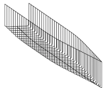
directly with the NPL 6A design. A wire frame model limit on forming stress.
Having demonstrated the improved suitability for of the design is shown in Fig. 10. One key feature of
the design from the point of view of construction is planked construction of the simplified form com-pared with the parent hull, a series of model tests the definition of a well-defined region above the bilge
radius within which a planked construction might were carried out in order to compare the calm-water resistance of the two catamaran forms, The first be used.
This demihull form was planked using the plank- adopted the NPL 6A form as demihulls, while the second used the simplified form. These have been ing algorithm. The results showed that there is no
in-plane curvature and no twist in any of the planks described in detail in reference [13]. Figure 12 shows the resistance ‘penalty’ plotted against Froude located above the bilge radius. The side shell above
the bilge radius is the most obvious place to apply number for the highly simplified form, expressed as a percentage of the resistance of the parent form. a planked construction technique as it has been
[image:10.595.317.533.64.247.2]Fig. 12 Resistance penalty for a simplified hull (com-pared with the parent hull)
5 DISCUSSION
Many issues remain to be resolved before the con-struction of ships using pultruded FRP planks could be considered in practice. In particular, the trans-verse strength of the material is a potentially difficult issue. Joining the planks along edges (seams) may not be a major problem, as existing systems have proved quite successful; however, butt joints may be more problematic. This is of particular concern in the construction of ships long enough that modular construction is desirable, and where limitations related to road transport restrict the lengths of planks which might be delivered. In addition, since it is clear from the current study that some regions of the ship would have to be constructed using more conven-tional techniques, a system for joining pultruded planks on to conventional mouldings and, indeed, other materials would be required.
Nonetheless the study has shown that it is potentially feasible to design a high-speed catamaran demihull so that a substantial proportion may be constructed using an FRP planking system with-out significantly compromising hydrodynamic resist-ance. While the focus of the current study was placed on the construction of planked ships, it should be noted that there might also be substantial benefits to be gained in reducing the geometric complexity using traditional plating construction techniques. (a) Orthogonal curvature
(b) In-plane curvature
[image:11.595.304.549.70.212.2](c) Twist
Fig. 11 Curvature and twist of the third plank on
6 CONCLUSIONS a simplified hull form compared with the
parent form
The planking algorithm has been shown to provide a useful tool for the evaluation of present-day and resistance penalty for the simplified form is between
0 and 3 per cent; however, it must be remembered future hull form designs for construction using a planked technique. It has been shown that present-that the simplified hull was developed without any
for Structural Applications in Construction, 2002, construction using planking technologies owing to
pp. 445–455 (Thomas Telford, Southampton). high proportions of the surface containing double
3 Mottram, T. Why is the design of primary con-curvature.
nections a major engineering issue? 6th CoSACNet Simplified forms provide an ideal opportunity to Workshop, Warwick, UK, 2002.
exploit the advantages of planked construction tech- 4 Boyd, S. W. The use of pre-formed composites nologies by dramatically increasing the ratio of single for fast marine craft construction. MSc thesis, to double curvature, without significantly affecting University of Glasgow, Glasgow, 2002.
5 Bailey, D. The NPL High-speed Round Bilge the hydrodynamic resistance. However, it has been
Displacement Hull Series, 1976 (Royal Institution of shown that the planking of regions of the hull near
Naval Architects, London). or at the bilge radius still introduce large levels
6 Insel, M. and Molland, A. F. An investigation into of undesirable in-plane curvature. Therefore, it is the resistance components of high-speed displace-suggested that only regions of the hull that are ment catamarans. Trans. R. Instn Nav. Architects, located above the bilge radius would be constructed 1991,134, 1–11.
using a planked technique. 7 Molland, A. F., Wellicome, J. F., and Couser, P. R.
Resistance experiments on a systematic series of A conceptual design of a simplified form has
high-speed displacement catamaran forms: Variation been developed so that a large proportion of the hull
of length-displacement ratio and breadth-draught surface could be constructed using a planking
tech-ratio. Trans. R. Instn Nav. Architects, 1995, 137, nique, without significantly compromising
hydro-55–68.
dynamics resistance. The simplified form could also 8 Molland, A. F.andLee, A. R.An investigation into offer significant benefits in conventional plated the effect of prismatic coefficient on catamaran
construction. resistance.Trans. R. Instn Nav. Architects, 1997,139,
157–162.
9 Yeh, H. Y. H. Series 64 resistance experiments on high-speed displacement forms.Marine Technology, ACKNOWLEDGEMENTS
1965,2, 248–272.
10 Molland, A. F., Wellicome, J. F., Temeral, P., Cic, J., This work was supported by the UK Engineering and and Taunton, D. J. Experimental investigation of Physical Sciences Research Council under Grant the seakeeping charactistics of fast displacement GR/M55084 ‘Use of pre-formed composites for cost- catamarans in head and oblique seas.Trans. R. Instn effective fast marine craft construction’. Nav. Architects, 2001,143, 79–98.
11 Lamb, T. Design/production integration. In Ship The authors would like to thank Professor Tony
Design and Construction (Ed. T. Lamb), 2003 Molland of the University of Southampton for the
(Society of Naval Architects and Marine Engineers, loan of the NPL 6A model.
Jersey City, New Jersey).
12 Warren, N.andKecsmar, J.Practical design aspects inthe hydrodynamics of fast craft. In Proceedings of
REFERENCES the International Conference onthe Hydrodynamics
of High-Speed Craft, 1999 (Royal Institution of Naval 1 Phillips, S.The potential for pre-formed composites Architects, London).
in the high speed craft market – preliminary report. 13 Boyd, S. W., Day, A. H.,and Winkle, I. E. Design Report STL/220/01, Seaspeed Technology Limited, considerations for lightweight high-speed ships Chichester, West Sussex, 2000. using planked construction. In Proceedings of the 2 Cadei, J.andStratford, T.The design, construction 6th International Conference on Fast Sea Trans-and in-service performanceof the all-composite portation (FAST ’01), Southampton, 2001, Vol. 3,