UNIVERSITI TEKNIKAL MALAYSIA MELAKA
Effect of Engine Control Unit (ECU) on engine performance for
naturally aspirated engine
This report submitted in accordance with requirement of the Universiti Teknikal Malaysia Melaka (UTeM) for the Bachelor Of Mechanical Engineering
Technology (Automotive Technology) With Honours
by
NAZIF BIN MOHAMMAD FUAD B071310301
910710-10-6081
UNIVERSITI TEKNIKAL MALAYSIA MELAKA
BORANG PENGESAHAN STATUS LAPORAN PROJEK SARJANA MUDA
TAJUK: Effect of Engine Control Unit (ECU) on engine performance for naturally aspirated engine
SESI PENGAJIAN: 2016/17 Semester 1
Saya NAZIF BIN MOHAMMAD FUAD
mengaku membenarkan Laporan PSM ini disimpan di Perpustakaan Universiti Teknikal Malaysia Melaka (UTeM) dengan syarat-syarat kegunaan seperti berikut:
1. Laporan PSM adalah hak milik Universiti Teknikal Malaysia Melaka dan penulis. 2. Perpustakaan Universiti Teknikal Malaysia Melaka dibenarkan membuat salinan
untuk tujuan pengajian sahaja dengan izin penulis.
3. Perpustakaan dibenarkan membuat salinan laporan PSM ini sebagai bahan pertukaran antara institusi pengajian tinggi.
4. **Sila tandakan ( )
SULIT
TERHAD
TIDAK TERHAD
(Mengandungi maklumat yang berdarjah keselamatan atau kepentingan Malaysia sebagaimana yang termaktub dalam AKTA RAHSIA RASMI 1972)
(Mengandungi maklumat TERHAD yang telah ditentukan oleh organisasi/badan di mana penyelidikan dijalankan)
Alamat Tetap:
No 12 Jalan 7, Taman Cempaka Sari, Ijok. 45600 Bestari Jaya,
Selangor Darul Ehsan
Tarikh: ________________________
Disahkan oleh:
Cop Rasmi:
Tarikh: _______________________
DECLARATION
I hereby, declared this report entitled “Effect of Engine Control Unit (ECU) on engine performance for naturally aspirated engine” is the results of my own
research except as cited in references.
Signature : ……….
Author’s Name : ………
APPROVAL
This report is submitted to the Faculty of Engineering Technology of UTeM as a partial fulfillment of the requirements for the degree of Bachelor Of Mechanical Engineering Technology (Automotive Technology) With Honours. The member of the supervisory is as follow:
………
i
ABSTRAK
Dewasa ini, syarat yang perlu dipenuhi oleh pengeluar enjin adalah sangat ketat. Enjin harus mampu mencapai tahap kuasa yang bersesuaian dengan berat kereta, tahap pelepasan pencemaran yang rendah daripada ekzos tetapi mampu untuk mencapai kuasa kuda yang bersesuaian. Untuk mencapai tujuan tersebut, enjin moden dilengkapi dengan Unit Kawalan Enjin. Kajian ini akan tertumpu pada prestasi enjin 4G93 DOHC 16 Valve MPI dengan memanipulasi pemasaan pencucuhan parameter di dalam Unit Kawalan Enjin. Enjin akan diuji menggunakan casis dinamometer untuk mendapatkan keputusan prestasi antara penetapan Unit Kawalan Enjin yang asal dengan penetapan yang sudah diubah. Keputusan kuasa kuda dan daya kilas yang diperolehi akan dibandingkan untuk setiap penetapan Unit Kawalan Enjin. Di dalam eksperimen ini, enjin akan disambung pada casis dinamometer. Ujian akan dilakukan pada 3500 rpm sehinggan 8000 rpm. Keputusan yang diperolehi akan dianalisa dan dibincangkan.
ii
ABSTRACT
Nowadays, the requirement that need to be fulfilled by engine manufactures is very high. The engine need to be able to achieve extreme necessities of high power to weight proportion, low exhaust emanation levels as well as achieving appropriate horsepower. In order to achieve it, modern engine is equipped with Engine Control Unit. This research will focus on the performance of the 4G93 DOHC 16 Valve MPI engine by manipulating ignition timing parameters in the ECU. The engine will be test on the chassis dynamometer to obtain the performance result between stocked ECU setting and customised setting. The horsepower and torque result for those two different ECU setting will be compared. In this experimental test, the engine will be connected to the chassis dynamometer. The test will take the reading at 3500 rpm until 8000 rpm for the top speed. The result obtained from the chassis dynamometer will be analysed and discussed..
iii
DEDICATION
I dedicated this final year project report to my beloved father and mother, En. Mohammad Fuad Bin Jubri & Puan Basrah Binti Timan. Thanks for their constant support and love for me. They are the strength and backbone for me in completing
iv
ACKNOWLEDGEMENT
Assalamu'alaikum warahmatullahi wabarakatuh. First of all, I want to express my thankfulness to Allah for giving me the opportunity to complete my final year project. Alhamdulillah, God has given me strength and wisdom for me enduring challenges and hardship during this final year project.
Besides that, I also want to express my deepest appreciation to my supervisor Encik Ahmad Zainal Taufik Bin Zainal Ariffin for his guidance. Without his effort and patience of guiding me, this project will not be successful. His knowledge and wisdom is very much appreciated. May Allah bless him throughout his life. Also, not to forget, Encik Omar Bin Asaroon for his help and tutoring throughout this research.
I also would like to express my gratitude to the backbone of my life which is my parent. I wish to thanks both of them Mohammad Fuad Bin Jubri and Basrah Binti Timan for their constant love and support for me since I was born.
v
TABLE OF CONTENT
Abstrak i
Abstract ii
Dedication iii
Acknowledgement iv
Table of Content v
List of Tables vi
List of Figures vii
List Abbreviations, Symbols and Nomenclatures viii
CHAPTER 1: INTRODUCTION 1
1.0 Project Background 1
1.1 Problem Statement 3
1.2 Objectives of Research 3
1.3 Scope of Research 4
CHAPTER 2: LITERATURE REVIEW 5
2.1 Internal combustion engine 5
2.1.1 Types of internal combustion engine 6
2.1.2 Part of the 4-stroke internal combustion engine and its working 8 Principle
2.2 Dynamometer 8
2.2.1 Advantages and disadvantages for Engine dynamometer and 10
Chassis dynamometer
2.2.2 Type of dynamometer principles 11
2.3 Engine Control Unit (ECU) 12
2.3.1 Programmable ECU 13
2.3.2 ECU Tuning 14
TABLE OF CONTENT
CHAPTER 2: LITERATURE REVIEW 5
2.3.2.2 Tuning for target air-fuel ratio 15
2.4 Exhaust emission 16
2.4.1 Carbon Monoxide (CO) emission 17
2.4.2 Nitrogen Oxides (NOx) emission 17
2.4.3 Carbon Dioxides (CO2) emission 17
2.4.4 Hydrocarbon (HC) emission 18
2.5 Performance parameter 18
CHAPTER 3: METHODOLOGY 19
3.1 Engine selection 20
3.2 Area of test 21
3.3 Performance experiment 21
3.3.1 ECU tuning 21
3.3.1.1 Microtech LT10S 21
3.3.1.2 Bosch oxygen sensor 22
3.3.2 Engine Testing 24
3.3.2.1 Dynotech 2WD 24
3.4 Experiment procedures 25
3.4.1 ECU tuning procedure 25
3.5 Data collection 26
CHAPTER 4: RESULT AND DISCUSSION 27
4.1 Experimental Result 27
4.2 Chassis dynamometer 27
4.2.1 ECU mapping 28
4.2.1.1 Base mapping 28
4.2.1.2 Altered mapping 1 31
vi
LIST OF TABLES
2.1 Engine Dynamometer 10
2.2 Chassis Dynamometer 11
3.1 Engine specification 20
4.1 Horsepower 28
4.2 4.3 Engine torque Horsepower 30 31 4.4 4.5 Engine torque Horsepower 33 34
4.6 Engine torque 36
4.7 4.8
Horsepower of 3 type of mapping Torque of 3 types of mapping
38 40 4.9
4.10
5.1
Horsepower and Brake horsepower vs RPM Torque vs RPM
Peak horsepower and torque
42 42
vii
LIST OF FIGURES
2.1 4 Stroke internal combustion engine basic part 8 2.2
2.3
Basic diagram of engine dynamometer Basic diagram of chassis dynamometer
9 10 2.4 Basic diagram of ECU in the spark ignition engine 13 2.5 Target λ automated tuning algorithm block diagram 15
2.6 Basic process steps for target l controller 16
3.1 Flow chart 19
3.2 4G93 DOHC 16 Valve MPI 20
3.3 Microtech LT10S 21
3.4 3.5 3.6 3.7 3.8 3.9 4.1 4.2 4.3 4.4 4.5 4.6 4.7 4.8
Microtech LT10S installation Microtech software interface Bosch oxygen sensor
Oxygen sensor installation Chassis dynamometer
Stocked ignition timing for 4G93 engine
Horsepower vs RPM Torque vs RPM Horsepower vs RPM Torque vs RPM Horsepower vs RPM Torque vs RPM Horsepower vs RPM Torque vs RPM
viii
LIST OF ABBREVIATIONS, SYMBOLS AND
NOMENCLATURE
AC - Alternating Current
BHP - Brake Horsepower
CI - Compression Engine
CPU - Central Processing Unit
CO - Carbon Monoxide
CO2 - Carbon Dioxide
DC - Direct Current
EC - Eddy-Current
ECU - Engine Control Unit
EMS - Engine Management System
HC - Hydrocarbons
H2O - Water
HP - Horsepower
Nm - Newton meter
NOx - Nitrogen Oxides
O2 - Oxygen
RPM - Revolutions Per Minute
FMM - Federation of Malaysian Manufacturers VOC - Volatile Organic Compounds
WD - Wheel Drive
1
CHAPTER 1
INTRODUCTION
1.0 Project Background
The internal combustion engine is a system in which the combustion of a fuel happen in a closed system called a combustion chamber. of high pressure and temperature, which are allowed to grow. The characterizing highlight of an internal combustion engine is that work and force is produced by the expansion of hot gases acting directly to produce movement (New World Encyclopedia writers and editors, 2014).
Old model car use carburetor as a mechanism to combine gasoline and air to create a mixture that is highly combustible. It also used to regulates the ratio of air and fuel to control the engine's velocity. The objective of a carburetor is to blend only the appropriate ratio of fuel with air so that the motor runs appropriately. If there is insufficient fuel blended with the air, the motor will run lean that can cause harm to the engine. In the event that there is an excess of fuel blended with the air, the engine will run in rich blend that cause in to run poorly or in any event causing high fuel consumption. The carb is responsible for getting the blend in stoichiometric ratio.
2 technologies enable user to extract maximum performance from the hardware in a secure condition (Dragomirov, 2013).
Previous study also conclude that ECU based system works on a very chemically accurate mixture as compared to carburettor system and due to this brake specific fuel consumption is low in ECU based system causing increase in brake thermal efficiency (S. J. Adsul P. A. Mane S. S. Mulay, 2013). Bosch, R (1991, cited Călin ICLODEAN and Nicolae BURNETET 2013) explained that in the operation of the vehicle for command and control of parameters, complex system of electronic modules in the ECU in used. ECU consist of operating principle for input data, data processing, delivery date, or IPO (Input - Process - Output).
Bonnick, A. (2001, cited in Călin ICLODEAN and Nicolae BURNETET 2013) stated that the values obtained from available sensors for measuring a physical characteristic such as speed, pressure, temperature, etc. is then compared or calculated with a default value stored in the ECU. If the measured value do not comply with the value stored in the ECU, the electronic control module adjusts the value of a physical process, so the actual values measured correspond with the nominal dimensions programmed into the ECU. To change the values of the particular parameters are used actuators.
3
1.1 Problem Statement
According to previous study, best performance of a car can be achieved by tuning the engine in order to get maximum efficiency can really play a big role. The process of adjusting the system of fuel injection to alter the number and timing of fuel release, manipulating fuel injectors flow and size, and utilizing all available engine sensors to make other modifications can really influence engine horsepower and efficiency (George Alexandrov, Kaitlin Bergin, Rolih Ferdinand, Jeffrey Kowalski and Xiao Ying Zhao, n.d)
In this study, stocked parameter of the ECU on the 4G93 DOHC 16 Valve MPI engine will be compared with programmable ECU with customised setting to study the effect of ECU behaviour on the engine performance.
1. ECU setting will affect the engine performance.
2. Different parameter setting will produced different performance result.
3. ECU can be tuned according to driver priorities of need.
1.2 Objectives of Research
The main objective of this research is by using the software of engine tuning for the automation process of engine tuning that interacts with ECU and the controller of dynamometer that will affect the engine performance. The aim can be achieve by:
1. To analyse the torque and horsepower of the engine based on ECU’s ignition timing setting.
4
1.3 Scope of Research
5
CHAPTER 2
LITERATURE REVIEW
2.0 Introduction
This chapter will be discussing about literatures of internal combustion engine, dynamometer, ECU and exhaust emission. The previous research will provide essential information in proceeding this project.
2.1 Internal combustion engine
The history of internal combustion engines started when it was first developed by Nikolaus August Otto on 1876 that he invented the spark-ignition engine and later on the year 1892, the invention of compression-ignition engine was done by Rudolf Christian Karl Diesel. By the time it was founded, the engine has continuing to advance because of the knowledge processing of an engine has risen, as the availability of advance technologies has arose, as interest for modern engine type emerged, and moreover the engine utilization requirement for environment has differ.
6 An engine is a machine used as a medium for producing motion by means of conversion of fuel. Internal combustion engine done works by separating a few proportion of fuel and ignite it in confined space, causing the gas expand and releases energy. The result is that the energy was converted into motion through various engine parts that working along together in an accurate and ceaseless cycle of action (George Alexandrov, Kaitlin Bergin, Rolih Ferdinand, Jeffrey Kowalski and Xiao Ying Zhao, n.d)
2.1.1 Types of internal combustion engine
According to (Heywood, 1988), internal combustion engine can be classified into 10 different types:
I. Application
Automobile..truck..locomotive..light…aircraft,.marine,.portable.power. system,.power.generation
II. Basic engine design
Reciprocating.engines,.rotary.engines
III.Working cycle
Four-stroke…cycle:…naturally…aspirated,….supercharged.and
turbocharged, two-stroke cycle: crankcase..scavenged, supercharged, and turbocharged
IV.Valve or port design and location
7 V. Fuel
Petrol,.diesel,.natural.gas,.liquid.petroleumgas,.alcohols,.hydrogen,.dual.fuel
VI.Mixture preparation
Carburetor, fuel.injector.into.the.intake.ports.or.intake.manifold,.fuel injection into.the.engine.cylinder
VII. Iginiton method
Spark.ignition.and.compression.ignition
VIII. Combustion chamber design Open.chamber.and.divided.chamber
IX.Method of load control
Throttling.of.fuel.and.air.flow.together.so.mixture.composition..is..essentially unchanged,.control.of.fuel.flow.alone,.a.combination.of.these
X. Coolingmethod
8
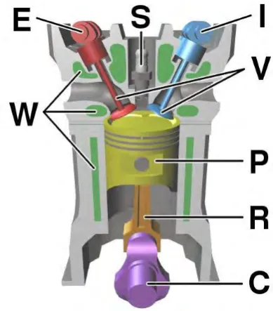
2.1.2 Part of the 4-stroke internal combustion engine and its working principle
[image:21.595.218.413.204.426.2]This is several of the basic important parts of modern automobile engines which are the spark coil, the pistons, the camshaft, the crankshaft, the ECU, the injectors, the spark plugs and the valves (George Alexandrov, Kaitlin Bergin, Rolih Ferdinand, Jeffrey Kowalski and Xiao Ying Zhao, n.d).
Figure 2.1 4 Stroke internal combustion engine basic part
(E) Camshaft of exhaust, (I) Camshaft of intake, (S) Spark plug, (V) Valves, (P) Piston,
(R) Connecting rod, (C) Crankshaft, (W) Coolant flowwater jacket
2.2 Dynamometer
According to (Wright, 2015) on his book “Fundamentals of Medium/Heavy Duty Diesel Engines”, A device that calculate power and torque created by engine is called a dynamometer. It is generally associated with a computer that can compute and analyze every parts of engine operation measured.
9 turbine’s rotor and blades and simulates wind blowing and turning the blades. This is an example of a torque flange mounted dyno, a type of engine dyno, in which the dyno is mounted directly to the shaft of the power source using a torque transducer, or flange. Other types of engine dynos are hydraulic, eddy current, AC engine, and small engine dynos.
Dynamometers are usually useful in design and refinement engine technology. It enable to identify how an engine or its drivetrain needs to be modified or tuned to achieved more efficient power transfer (Wright, 2015).
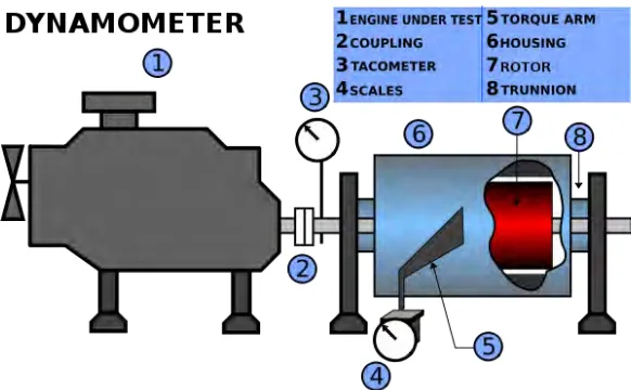
According to (Wright, 2015), there are two types of dynamometer : I. Engine dynamometer
[image:22.595.191.482.358.538.2]The engine dynamometer only calculates engine performance, by removing the engine from the vehicle and mounted onto a special frame. It is directly connected to the engine flywheel and calculates performance independent of the vehicle’s drivetrain, such as losses from transmission or differential.
Figure 2.2 Basic diagram of engine dynamometer
II. Chassis dynamometer
10 Figure 2.3 Basic diagram of chassis dynamometer
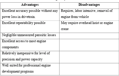
2.2.1 Advantages and disadvantages for Engine dynamometer and Chassis dynamometer
Table 2.1 Engine dynamometer
Advantages Disadvantages
Excellent accuracy possible without any power loss in drivetrain.
Requires, labor intensive, removal of engine from vehicle
Excellent repeatability possible May require overhead hoist or engine crane
Negligible unmeasured parasitic losses Excellent access to most engine
components
[image:23.595.112.524.425.688.2]11 Table 2.2 Chassis Dynamometer
Advantages Disadvantages
Test right in the vehicle Accuracy subject to numerous driveline-loss variables
Access to engine components varies greatly by item and vehicle
Repeatability subject to traction variables
All ancillary electrical items, pumps, etc. are already in place
Significant unmeasured parasitic losses
Well suited for fuel mapping, general tuning, and Hp shootouts
Relatively expensive for level of precision and power capacity May require a pit or lift (for larger-diameter rolls only)
2.2.2 Type of dynamometer principles
I. Water brake dynamometer
It is the most prominent in performance automotive applications. As the engine accelerating on the dynamometer, the rotor rotates inside the housing. The principal is similar with torque converter yet uses water instead of transmission liquid. Therefore, disregarding the way that the rotor and stator are not directly connected, as the rotor starts to rotate, the stator tries to turn with it in a similar direction. Associated with the dynamometer's steel frame on one side and the stator housing on the other, a strain gage keeps the retention unit from turning and calculate torque.
II. Eddy-current (EC)