A 16-BIT CORDIC ROTATOR FOR HIGH-SPEED WIRELESS LAN
Koushik Maharatna1, Alfonso Troya2, Swapna Banerjee3, Eckhard Grass2, Miloš Krsti 2
1 Dept. of EE, University of Bristol, UK, [email protected] 2 IHP, Frankfurt (Oder), Germany, {troya, grass, krstic}@ihp-microelectronics.com
3 Dept. of E & ECE, IIT Kharagpur, India, [email protected]
Abstract – In this paper we propose a novel 16-bit low power CORDIC rotator that is used for high-speed wireless LAN. The algorithm converges to the final target angle by adaptively selecting appropriate iteration steps while keeping the scale factor virtually constant. The VLSI architecture of the proposed design eliminates the entire arithmetic hardware in the angle approximation datapath and reduces the number of iterations by 50% on an average. The cell area of the processor is 0.7 mm2 and it dissipates 7 mW power at 20 MHz frequency.
Keywords – CORDIC, NCO, Synchronization, low power, WLAN.
I. INTRODUCTION
OFDM-based high-speed Wireless LAN (WLAN) systems are currently in the focus of research and development. However, the hardware cost of such systems is quite high and innovative techniques have to be used to design the critical functional blocks in order to satisfy the timing and power constraints as well as to minimize the overall circuit complexity and cost. One such critical functional block is the CoOrdinate Rotation DIgital Computer (CORDIC) that can be used for the frequency offset correction of the input data during synchronization at the receiver. In this case, the forward rotation mode of the CORDIC is utilized which essentially works as a Numerically Controlled Oscillator (NCO). Though it offers an elegant solution, the classical CORDIC algorithm has several shortcomings, which inspired many researchers to look into the development of high-performance CORDIC algorithm and its efficient implementation [1 – 6]. However, the algorithmic level speed limit of CORDIC as well as the required scale factor compensation are problems which restrict the application range of this circuit.
In this paper we describe a novel CORDIC rotator that is used for the synchronizer unit in a project that aims at the implementation of single-chip modem for IEEE 802.11a standard [7]. Though according to the specification of the project we design a 16-bit CORDIC processor that can operate in the forward operation mode only, the method can be generalized for any arbitrary wordlength. In essence, the current work is based on a scaling free CORDIC algorithm proposed earlier by the authors [8, 9]. The CORDIC rotator proposed here is virtually scaling free (needs a scaling by
1/√2 or 1) and has the convergence range over the entire coordinate space. It converges to the target angle by adaptively choosing the actually needed iteration steps only, while skipping the other not actually needed iteration steps. This adaptive selection does not have any impact on the final scale factor. Based on this algorithm, we propose a design of a low power 16-bit pipelined CORDIC rotator that eliminates the entire arithmetic processing and subsequent circuitry along the angle approximation (or z) datapath and on an average saves 50% iterations without compromising the accuracy. The rest of the paper is structured as follows: Section II describes the theoretical formulation of the algorithm while the VLSI implementation is described in Section III. The performance evaluation is done in Section IV and the conclusions are drawn in Section V.
II. THEORETICAL GROUNDWORK
In essence, this work is based on a scaling free CORDIC algorithm proposed by the authors that eliminates the problem of scale factor compensation [8, 9]. In this algorithm the vector is rotated only in one direction in steps of very small angles i so that the magnitude of the vector remains preserved at each step of elementary rotation. The angles i are expressed as,
sin( i) i = 2
−i (1)
With this consideration, the working equation of the scaling free CORDIC at the ith iteration becomes,
+ − − − −
− +
− − = + +
i y
i x i
i
i i
i y
i x
) 1 2 ( 2 1 2
2 ) 1 2 ( 2 1
1
1 (2a)
i i
i z
z+1= −2− (2b)
Because of the 1st order approximation used in equation (1), the allowed values of elementary rotational index (iteration index) i are,
(b − 2.585) / 3 = p ≤ i ≤ b−1 (3) where b is the wordlength. Though this approach eliminates the scale factor compensation problem, its convergence range is very small. In this work we extend its convergence over the entire coordinate space by employing a technique called domain folding.
We first divide the first quadrant into four domains namely A∈[0, π/8), B∈[π/8, π/4), C∈[π/4, 3π/8) and D∈[3π/8, π/2]. In each of these domains the target angle θ can be redefined in terms of another angle φ bounded in the interval [0, π/8] by the following equations,
θ = φ , in domain A (4)
θ = π/4 −φ , in domain B (5) θ = π/4 + φ , in domain C (6) θ = π/2 −φ , in domain D (7) Thus, the CORDIC rotator operation on an input vector [x y]T in different domains can be expressed in terms of φ as follows (considering clockwise rotation),
− = y x y x fA fA φ φ φ φ cos sin sin cos (8) + − − − + = y x y x fB fB ) sin cos ( ) sin (cos ) sin cos ( ) sin (cos 2 1 φ φ φ φ φ φ φ φ (9) − + − + − = y x y x fC fC ) sin cos ( ) sin (cos ) sin cos ( ) sin (cos 2 1 φ φ φ φ φ φ φ φ (10) − = y x y x fD fD φ φ φ φ sin cos cos sin (11)
where xf* denotes the final vector resulting from a CORDIC rotator operation with target angles lying in a certain domain indicated by ‘*’.
Now denoting [x1+ y1+]T and [x1
− y1−]T as the result of
CORDIC rotation for angles φ and −φ respectively, equations (8) to (11) can be written as,
−
=x1
xfA yfA = y1− (12)
] 1 1 [ 2 1 + ++
= x y
xfB [ 1 1]
2 1
+ ++ −
= x y
yfB (13)
] 1 1 [ 2 1 − −+
= x y
xfC [ 1 1]
2 1
− −+ −
= x y
yfC (14)
+
= y1
xfD yfD =−x1+ (15)
Hence, using the above equations, the CORDIC rotator operation with target angles lying in any domain in the first quadrant can be computed from the results of the CORDIC rotation with the modified target angle φ (bounded in the interval [0, π/8]). By exploiting the symmetry of the co-ordinate axes, this technique can be extended to carry out CORDIC rotator operations with target angles lying in other quadrants as well with minimal extra hardware overhead. As a result, a CORDIC having a convergence range of [0, π/8] is sufficient to cover the entire coordinate space. It is to be noted that for target angles lying in domains B or C, we require a fixed scale factor of 1/ 2 that is absolutely
independent of the number of iterations executed. On the other hand, for the angles lying in domains A or D, no scaling is required. We call this technique domain folding since in this formulation all the domains are effectively folded back to domain A.
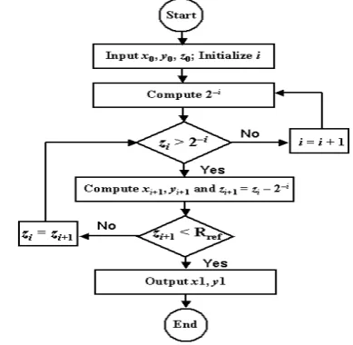
To enhance the convergence range of the scaling free CORDIC to π/8, we propose the greedy algorithm shown in Figure 1 which essentially selects only the absolutely needed elementary rotational steps in an adaptive manner. Rref in Figure 1 denotes a user-defined accuracy.
[image:2.595.329.524.375.565.2]III. VLSI IMPLEMENTATION AND RESULTS In principle, our design consists of three basic sections, viz., the sign/domain detection circuitry, the basic CORDIC rotator having a convergence range [0, π/8], and the output circuitry. The design specification for our system needs a 16-bit CORDIC rotator. In our formulation the maximum target angle φ to be computed is π/8, which can be expressed as 0001100100100010 with an error of O(2−16), where we consider the definition of decimal 1 to be 0100000000000000. Thus, for representing the absolute value of any angle lying in our modified convergence range one can omit the 3 MSB and use the 13 LSBs. We use this fact to reduce the arithmetic computation in the z datapath.
Fig. 1. The proposed greedy algorithm.
A. Sign / Domain detection circuitry
characterize quadrant and domain of the original target angle.
B. Basic pipelined CORDIC rotator
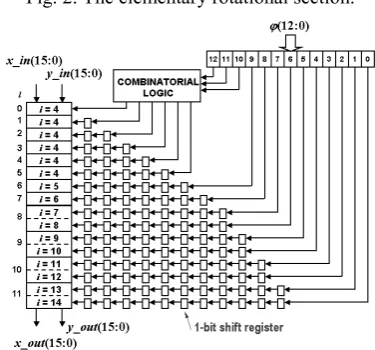
The elementary rotational section used here is shown in Figure 2 [8], which is essentially derived from equation (2a). For a pipeline implementation, each of these sections requires two adders more compared to that of the conventional CORDIC. However, for the elementary rotational sections corresponding to i ≥ 7, a right shift by (2i+1)-bit essentially results in a machine zero or retention of the sign bit only and thus, the extra adders can be omitted for those stages. The allowed values of iteration in the present case are {4, 5, …, 15} (p = 4 from equation (3)). However, a right shift by 15-bit once again results in the retention of the sign bit only and thus for practical purpose the i = 15 stage can be omitted. We will show later that this does not significantly affect the accuracy.
In our implementation, we have used the i = 4 elementary rotational stage six times whereas, the stages corresponding to i = 5…14 are used once each. With this arrangement the maximum angle that can be computed is 25°, therefore covering our convergence range. To make the pipeline completely balanced in terms of operation speed, we concatenate the elementary rotational sections corresponding to i = (7, 8), (9, 10), (11, 12) and (13, 14), where the sections within the parenthesis form a single pipeline stage. Thus, the basic CORDIC pipeline becomes 12 stages long, with the hardware complexity of each of them being equivalent to four 16-bit adders. The signals quad and domain are transferred synchronously between two successive stages of the pipeline in a local register transfer manner. These signals act as a token attributed to the data in different sections of the pipeline carrying the information about the initial quadrant and domain of that particular data.
As it has been mentioned earlier, in this algorithm we approach the target angle by rotating the vector in one direction only. Thus, in essence, we are approximating the final target angle as a pure summation of 2−i. As a result, the appropriate rotational sections to be activated for a particular target angle have a one-to-one correspondence with the position of a logic ‘1’ in the 13-bit unsigned representation of φ. As an example, let us consider φ = 20°
(0.349 radian). The unsigned representation of this angle is 1011001010111. To achieve this target angle, the rotational sections to be activated are governed by the algorithm described in Figure 1. In the present example these are i = 4, 4, 4, 4, 4, 5, 8, 10, 12, 13 and 14, whereas the deactivated elementary rotational sections are simply bypassed. The number of active i = 4 stages is obtained after decoding the first three Most Significant Bits (MSB) in φ (12th, 11th and 10th bits). Hence, the combinatorial logic shown in Figure 3 is a simple digital decoder. In the previous example, we found the first three MSBs to be 101, which corresponds to
decimal 5. Note that the case in which all three MSBs are ‘1’ will never occur.
[image:3.595.335.523.419.594.2]To keep the pipelined operation intact, we feed the individual bits of the 13-bit unsigned representation of φ to the appropriate elementary rotational sections as an enable signal for that particular section through an array of shift registers. The number of the shift registers is chosen in such a manner that the appropriate section gets enabled at the appropriate clock cycles. The complete architecture is shown in Figure 3 where the dotted lines indicate the concatenated elementary rotational stages. This arrangement essentially mimics the search algorithm shown in Figure 1 and eliminates the comparison of zi with 2−i and Rref and the associated computation of the new residual angle (zi+1). Thus, the attendant hardware in the angle approximation datapath can be omitted completely. It is to be noted that in the conventional CORDIC algorithm this simple arrangement for eliminating the z datapath cannot be adopted directly since the target angle is approximated by to-and-fro motion of the vector.
Fig. 2. The elementary rotational section.
Fig. 3. The architecture of the basic CORDIC rotator.
C. The output unit
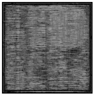
or passes it to the primary output registers. All the operations in this unit are completed in one clock cycle. The complete processor is modeled in VHDL and is synthesized using IHP 0.25 µm BiCMOS technology. The cell area of the processor core occupies 0.7 mm2 which is equivalent to 24.7 k inverter gates in this technology. After layout, the silicon area is 0.9 mm2. To our knowledge, this is the smallest pipelined CORDIC rotator reported so far. The power dissipation estimated by the Synopsys Design Analyzer tool at the intended 20 MHz operation frequency is 7 mW. The latency of the processor is 14 clock cycles and the throughput is 1 set of results per clock cycle. These figures show that the processor consumes little silicon area and is suitable for high-speed low power applications. The layout of the processor core is shown in Figure 4.
Fig. 4. The layout of the CORDIC rotator core.
IV. PERFORMANCE EVALUATION
A. Area
[image:4.595.328.529.329.489.2]The silicon area of the proposed design compared to some existing designs is shown in Table 1 considering 16-bit implementation. To make the comparison uniform, the scaling circuitry is not considered here, since it is not reported in [4] and [5]. It can be seen clearly that the hardware requirement of the proposed one is less than the others. It is also evident that the hardware cost of the complete architecture is 22% less in terms of adders and about 53% less in terms of registers compared to that of the conventional CORDIC.
Table 1
A comparison of the proposed processor with some other similar processors (16-bit implementation).
# full adders # registers Conventional 768 768 Dawid [4] 1,280 1,984 Antelo [5] 896 1,632
Proposed 768 533
B. Number of iterations
Figure 5 shows the required number of iterations for a pseudo-random sequence of target angles in the range
[0, π/8]. On an average, the proposed processor saves 50% computations. The worst-case iteration number is 15, which occurs for the angle 21.482°.
Fig. 5. Required iterations for angles in range [0, π/8].
C. Accuracy
The error in the x and y datapaths is plotted in Figure 6. Here, the actual VHDL model is compared with a Matlab model of an ideal CORDIC. Figure 6 shows that the worst-case error in the x and y datapaths occurs at the 11th bit position which is similar to that of the conventional CORDIC having 16-bit wordlength.
Fig. 6. Bit error position: a) x datapath; b) y datapath.
D. Power
The complete elimination of the z datapath in conjunction with the reduction of the total number of iterations makes the proposed scheme highly suitable for low power applications. This fact is also reflected in our synthesis results which show that the proposed processor consumes 7 mW power at 20 MHz operating frequency and 2.5 V power supply.
E. General discussions
[image:4.595.71.258.582.677.2]the variable number of iterations incurs problems, when using the algorithm in the feedback mode, i.e. not pipelined. In that case, the performance is governed by the worst case delay and not by the average case delay. However, using asynchronous design or a Globally Asynchronous Locally Synchronous (GALS) methodology, one can once again get the advantage of average case performance even in the feedback mode. In the synchronous mode, though the circuit operates with the worst case delay, still power saving could be quite significant.
Another problem in the proposed scheme is that the selection of the largest elementary angle depends on the wordlength (equation (3)). This angle becomes increasingly smaller as the wordlength increases. Consequently, one needs to incorporate more sections of this elementary angle in the pipeline. As a result, the conventional CORDIC is expected to outperform the proposed one in terms of hardware requirement when the wordlength reaches 20-bit. However, in that case, a hybrid scheme can be adopted to bring down the hardware cost. One may use some conventional CORDIC iteration (only unidirectional) to bring down the residual angle within the range of the scaling free CORDIC iterations and then employ the proposed algorithm. In such a case, the scale factor compensation circuitry required for those conventional CORDIC sections has to be integrated into the corresponding elementary rotational sections to avoid the generation of a final scale factor and to maintain the virtually scaling free property of the proposed algorithm. However, in general, hardware implementations with 16-bit wordlength encompass a vast application space and for that the proposed CORDIC rotator shows significantly improved performance compared to the conventional CORDIC.
V. CONCLUSIONS
In this article, we present a novel algorithm and architecture of a special rotational CORDIC processor that operates only in the circular coordinate space and has an unlimited angular convergence range. The algorithm adaptively selects the appropriate iteration steps and thus, converges to the target angle executing a minimum number of iterations. On an average, the number of iterations in the proposed method is about 50% less compared to that of the conventional CORDIC processor without compromising the accuracy. The novel property of the proposed algorithm is that, unlike the conventional and previously reported CORDIC, the adaptive selection of the iteration steps has no influence on the final value of the scale factor (1 or 1/√2 depending on the target angle). Thus, unlike the previously published CORDIC rotator architectures, in our scheme, it is possible to bypass the actually not needed iteration steps while keeping the scale factor virtually constant.
Another novel feature of our algorithm and architecture is that in this scheme it is possible to eliminate all arithmetic computations and associated hardware in the angle
approximation datapath. This also makes the CORDIC rotator operation faster and more economic. The hardware cost of the complete architecture is 22% less in terms of adders and about 53% less in terms of registers compared to that of the conventional CORDIC. These features show the advantage of the proposed CORDIC rotator compared to the conventional CORDIC architecture. Moreover, the hardware requirement for the pre-processing unit (sign/domain detection circuitry) is very small compared to that used for the other argument reduction techniques. The reduction of area and the arithmetic computation suggests that the power efficiency of the proposed structure is better than the conventional CORDIC.
Based on this algorithm, a 16-bit pipelined CORDIC processor core is designed using IHP in-house 0.25 µm BiCMOS technology. The measurement results show that the processor consumes little silicon area and is suitable for high-speed low power applications. Currently, this CORDIC processor is used as part of the Baseband Processor core in a project aiming to design a single-chip wireless modem compliant with the IEEE 802.11a standard [7].
REFERENCES
[1] N. Takagi, T. Asada and S. Yajima, “Redundant CORDIC methods with a constant scale factor for sine and cosine computation”, IEEE Trans. Comput., vol. 40, no. 9, pp. 989 – 995, Sept. 1991.
[2] J. A. Lee and T. Lang, “Constant-factor Redundant CORDIC for Angle Calculation and Rotation”, IEEE Trans. Comput., vol. 41, no. 8, pp. 1016 – 1025, Aug. 1992.
[3] J. Duprat and J. M. Muller, “The CORDIC Algorithm: New Results for Fast VLSI Implementation”, IEEE Trans. Comput., vol. 42, no. 2, pp. 168 – 178, Feb. 1993. [4] H. Dawid and H. Meyr, “The differential CORDIC algorithm: Constant scale factor redundant implementation without correcting iterations”, IEEE Trans. Comput., vol. 45, no. 3, pp. 307 – 318, March 1996.
[5] E. Antelo, J. D. Bruguera and E. L. Zapata, “Unified mixed radix 2-4 redundant CORDIC processor”, IEEE Trans. Comput., vol. 45, no. 9, pp. 1068 – 1073, Sept. 1996.
[6] A. Madisetti, A. Y. Kwentus and A. N. Willson, “A 100 MHz, 16-b, direct digital frequency synthesizer with 100-dBc spurious-free dynamic range”, IEEE J. Solid-State Cir., vol. 34, no. 8, pp. 1034 – 1043, Aug. 1999.
[7] M. Krstic, A. Troya, K. Maharatna and E. Grass, “Optimized Low-Power Synchronizer Design for the IEEE 802.11a Standard”, in Proceedings of the IEEE ICASSP’03, Hong Kong, P.R. of China, vol. II, pp. 321 – 324, April 2003. [8] E. Grass, B. Sarker and K. Maharatna, “A Dual Mode
Synchronous/Asynchronous CORDIC Processor”, in
Proceedings of the 8th IEEE International Symposium on Asynchronous Circuits and Systems, Manchester, U. K., pp. 76 – 83, April 2002.