This is a repository copy of
High speed imaging and Fourier analysis of the melt plume
during close coupled gas atomisation
.
White Rose Research Online URL for this paper:
http://eprints.whiterose.ac.uk/84393/
Version: Accepted Version
Article:
McCarthy, IN, Adkins, NJ, Aslam, Z et al. (2 more authors) (2009) High speed imaging and
Fourier analysis of the melt plume during close coupled gas atomisation. Powder
Metallurgy, 52 (3). 205 - 212. ISSN 0032-5899
https://doi.org/10.1179/174329409X409549
[email protected] https://eprints.whiterose.ac.uk/
Reuse
Unless indicated otherwise, fulltext items are protected by copyright with all rights reserved. The copyright exception in section 29 of the Copyright, Designs and Patents Act 1988 allows the making of a single copy solely for the purpose of non-commercial research or private study within the limits of fair dealing. The publisher or other rights-holder may allow further reproduction and re-use of this version - refer to the White Rose Research Online record for this item. Where records identify the publisher as the copyright holder, users can verify any specific terms of use on the publisher’s website.
Takedown
If you consider content in White Rose Research Online to be in breach of UK law, please notify us by
High speed imaging and Fourier analysis of
the melt plume during close coupled gas
atomisation
I. N. McCarthy
1, N. J. Adkins
2, Z. Aslam
1, A. M. Mullis
*
1and R. F. Cochrane
1A high speed digital analysis technique has been used to study the atomisation plume of a
superheated sample of Ni Al in a close coupled gas atomiser. The atomisation, incorporating a
generic melt nozzle and die design was captured using a Kodak high speed digital analyser at
a frame rate of 18 k frames per second. The resulting 65 536 frames were then analysed using a
specially designed routine, which calculates values of optical brightness and position of the
intensity maximum for all frames and performs Fourier analysis on the sequence. The data
produced from this analysis show that the plume, pulses at low frequencies (
,
25 Hz) and
precesses at higher frequencies (
y
360 Hz) around the atomiser’s centreline. To aid investigation
into the origins of this precession and other phenomena it was decided to conduct further
experiments using an analogue system. The analogue atomiser reproduces the important
features of the full atomiser but instead of atomising molten metal, the analogue system atomises
water, providing a quick and easy way of testing the effects of changing parameters. Using this
system it was found that the precession of the melt plume is independent of the atomiser’s gas
inlet pressure but strongly dependent on both the die and melt nozzle’s geometry.
Keywords:Close coupled gas atomisation, High frame rate image capture, Gas plume, Atomisation nozzle geometry, Fourier analysis, Ni Al
Introduction
Close coupled gas atomisation is a commercial techni-que for producing metal powders, whereby a molten metal stream is broken into small droplets by its interaction with a high velocity gas. These droplets then solidify to form a fine powder. Owing to the small particulate size of atomised powders they have extremely high cooling rates. This rapid solidification produces materials with unique characteristics unseen in their conventionally cooled counterparts. These include refinements or changes in microstructure, increased homogeneity and enhanced structural and chemical properties.1 However, due to the complex nature of the interactions seen in close coupled gas atomisation, and the commercial sensitivity of much of the research, a thorough knowledge of the physical mechanisms leading to the break-up of the melt is currently lacking in the literature base. This has meant that atomisers are often run in a less than scientific manner, instead using experience alongside trial and error to produced desired powders.2
This is not to say that there has not been great improvement in understanding. Early work into gas
atomisation focused on empirical correlations between the mean particle size and a host of parameters, includ-ing, gas flowrate, gas pressure and melt flowrate to name but a few.3,5 The most famous example of such early work is undoubtedly the gas to metal ratio, or GMR, investigated by Lubanska.4In his work Lubanska noted a relationship between median particle size D and the GMR
D~K=(GMR)1=2 (1)
whereKis a constant whose value is system dependent. Improvements have also been made in the efficiency of close coupled gas atomisation. This has been achieved by improving the coupling of the melt and gas flows and has the effect of reducing the mean particle size.6,7 Despite such improvements the standard deviation of powders produced in most atomisers is quite large, often 2?0 and above. This means a large amount of sieving and filtering is required to give a finished product, making the cost of the atomised powder high.
More recently high speed observation and analysis of the atomiser’s melt plume has revealed several phenom-ena which are likely to affect the mean particle size and the standard deviation.8,10It has been noticed by Ting
et al.10that the melt plume shows an irregular low fre-quency pulsation in the amount of melt material emitted from the nozzle. This has the effect of varying the GMR on short time scales, increasing the spread of particle sizes. The model proposed by Ting to explain this
1Institute for Materials Research, University of Leeds, Leeds LS2 9JT, UK 2CERAM Research, Queens Road, Penkhull, Stoke on Trent ST4 7LQ, UK
phenomenon suggests that the oscillation is caused by the gas flow field fluctuating from open to closed wake structures due to the presence of the melt material.
Using Fourier analysis alongside high speed imaging Ting has also shown that there exists a much higher speed precessional movement of the melt in a cone shape around the melt nozzle’s central axis. An early postula-tion for the mechanism of this mopostula-tion has been pro-posed by Anderson,9who suggests that it may be due to the uneven melt filming of the melt nozzle tip. If this is indeed the case then it may well impact negatively on the powders produced.
The work covered in this paper uses the authors’ unique Fourier analysis technique alongside a high speed digital analyser operating at 18 000 frames per second to study the atomisation of a 6 kg batch of superheated Ni31 5Al68 5alloy. Metal atomisation takes place on the pilot plant atomiser situated at CERAM research. Analysis of this data has been aided by the use of an analogue atomiser that atomises a stream of water using zero grade air in a laboratory environment.
Experimental
Metal atomisation
Atomiser design
The close coupled gas atomiser, based at CERAM research, uses a straight, 18 hole discrete jet die, inclined to an apex angle of 45uand a melt nozzle with an apex angle matching that of the gas jets (Fig. 1). The die is machined from brass and the melt delivery tube is made from hot pressed boron nitride. Although research into comparable designs has shown this set-up to be relatively inefficient in the atomisation of various metals, the simplicity of numerically modelling such a system makes this design attractive, as does the fact that due to the simple geometry of the jets it is able to operate over a large range of pressures, allowing us to investigate the atomisation as a function of pressure.
Materials
A superheated 6 kg batch of 50 50 w/o Ni Al was atomised at a pressure of 3?5 MPa using argon as the impinging gas. The argon was supplied via a reservoir of cylinders; each pressurised to 20?0 MPa, connected together using armoured steel hosing.
Atomisation experiment
The melt, a batch of 50 50 w/o Ni Al was induction melted in a crucible to a temperature of 1813 K (corresponding to a superheat of 200 K) before being injected into the atomisation chamber at a pressure of 0?4 KPa (giving a melt flowrate of 15?75610 3kg s 1).
When atomising with argon gas at 3?5 MPa this gives an average GMR of 0?324.
The high temperature of the melt means that it is able to luminese sufficiently to allow imaging to be conducted without an external light source. Imaging of the atomisation happened under steady state conditions. Details of the imaging and analysis processes are outlined below.
Analogue atomisation
Atomiser design
To aid the analysis of the system described above, an analogue version was constructed which models the features seen in the full atomiser. To allow easy com-parisons to be made this system uses identical melt nozzle and die geometries to the full gas atomiser. For simplicity both die and melt nozzle in the analogue system are produced in brass.
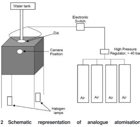
[image:3.595.302.529.47.252.2]A schematic of the analogue system can be seen in Fig. 2. The melt material used is water and is supplied via a regular heating pump and header tank configura-tion. The pump supplies the water at a constant pressure ofy0?4 KPa, replicating the pressure which the molten metal melt is under in the full atomiser. The argon gas supply has been replaced with four 80 L bottles of zero grade air pressurised to 20 MPa. The inlet regulator is capable of supplying the gas at pressures of up to 6?0 MPa to the die. The die and nozzle system are situated in a Perspex cubicle, allowing the atomised mist to be contained. In the case of analogue atomisation, lighting is provided by two 1?2 kW halogen sources mounted to the bottom of the unit. To provide an acceptable amount of contrast in the images all sides of the cubicle which houses the atomiser are blacked out, apart from a small porthole where the camera is situated.
Materials
Initial runs using the analogue atomiser used plain water as the melt material and zero grade air as the impinging gas. However owing to the non-prefilming nature of the initial run it was decided that all further runs should be conducted with the surfactant sodium dodecyl sulphate added to the melt at a concentration of 0?1 g L 1, in a bid to aid melt tip prefilming.
1 Schematic of die and melt nozzle configuration
2 Schematic representation of analogue atomisation
Analogue experiments
Once running as intended a number of studies were conducted using the analogue set-up. First it was decided to investigate the effects that changing the gas inlet pressure may have on the atomisation process. This was carried out with the same basic die and melt nozzle geometries used in the metal atomisation. A series of runs was conducted at varying gas inlet pressures: from 0?5 to 4?0 MPa at 0?25 MPa intervals. The images taken were then subsequently analysed using a specially design Fourier analysis routine.
A series of prototypes have also been made, to allow us to elucidate the effects that changing geometry of components may have on the movement seen in the melt plume.
Two identical dies have been produced by different machining methods to see to what extent the accuracy of machining affects the results. The two dies, both 18 hole straight sided dies, inclined to an apex of 45u are both made from brass. One was produced by conventional drilling and the other was produced by spark erosion. Spark erosion offers a higher degree of accuracy than regular drilling. Tests with otherwise identical compo-nents and parameters were conducted with both dies to allow comparisons to be made.
The four melt delivery tubes tested are schematically pictured in Fig. 3. Type 1 is a simple flat nozzle with a straight tube, identical to the nozzle used in the metal atomisation experiment. The flat section of this design is 1?45 mm wide. The Type 2 delivery tube has a flared profile, angled at 30u. The flat section in this case has been reduced to 0?7 mm in width. Type 3 is almost identical to Type 2, apart from that the flared design now tapers to a sharp edge, eliminating the flat section altogether. The type 4 melt nozzle has a hemispherical cross-section with a radius of 2?5 mm. Like the Type 3 melt nozzle, this design also has no flat section. Testing of these designs took place at 4?0 MPa using the die produced by spark erosion.
Imaging and analysis methods
High fame rate acquisition
Imaging of the melt during atomisation was conducted using a Kodak Ektapro 4540mx high speed digital motion analyser. When fitted with a high magnification optical lens it is able to produce a 5 cm2 image at a
distance of 25 cm from the subject. The data transfer rate of the system allows eight bit grey scale Tiff images to be produced and stored on 1 GB of fast solid state memory at rates of upto 18 000 frames per second. The frame rate achievable is dependent on the size of the individual image. The highest frame rate is used in this current study, corresponding to a frame size of 256664
pixels. The total running time of each capture is 3?64 s. The individual sequential images were converted into a movie format for further study using Adobe Premier (a trademark of Adobe Systems Inc.) software.
Frequency data are produced from the Tiff images by running them through a specially designed MATLAB (a trademark of the MathWorks Inc.) script. The script adopts a Fourier method to analyse frequencies seen in intensity and position.
Fourier analysis
The first step in the Fourier technique adopted defines a 4 pixel high window which spans the entire length of the frame, denoted by the rectangle in Fig. 4. This allows the distribution of material passing through the frame to be analysed.
The average grey scale intensity seen in the denoted frame at a given time is calculated using the equation
-I~ 1 64
X64
j 1
Ij (2)
As the intensity is a direct measure of the amount of material seen in each frame fluctuations in this value indicate a pulsation of the amount of melt material seen in the selected frame. The other statistic calculated for each of the images is the weighted average of the melt plume centre position
-j~ P64 j 1
Ij|j
P64 j 1
Ij
(3)
This value correlates to the physical centre of the atomisation spray cone. A value of -j~1 implies the centre is at one extreme of the frame and j-~64 is at the other extreme.
3 Geometries of investigated melt nozzles
Plotting the two statistics against time (or frame number) shows the frequencies with which the values of
-I and -j fluctuate. To display the values of these frequencies and their relative spectral powers the MATLAB script outputs a fast Fourier transform (FFT) of both I-and-j.
Results
Metal atomisation
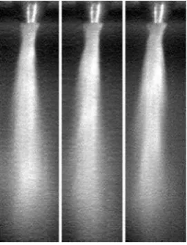
Images produced by the high speed analyser can be seen in Fig. 5. Note that the only light seen in the image is the radiant light given off by the metal. There is clearly a lot of movement within the plume over the whole recording. The whole plume appears to oscillate across the width of the image. A pulsation of material was also been noted, starting from the melt nozzle and moving along the length of the plume. This happens at semiregular intervals.
The time series from which the Fourier spectra are calculated can be seen in Fig. 6. The time series of intensity (Fig. 6a) shows a low frequency, with a higher frequency component superimposed upon it. The time series of the melt centre position (Fig. 6b) shows an absence of the low frequency but a prevalent high frequency component. The values of these frequencies, along with there relative spectral power can be seen in the FFT graphs (Fig. 7).
The low frequency component of the intensity fluctuations has significant power and comprises many frequencies. The main power occurs at 2?2, 2?7, 4?1, 5?5, 8?8 and 15?1 Hz. The presence of a large number of other frequencies possibly points to these oscillations
5 Consecutive images of atomisation of Ni Al, noting
luminous nature of melt
6 Time series ofaintensity andbmelt centre position of initial Raney nickel atomisation
being chaotic. The high frequency seen in both FFTs is very sharp peaks centred on the same value,y360 Hz. Close examination of small sections of the times sequences showed that the high speed oscillation seen is unrelated to the shutter speed of the high speed analyser.
[image:6.595.357.493.50.228.2]Analogue atomisation
[image:6.595.72.530.563.753.2]Figure 8 shows a set of consecutive images taken from the initial analogue run. It is apparent that in this case atomisation takes place in a non-filming manner, as the melt is seen directly exiting the 2 mm melt tube exit. Fourier analysis of the images indicates that this run has very little pulsing behaviour and there is also no precession of the melt plume.
Figure 9 shows a run with identical parameters to the initial run, except that the melt has the surfactant, sodium dodecyl sulphate added to the reservoir at a concentration of 0?1 g L 1. It is clear that prefilming of the melt nozzle is now achieved. The plume now consists of a much finer mist of particles and in general looks similar to the atomisation of Ni Al. Fourier analysis of this run can be seen in Fig. 10. These graphs indicate that both pulsation and high frequency movement now occur. However some differences can be noted between
these plots and the ones produced in Ni Al atomisation. The peak spectral power has moved to a higher value in the atomisation of water and, the peak shows a much more diffuse profile.
Once the analogue atomiser was running as intended, it was decided that a series of experiments should be conducted which would determine how changing var-ious parameters affects the motion of the plume noted by ourselves and several other researchers.9,10The first of these experiments investigated the influence that changing gas inlet pressure may have on the movement of the melt plume. Figure 11 shows the Fourier spectra of intensity at 0?75 and 2?0 MPa. Both spectra shown are practically identical. This appears to be the case across the whole range of pressures tested, all graphs show nearly identical spectra.
The next variable to be investigated was the machin-ing accuracy of the dies. Images of the jet exits of both dies are shown in Fig. 12. The jets of the drilled die show a greater variation, with some having significant eccentricity (the average eccentricity for the machined jets is e 0?92). The spark eroded die has much more uniform gas jets, with an average eccentricity ofe 0?97. The frequency spectra of the dies, given in Fig. 13, show some obvious differences. The die manufactured using spark erosion gives a frequency peak with a much
9 Analogue atomisation conducted with added surfactant
8 Analogue atomisation conducted without added
surfactant
smaller full width half maximum (FWHM). It also confines the low frequency oscillations to a smaller range.
Testing of the four melt nozzle geometries also showed some marked differences in their behaviour. The flat Type 1 nozzle, showed a profile with a very diffuse peak, going up to 3000 Hz, whereas the hemispherical Type 4 nozzle gives a relatively sharp high frequency peak, centred on a value ofy1000 Hz. The spectra corresponding to Type 2 and 3 nozzles are
very similar. The main difference between them is the peak is shifted to a higher frequency in the Type 3 nozzle, the flared nozzle with no flat section.
Discussion
Metal atomisation
The pulsation of melt material noted when viewing the recording has also been verified in the frequency spectra. This melt pulsation happens at frequencies predominately
11 Intensity spectra produced at gas inlet pressures ofa0?75 andb2 MPa
12 Images ofadrilled gas jet andbspark eroded gas jet
in the range of human vision (,25 Hz). This pulsation appears to be the same seen by other researchers.8 However it is interesting to note that this pulsation behaviour is seen in all the authors’ experiments, despite the inlet pressure in some of them being well below what would normally be required for wake closure.10
The lateral high frequency movement noted in the videos is obviously the cause of the high frequency peak in bothI- and-jgraphs. However, it is impossible to tell the true nature of this movement from studying the videos. Is it really a true lateral oscillation or a move-ment like the precessional movemove-ment noted elsewhere?
To help explain the presence of high frequency peaks in both intensity and position spectra, short sections of the corresponding time series were overlapped to see if any phase relation existed between the two.
Overlapping short sections of both time series shows that the high frequency component of the time series is
out of phase by 90uwith respect to each other (Fig. 15). This led to the following conclusion being made about the high frequency movement; the antiphase relationship seen in the time series graphs points to the cone moving in a precessional motion. Figure 16 shows the proposed model for this precessional motion. Maximum values of intensity occur when the melt plume is directed towards the high speed analyser and minimum when facing away (180u from the viewing angle). Whereas maximum and minimum values in melt centre position occur at 90 and 270u.
Analogue atomisation
The absence of precession in the first non-filming run, and the return of the motion in the subsequent run which exhibits filming indicates that this filming aType 1;bType 2;cType 3;dType 4
14 Intensity spectra from four nozzle designs tested
15 Overlapped short sections of intensity and melt centre positon time series showing antiphase relationship
16 Model for precession of atomisation jet giving
behaviour does indeed plays a role in the precession of the plume as postulated by Anderson,9 although the exact mechanism by which this motion occurs is not yet clearly understood.
The similarity of the spectra produced at the broad range of inlet pressures tested has shown that, to within experimental error, the pulsation and precession of the melt plume appears to be independent of the pressure of operation.
It is interesting to see that the manufacturing quality of the gas jets plays such a significant role in both high and low frequency portions of the Fourier spectra. Higher precision engineering leads to a smaller FWHM, meaning the precessional movement seen is more regular, it also seems to help confine the low frequency oscillations linked to the pulsation of the melt. However engineering tolerances have little influence on the value of the peak frequency of precession.
The geometry of the melt delivery tube affects both the peak frequency of precession, and the regularity of the motion. The Type 4 nozzle produces the most regular motion of all the designs tested, and the flat Type 1 nozzle produces the most irregular. The similarity of the Types 2 and 3 nozzle geometries is reflected in their Fourier spectra. The only difference between them is the presence of a lip in the Type 2 design. This seems to increase the angular frequency of the precession. It is unclear at this stage how these differences in spectra would translate into changes in the production of powders. It is hoped to probe this further in future work.
Conclusion
The high speed imaging and subsequent Fourier analysis of the melt plume of a close coupled gas atomiser have helped in improving the authors’ understanding of the interactions seen within the process. The authors have verified the work of Ting et al.,8irregular pulsation of the melt does occur in both the full atomiser and the analogue version and may well be inherent in all close coupled atomisers. Precession of the plume, first noted in Ref. 9, is also observed in the experiments presented here. The lack of precession in the non-prefilming analogue run also supports the claim made by Anderson that this motion is caused due to filming of the melt nozzle.9 However, the exact physical mechan-ism behind this motion is not yet clear. Analogue
investigations have shown that the frequency of this precession is independent of operating pressure but depends to quite a large degree on the geometries and accuracies of the components employed. Dies produced to a higher tolerance give a steadier precession. They also confine the low frequency pulsing to a smaller frequency range. Melt tip design is crucial in the nature of the plume’s movement. The hemispherical Type 4 nozzle gave the sharpest frequency peak, shifted to a higher frequency, whereas the flat Type 1 nozzle gave the most diffuse spectra. It is clear that these changes in design affect the movement seen in the melt plume. What is unclear is how these differences affect the final powders produced. Future work on the full scale atomiser is to be conducted to elucidate this.
Acknowledgement
This work is financially supported by the European Commission (contract number NMP-CT-2004-500635) under the Sixth Framework Programme as part of the IMPRESS project ‘Intermetallic Materials Processing in Relation to Earth and Space Solidification’, coordinated by the European Space Agency. A special thanks also goes to Donald Forder for his help and advice on many technical issues.
References
1. G. Jiang, H. Hemein and M. W. Siegal: ‘Intelligent sensors for atomization processing of molten metals and alloys’, Technical report, 06/1988, Carnegie-Mellon University, Pittsburgh, PA, USA, 1988.
2. A. Lawley: ‘Atomization, the production of metal powders’; 1992, Princeton, NJ, Metal Powder Industries.
3. E. Klov and W. M. Shafer: ‘High pressure gas atomisation of metals’, 57; 1972, Syracuse, Syracuse University Press.
4. H. Lubanska:J. Met., 1970,22, 45 49.
5. I. E. Anderson and R. L. Terpstra: Adv. Powder Metall. Part. Mater., 2001, Part 2, 43.
6. J. Ting, I. E. Anderson, R. Terpstra and J. Mi:Adv. Powder Metall. Part. Mater., 1998, Part 10, 29.
7. S. P. Mates and G. S. Settles:Adv. Powder Metall. Part. Mater., 1996,1, 1?67 1?80.
8. J. Ting, J. Connor and S. Ridder:Mater. Sci. Eng. A, 2005,A390, 452 460.
9. I. E. Anderson, R. L. Terpstra, J. A. Conin and R. S. Figiola: Proc. 3rd Int. Conf. on ‘Spray deposition and melt atomization’, Bremen, Germany, September 2006, University of Bremen, CD proceedings. 10. J. Ting, M. Peretti and W. B. Eisen: Mater. Sci. Eng. A, 2002,