This is a repository copy of Generalisation and optimisation of semi-active, on?off switching controllers for single degree-of-freedom systems.
White Rose Research Online URL for this paper: http://eprints.whiterose.ac.uk/80980/
Version: Submitted Version
Article:
Potter, J.N., Neild, S.A. and Wagg, D.J. (Submitted: 2010) Generalisation and optimisation of semi-active, on?off switching controllers for single degree-of-freedom systems. Journal of Sound & Vibration, 329. 2450 - 2462.
https://doi.org/10.1016/j.jsv.2009.12.011
Reuse
Unless indicated otherwise, fulltext items are protected by copyright with all rights reserved. The copyright exception in section 29 of the Copyright, Designs and Patents Act 1988 allows the making of a single copy solely for the purpose of non-commercial research or private study within the limits of fair dealing. The publisher or other rights-holder may allow further reproduction and re-use of this version - refer to the White Rose Research Online record for this item. Where records identify the publisher as the copyright holder, users can verify any specific terms of use on the publisher’s website.
Takedown
If you consider content in White Rose Research Online to be in breach of UK law, please notify us by
Generalisation and optimisation of
semi-active, on-off switching controllers
for single degree-of-freedom systems
Jack N. Potter1
, Simon A. Neild, David J. Wagg
Department of Mechanical Engineering University of Bristol
Bristol, BS8 1TR, UK
Abstract
This paper examines generalised forms of semi-active switching control
in comparison to the sky-hook semi-active controller. A switching time
con-troller is proposed and analysed, in order to determine the optimal
perfor-mance, with regard to displacement transmissibility, of semi-active switching
control. In addition, the model is also used to assess the optimality of the
sky-hook switching conditions. An analytical solution is then derived for the
optimal switching times. A generalised form of linear switching surface
con-troller is then presented. It is demonstrated that this concon-troller can produce
near optimal performance.
Key words: Semi-active damping, Optimisation, Switching control,
Sky-Hook
∗Address all correspondence to this author.
Email addresses: [email protected](Jack N. Potter),
1. Introduction
Semi-active dampers are a class of energy dissipating device for which
the damping may be controlled in retime. This is achieved by either
al-tering the properties of the damping fluid, as is the case for electro and
magneto-rheological dampers [1], or by actuating mechanical components of
the damper, an example of which is a variable orifice damper. Semi-active
damping, as a method of vibration isolation, has been applied to many
me-chanical and civil engineering systems, see for example [2, 3, 4, 5, 6, 7] and
ref-erences therein. It has been demonstrated to provide considerably improved
performance compared to vibration isolation through passive damping alone.
Approaches to the design of semi-active damping controllers can broadly
be grouped into two forms. The first class applies to systems which may be
accurately described using low order models, such as automotive suspension
systems, for which simple pragmatic control approaches, based on reasoned
physical argument, are often employed, for example [4, 8, 9, 10, 5, 11].
As the complexity of a system increases it becomes difficult to
gener-ate semi-active control policies based on intuitive logic. Consequently for
this second class of system, examples of which include cables, buildings and
bridges, it is common for modified forms of active control design to be applied.
A common example of this class of semi-active control is termed
clipped-optimal control [12, 9]. This employs conventional linear-quadratic regulator
or linear-quadratic gaussian optimal control design based on linear system
models, with the addition of saturation limits due to the physical constraints
on the force that may be generated by the active damper. This
structures, for example see [13, 14, 15, 16, 17, 18].
This paper is concerned with the first class of semi-active controller
de-sign. The most common form of control in this class is called sky-hook
control, which is a control policy that can be applied when a semi-active
damper is connected directly to a mass that is to be isolated. The
sky-hook controller acts to increase damping when the damping force is acting
to dissipate energy from the mass. This paper seeks, through analysis of the
sky-hook controller, to generalise this class of semi-active control in order to
improve performance and better understand the mechanics that determine
the optimality of the control design.
Firstly a review of a sky-hook control law and its behaviour when applied
to a single degree of freedom, base excited suspension system is presented. A
generalised form of switching control based on predetermined switching times
is then proposed. Through simulation of this controller, the optimal
perfor-mance, with regard to minimising displacement transmissibility, of this class
of semi-active control is determined. The sky-hook controller is compared to
these results in order to assess the optimality of the sky-hook switching
con-ditions. An analytical solution for the optimal switching times, based on a
harmonic balance of switching controlled system, is then presented. It is then
shown how the sky-hook controller may be considered to be a specific case
of a generalised form of state-dependent, linear switching surface controller.
Through simulation, optimal switching surfaces are plotted and compared to
the sky-hook surfaces. It is demonstrated numerically that, over a range of
frequencies, the optimal switching surfaces may be approximated using the
2. Sky-Hook control
This paper will consider the semi-active isolation of a single
degree-of-freedom base excited system such as that shown in Fig. 1(a), wherem is the mass to be isolated, k is the suspension stiffness, cis a semi-active damper,
x is the mass displacement and r is the base displacement. The system
is harmonically excited at frequency, Ω, and displacement amplitude, ∆,
such that r = ∆ sin Ωt. Using the standard normalised parameters; natural frequency, ωn =
p
k/m, and damping ratio, ζ =c/(2√km), the equation of motion of the system may be written as follows
¨
x+ 2ζωn( ˙x−r˙) +ω2n(x−r) = 0. (1)
A common strategy for semi-active isolation of a such a system, proposed
by Karnoppet al [8] is to control the damper so that it emulates the behaviour
of an idealised sky-hook system. Such a system, as shown in Figure 1b,
features an inertially grounded passive damper, csky, connected to the mass to be isolated, providing a damping force that is always resistant to the
mass’s velocity. A commonly used semi-active approximation of the sky-hook
system, often referred to as on-off sky-hook control, is to set the damping to
a high level when the damping force is dissipative with regard to the kinetic
energy of the mass and to set the damping to a low level otherwise. For the
system shown in Fig. 1(a), this corresponds to increased damping when the
damper velocity and absolute mass velocity are of the same sign. An on-off
ζ =
ζh, x˙( ˙x−r˙)>0
ζl, else.
(2)
The sky-hook form of control law can be susceptible to chatter [4]. This
occurs when, upon switching from high to low damping at ˙x= 0, the spring force is of opposite sign and of greater magnitude than the low damping force.
Under this condition, the net force on the mass will change direction upon
switching to the low damping state, pushing the velocity back toward zero
and consequently the low to high switching. This results in rapid switching
between the high and low damping levels until the system states are such that
the low damping force is of greater magnitude than the spring force. This
phenomenon is typically associated with large differences between the high
and low damping values. This study will be limited to values of damping for
which chattering does not occur.
A typical plot of displacement transmissibility is shown in Fig. 2, from
which it can be seen that the sky-hook controller performs better than
pas-sive damping at lower frequency but at higher frequency produces higher
transmissibility than the low level passive damping. From this it can be
inferred that the sky-hook controller must be a sub-optimal form of on-off
semi-active control as it fails locate the lower amplitude solution provided by
the always off state.
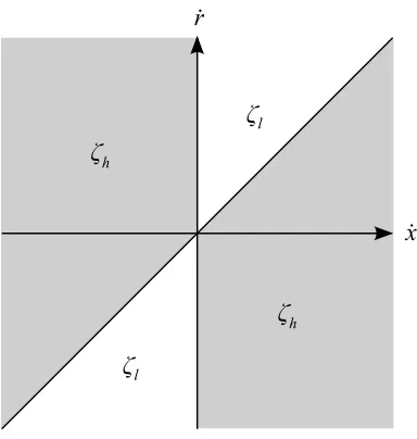
As is clear from Eq. (2), the sky-hook controller switches damping levels
at the zero crossings of the mass and damper velocities. These switching
conditions can be considered as two switching surfaces of ˙x= 0 and ˙x−r˙ = 0 and can be illustrated in a plane of system velocities as shown in Fig. 3. The
is dissipative with regard to the kinetic energy of the mass and is the region
within which the sky-hook control law increases damping.
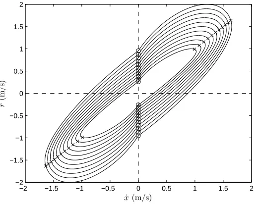
The function of these switching surfaces can be seen by plotting the
steady-state system velocities within this plane, an example of which is shown
in Fig. 4, in which the high to low switching states are denoted by circles
and the low to high switching states denoted by crosses. At each frequency
the velocity trajectory forms a closed orbit, these orbits move outwards from
the centre with increasing frequency. It can be seen that in the steady-state,
the velocity trajectory crosses each of the switching surfaces once every half
period of excitation. Consequently, at a given frequency, the damping level
is switched from high to low and back at fixed times every half period.
By generalising the controller switching conditions, in terms of switching
times and switching surfaces, this study seeks to identify an optimal form of
semi-active switching controller and understand the mechanics which cause
the optimal solution to differ from the sky-hook control scheme.
3. Switching time control
In this section we will examine the response of a generalised form of
semi-active switching control, with arbitrarily defined switching times. The
controller we propose is illustrated in Fig. 5, where the high to low switching
time is denoted by t1 and the low to high switching time by t2. Analysis of this generalised controller form, for all permissible switching times, will allow
the optimal response of this class of switching controller to be determined.
This may then be compared with the response of the sky-hook controller, in
assess the optimality of the sky-hook switching conditions.
3.1. Numerical analysis
Parameters are introduced for frequency normalised width, ¯t, and centre of the damping peak, t0. These are illustrated in Fig. 5 and relate to the switching times as follows
t1 =
(t0−¯t/2 +π)/Ω, t0−t/¯2<0
(t0−¯t/2)/Ω, else
(3)
and
t2 =
(t0+ ¯t/2−π)/Ω, t0+ ¯t/2> π
(t0+ ¯t/2)/Ω, else.
(4)
The parameters,t0 and ¯t, can have values between the limits of zero and
π, and together can describe the system for all permissible switching times. The motivation for introducing these parameters is to aid subsequent analysis
and allow results to be presented in a clearer form.
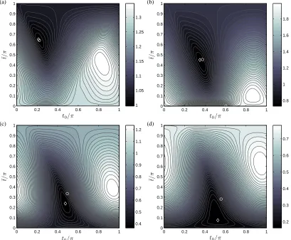
Simulations are computed for a range of t0 and ¯t values between the minimum and maximum values. Typical results are shown in Fig. 6. The
upper edge, ¯t = π, corresponds to the passive high damping response and the lower edge, ¯t = 0, corresponds to the passive low damping response. The minimum steady-state displacement response is denoted by a diamond
and the sky-hook steady-state response is denoted by a circle. Note that
discontinuous along t1 = t2, corresponding to the switch from high to low passive damping either side of the line.
These results show a single, clear minima, revealing the existence of
dis-tinct, optimal switching times at each frequency. A general trend, present
regardless of damping values, is the movement of the minima from high to
low ¯t values with increasing frequency. This shows that to minimise trans-missibility, the high damping level should be applied for smaller proportions
of the excitation period as frequency increases. An analogy may be drawn
between this result and optimisation of an equivalent passively damped
sys-tem, which requires lower levels of damping with increasing frequency to
minimise transmissibility.
Below, and close to, the undamped natural frequency, the sky-hook
switch-ing conditions produce switchswitch-ing times very close to optimal. However as
frequency increases, the sky-hook switching times can be seen to diverge
from the optimal. Most notably, the sky-hook controller results in larger ¯t
values than are optimal. This shows that essentially the sky-hook switching
conditions apply more damping than is necessary, to the detriment of control
performance.
As the numerical results reveal the sky-hook controller to be sub-optimal,
we now seek an analytical solution for the optimal switching times.
3.2. Analytical optimisation
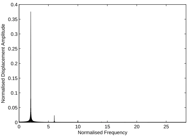
Frequency analysis of the system at optimal switching times, an example
of which is shown in Fig. 7, reveals that the response is dominated by the
excitation frequency. This suggests that a harmonic balance (for example
solution of the switching time controlled system. This technique is now
applied to the system.
Defining,z =x−r, Eq. (1) may be rewritten as
¨
z+ 2ζ(t)ωnz˙+ω 2
nz =−r.¨ (5)
Considering the displacement response only at the excitation frequency, z
may be expressed as follows
z ≈a1cos Ωt+b1sin Ωt. (6)
By substituting Eq. (6) into Eq. (5), multiplying by sin Ωt and integrat-ing across an excitation period, the followintegrat-ing expression is obtained, notintegrat-ing
the orthogonality condition that when integrated the sin Ωtcos Ωt terms are eliminated
π(ω2
n−Ω
2
)b1+ 2ωnΩ 2
b1
Z 2Ωπ
0
ζ(t) cos Ωtsin Ωt dt
−2ωnΩ2a1
Z 2Ωπ
0
ζ(t) sin2
Ωt dt = ∆πΩ2
.
(7)
For t2 > t1, the damping applied by the switching time controller may be expressed as follows, where τ is the modulo of time, t, and a half excitation period, π/Ω
ζ =
ζh, t1 < τ < t2
ζl, else.
(8)
By substituting the switching controller from Eq. (8) into Eq. (7) and
2ωn
Ωζh−ζl
π (t2−t1) +ζl+
ζh−ζl
2π (sin 2Ωt1−sin 2Ωt2)
a1
+
−(ωn2−Ω 2
)/Ω−2ωn
ζh−ζl
π sin
2
Ωt2−sin 2
Ωt1
b1 =−∆Ω. (9)
Similarly, substituting Eqs. (6) and (8) into Eq. (5), multiplying by cos Ωt
and integrating across an excitation period, produces the following
(ω2
n−Ω
2
)/Ω−2ωn
ζh−ζl
π sin
2
Ωt2−sin 2
Ωt1
a1
+2ωn
Ωζh−ζl
π (t2 −t1) +ζl+
ζh−ζl
2π (sin 2Ωt2−sin 2Ωt1)
b1 = 0. (10)
Using Eqs. (3) and (4), Eqs. (9) and (10) may be rewritten as functions of ¯
t and t0, giving
2ωn
ζl+
ζh−ζl
π (¯t−sin ¯tcos 2t0)
a1
−
(ω2
n−Ω
2
)/Ω + 2ωn
ζh−ζl
π sin ¯tsin 2t0
b1 =−∆Ω,
(11)
and
(ω2
n−Ω
2
)/Ω−2ωn
ζh−ζl
π sin ¯tsin 2t0
a1
+2ωn
ζl+
ζh−ζl
π (¯t+ sin ¯tcos 2t0)
b1 = 0.
(12)
a1 =
−2∆ωnΩ3
ζl+
ζh−ζl
π (¯t+ sin ¯tcos 2t0)
4ω2
nΩ
2
ζh−ζl
π t¯+ζl
2
−
ζh−ζl
π
2
sin2¯
t
!
+ (ω2
n−Ω
2 )2
, (13)
and
b1 =
∆Ω2
ω2
n−Ω
2
−2ωnΩζh−π ζlsin ¯tsin 2t0
4ω2
nΩ
2
ζh−ζl
π ¯t+ζl
2
−
ζh−ζl
π
2
sin2¯
t
!
+ (ω2
n−Ω
2)2
. (14)
The steady state displacement amplitude of x, ¯x, may be written as follows
¯
x= (a2
1+ (b1+ ∆) 2
)12. (15)
Substituting Eqs. (13) and (14) into Eq. (15) produces the following
approx-imate solution for the steady-state displacement response of the switching
time controlled system
¯ x2 =
−2∆ωnΩ3
ζl+
ζh−ζl
π (¯t+ sin ¯tcos 2t0)
4ω2
nΩ
2
ζh−ζl
π t¯+ζl
2
−
ζh −ζl
π
2
sin2¯
t
!
+ (ω2
n−Ω
2)2 2 + ∆Ω2 ω2
n−Ω
2
−2ωnΩζh−π ζlsin ¯tsin 2t0
4ω2
nΩ
2
ζh−ζl
π ¯t+ζl
2
−
ζh−ζl
π
2
sin2¯
t
!
+ (ω2
n−Ω
A similar derivation may be performed for t1 > t2, however due to the defi-nitions of the switching times in Eqs. (3) and (4), the solution reached is the
same as that found for the t2 > t1 case.
When compared to the numerical solution of the switching controlled
sys-tem, this analytical approximation is seen to be accurate at higher frequency,
but is less accurate close to and below the undamped natural frequency of
the system. Typical results are shown in Figs. 8 and 9, in which the
numeri-cal minima is denoted by a diamond, the analytinumeri-cally approximated minima
denoted by a cross and the sky-hook solution by a circle. At low frequency
the analytical minima is further from the actual minima than the sky-hook
solution. At higher frequencies, where the sky-hook controller has been seen
to perform poorly, the analytical minima is closer to the actual minima than
the skyhook solution.
By differentiating Eq. (16) with respect to t0 and equating the zero, the following expression for the optimal centre of damping peak, t0opt, as a function of damping width, ¯t, is obtained
t0opt =− 1 2tan −1 ω2
n−Ω
2
4Ω2 +
ζh−ζl
π
2
¯
t2
−sin2¯t+ζl
2ζh−ζl
π t¯+ζl
Ω 2ωn
ζh−ζl
π ¯t+ζl
. (17)
numerically minimising the function with regard to ¯t between the lower and upper bounds of 0 and π respectively.
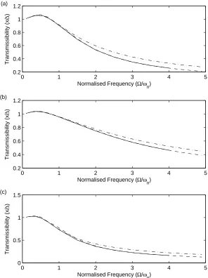
Plots comparing the transmissibilty produced by the optimal and
sky-hook switching times over a range of frequencies and damping values are
shown in Fig. 10. These transmissibilty plots show the performance of the
sky-hook controller to be very close to that of the optimal controller below
the undamped natural frequency. As frequency increases, the performance
of the sky-hook diverges from the optimal.
In addition the analytical optimal solution based on Eq. (16) is shown
(dashed line). It can be seen that this agrees excellently with the numerical
optimal solution at frequencies above the natural frequency with a slight
di-vergence at frequencies below the natural frequency. Note that the numerical
optimal solution is plotted over a smaller frequency range in order for the
analytical optimal solution to be more clearly visible.
4. Switching surface control
The selection of parameters for the switching time controller discussed
in the previous section requires knowledge of the frequency and phase of
excitation. The appeal of the sky-hook form of control law is its simple form,
use of readily measurable states and no requirement for explicit knowledge
of the excitation. We seek to obtain a semi-active switching controller that
is closer to optimal than sky-hook yet retains the practical characteristics of
the sky-hook control form.
As discussed in Section 2 and illustrated in Fig. (3), the sky-hook control
sky-hook controller in this manner naturally presents the question as to whether
better isolation can be achieved by altering these switching surfaces.
For a switching surface to provide the same transmissibility for a given
frequency regardless of amplitude it must be linear. A generalised form of
semi-active switching surface control is expressed in Eq. (18), where αandβ
are the gradients of the linear surfaces. This controller is illustrated with-in
the velocity plane in Fig. 11. The sky-hook controller is a specific case of
this generalised form where β= 1 and α= 0.
ζ =
ζh, ( ˙x+αr˙)( ˙x−βr˙)>0
ζl, else
(18)
For β = 1, the switching surface controller described by Eq. (18) is
equivalent to that proposed by Verros Et al. [20], in which the gradient of
the second switching surface is designed to emulate the behaviour of specific
sky-hook damping coefficients.
The numerical optimisation analysis in Section 3 may be extended to
examine the nature of optimal switching surfaces. The steady-state velocities
of the optimal switching time controlled system are shown in Fig. 12 for
a number excitation frequencies. The trajectories move outward from the
centre with increasing frequency. The states at the high to low switching
times are denoted by circles and the states at the low to high switching times
are denoted by crosses. By plotting at multiple frequencies, these optimal
switching states form optimal switching surfaces within the velocity plane.
These plots reveal that the optimal high to low switching surface is
insen-sitive to damping values and is very close to the sky-hook switching surface of
˙
surface however differs significantly from the sky-hook surface. The optimal
surface is non-linear and appears strongly dependant on the damping values.
Below the natural frequency, the optimal switching surface is close to the
sky-hook surface of ˙x = 0, as is consistent with results from the switching times analysis. As frequency increases, the gradient of the surface diverges
from that of the sky-hook surface.
As this optimal switching surface is non-linear, it is not possible to define a
low to high switching control surface that is optimal regardless of amplitude.
However, as is illustrated in Fig. 13, over limited ranges of frequencies, the
optimal surface may be approximated as linear.
Fig. 14 shows transmissiblity plots of the switching surface controller
expressed in Eq. (18), for β = 1 and varying values of α. These plots show that is is possible to achieve isolation very close to optimal using a linear
switching surface controller. From the low transmissibility obtained using a
range of αvalues, it appears that amplitude trajectory is quite insensitive to switching state close to the optimal surfaces. This aids the process of control
parameter selection by providing relatively large tolerances. Over the range
of damping values examined, an α value of 1 consistently produced isolation close to optimal, representing an improvement over the sky-hook controller
(in which α = 0) especially at frequencies above the natural frequency. It is therefore suggested that this value is an appropriate starting point for
5. Conclusions
This paper has examined the form and behaviour of a sky-hook,
semi-active control law when applied to a single degree of freedom, base isolating
suspension system.
When the system is harmonically excited, in the steady-state, the
sky-hook controller switches damping levels at two distinct times every half
pe-riod of excitation.
By proposing and analysing a generalised switching controller with
ar-bitrarily defined switching times, the optimality of the sky-hook switching
conditions, with regard to minimising displacement transmissibility, is
as-sessed. It is found that below the undamped natural frequency of the
sys-tem, the sky-hook controller is close to optimal but diverges from the optimal
switching times with increasing frequency.
An analytical solution is presented for the optimal switching times, based
on a harmonic balance of the switching controller. For higher frequencies,
where sky-hook control has been shown to be sub-optimal, the analytically
approximated switching times are very close to optimal.
The sky-hook controller is then considered as consisting of two switching
surfaces. Plotting the system states at the optimal switching times for
multi-ple frequencies produces optimal switching surfaces. This reveals one of the
sky-hook surfaces to be very close to optimal. The other optimal switching
surface is shown to be non-linear and dependent on damping values. A
gener-alised form of linear switching surface control is presented. It is shown that,
through appropriate parameter selection (a recommended guideline being
of sky-hook control, can achieve performance very close to optimal.
Acknowledgments
The authors would like to acknowledge the support of the EPSRC. Jack
Potter is supported by an EPSRC DTA.
References
[1] B. F. Spencer-Jr., S. J. Dyke, M. K. Sain, and J. D. Carlson.
Phe-nomenological model for magnetorheological dampers. Journal of
Engi-neering Mechanics, 123(3):230–238, 1997.
[2] Seung-Bok Choi, Moo-Ho Nam, and Byung-Kyu Lee. Vibration Control
of a MR Seat Damper for Commercial Vehicles. Journal of Intelligent
Material Systems and Structures, 11(12):936–944, 2000.
[3] Chun-Yu Lai and W.H Liao. Vibration Control of a Suspension
Sys-tem via a Magnetorheological Fluid Damper. Journal of Vibration and
Control, 8(4):527–547, 2002.
[4] Y. Liu, T. P. Waters, and M. J. Brennan. A comparison of semi-active
damping control strategies for vibration isolation of harmonic
distur-bances. Journal of Sound and Vibration, 280(1-2):21–39, February 2005.
[5] Mehdi Ahmadian and Christopher A. Pare. A Quarter-Car
Experimen-tal Analysis of Alternative Semiactive Control Methods. Journal of
[6] R.S. Prabakar, C. Sujatha, and S. Narayanan. Optimal semi-active
preview control response of a half car vehicle model with
magnetorhe-ological damper. Journal of Sound and Vibration, In Press, Corrected
Proof:–, 2009.
[7] Jeong-Hoon Kim and Chong-Won Lee. Semi-active damping control of
suspension systems for specified operational response mode. Journal of
Sound and Vibration, 260(2):307–328, February 2003.
[8] Crosby M. J. Karnopp, D. C. and R. Harwood. Vibration control
us-ing a semi-active force generator. Trans. ASME, J. Eng. for Industry,
96:2:619–626, 1974.
[9] Y. Shen, M. F. Golnaraghi, and G. R. Heppler. Semi-active
vibra-tion control schemes for suspension systems using magnetorheological
dampers. Journal of Vibration and Control, 12(1):3–24, January 2006.
[10] G. Z. Yao, F. F. Yap, G. Chen, W. H. Li, and S. H. Yeo. Mr damper
and its application for semi-active control of vehicle suspension system.
Mechatronics, 12(7):963–973, September 2002.
[11] L.V.V. Gopala Rao and S. Narayanan. Sky-hook control of nonlinear
quarter car model traversing rough road matching performance of lqr
control. Journal of Sound and Vibration, 323(3-5):515–529, June 2009.
[12] Laura M. Jansen and Shirley J. Dyke. Semiactive control strategies for
mr dampers: Comparative study. Journal of Engineering Mechanics,
[13] Hui Li, Min Liu, Jinhai Li, Xinchun Guan, and Jinping Ou.
Vibra-tion control of stay cables of the shandong binzhou yellow river highway
bridge using magnetorheological fluid dampers. Journal of Bridge
En-gineering, 12(4):401–409, 2007.
[14] Erik A. Johnson, Greg A. Baker, Jr. B. F. Spencer, and Yozo Fujino.
Semiactive damping of stay cables. Journal of Engineering Mechanics,
133(1):1–11, 2007.
[15] Y. F. Duan, Y. Q. Ni, and J. M. Ko. Cable vibration control using
magnetorheological dampers. Journal of Intelligent Material Systems
and Structures, 17(4):321–325, 2006.
[16] S J Dyke, B F Spencer-Jr, M K Sain, and J D Carlson. An
experimen-tal study of mr dampers for seismic protection. Smart Materials and
Structures, 7(5):693–703, 1998.
[17] Baris Erkus, Masato Ab, and Yozo Fujino. Investigation of semi-active
control for seismic protection of elevated highway bridges. Engineering
Structures, 24(3):281–293, March 2002.
[18] Q. Zhou, S.R.K. Nielsen, and W.L. Qu. Semi-active control of shallow
cables with magnetorheological dampers under harmonic axial support
motion. Journal of Sound and Vibration, 311(3-5):683–706, April 2008.
[19] Ferdinand Verhulst. Nonlinear differential equations and dynamical
sys-tems. Springer-Verlag New York, Inc., 1990.
quarter-car models with dual-rate damping. Journal of Vibration and
Control, 6(7):1045–1063, January 2000.
List of Figures
1 Mechanical models of (a) semi-active base excited suspension
system (b) idealised sky-hook system. . . 23
2 Transmissiblity of passively damped and sky-hook systems for
ζh = 2 and ζl = 0.3. ——– Passive damping ζ = ζl, − − − Passive damping ζ =ζh, − · − · −On-Off Sky-Hook control. . 24 3 Illustration semi-active switching surfaces of sky-hook controller. 25
4 Steady state velocities and switching states of the sky-hook
controller over the frequency range Ω/ωn = 1−4 for ζh = 2,
ζl= 1. ◦ High to low switching, × Low to high switching. . . 26 5 Illustration of switching times over an excitation period. . . . 27
6 Displacement transmissibility contour plots of switching time
controller for ζh = 2, ζl = 0.3 and Ω/ωn = (a) 0.5 (b) 1 (c) 2 (d) 4. ⋄ Optimal switching times,◦ Sky-Hook switching times. 28
8 Transmissibility contour plots for Ω/ωn = 3, ζh = 2 and ζl = 0.3
(a) Analytical approximation using Eq. (16) (b) Numerical
solution.
⋄ Optimal switching times, ◦ Sky-Hook switching times, ×
Analytical optimal switching times. . . 30
9 Transmissibility contour plots for Ω/ωn = 1, ζh = 2 and ζl = 0.3
(a) Analytical approximation using Eq. (16) (b) Numerical
solution.
⋄ Optimal switching times, ◦ Sky-Hook switching times, ×
Analytical optimal switching times. . . 31
10 Transmissibility plots comparing sky-hook, optimal and
ana-lytical switching times for (a)ζh = 1.5 and ζl = 0.5 (b)ζh = 2 and ζl= 1 (c) ζh = 2 andζl = 0.3.
− · − · − Sky-Hook,− − − Analytical switching times, ——–
Optimal switching times. . . 32
11 Illustration semi-active switching surfaces for generalised
switch-ing surface controller . . . 33
12 Steady state velocities and switching states of optimal
switch-ing time controller over the frequency range Ω/ωn = 0.1−4 for (a) ζh = 1.5, ζl = 0.5 (b) ζh = 2, ζl= 1.
13 Steady state switching states of optimal switching time
con-troller and linear switching surface approximations over the
frequency range Ω/ωn = 0.1−4 for (a) ζh = 1.5, ζl = 0.5,
α= 1, β = 1 (b) ζh = 2, ζl = 1, α= 2, β= 1.
◦ High to low switching, × Low to high switching. . . 35
14 Transmissibility plots of generalised switching surface
con-troller and optimal solution for (a) ζh = 1.5 and ζl = 0.5 (b) ζh = 2 andζl = 1 (c)ζh = 2 andζl = 0.3.
- - - -α = 0 (sky-hook),− · − · −α = 0.5,− − − α= 1, · · · · ·
(a)
m
k
x
r c
(b)
m
k
x
[image:24.595.136.479.124.278.2]r csky
Figure 1: Mechanical models of (a) semi-active base excited suspension system (b) idealised
0 1 2 3 4 5 0
0.2 0.4 0.6 0.8 1 1.2 1.4 1.6 1.8 2
Normalised Frequency (Ω/ωn)
Displacement Transmissibility (x/
∆
[image:25.595.173.428.137.341.2])
Figure 2: Transmissiblity of passively damped and sky-hook systems for ζh = 2 and
ζl= 0.3. ——– Passive dampingζ=ζl,− − −Passive dampingζ=ζh,− · − · −On-Off
−2 −1.5 −1 −0.5 0 0.5 1 1.5 2 −2
−1.5 −1 −0.5 0 0.5 1 1.5 2
˙
x(m/s)
˙
r
(m
/s
[image:27.595.171.430.138.344.2])
Figure 4: Steady state velocities and switching states of the sky-hook controller over the
frequency range Ω/ωn= 1−4 for ζh= 2,ζl= 1. ◦High to low switching,×Low to high
¯t/π
t0/π
0 0.2 0.4 0.6 0.8 1
0 0.1 0.2 0.3 0.4 0.5 0.6 0.7 0.8 0.9 1
¯t/π
t0/π
0 0.2 0.4 0.6 0.8 1
0 0.1 0.2 0.3 0.4 0.5 0.6 0.7 0.8 0.9 1
¯t/π
t0/π
0 0.2 0.4 0.6 0.8 1
0 0.1 0.2 0.3 0.4 0.5 0.6 0.7 0.8 0.9 1
¯t/π
t0/π
0 0.2 0.4 0.6 0.8 1
[image:29.595.123.532.202.539.2]0 0.1 0.2 0.3 0.4 0.5 0.6 0.7 0.8 0.9 1 1 1.05 1.1 1.15 1.2 1.25 1.3 0.8 1 1.2 1.4 1.6 1.8 0.4 0.5 0.6 0.7 0.8 0.9 1 1.1 1.2 0.2 0.3 0.4 0.5 0.6 0.7 (a) (c) (b) (d)
Figure 6: Displacement transmissibility contour plots of switching time controller for
ζh = 2, ζl = 0.3 and Ω/ωn = (a) 0.5 (b) 1 (c) 2 (d) 4. ⋄ Optimal switching times, ◦
0 5 10 15 20 25 0
0.05 0.1 0.15 0.2 0.25 0.3 0.35 0.4
Normalised Frequency
[image:30.595.145.452.261.484.2]Normalised Displacement Amplitude
Figure 7: Steady state frequency content of xforζh = 3, ζl= 0.2 and Ω/ωn = 2. Axes
¯t/π
t0/π
0 0.2 0.4 0.6 0.8 1
0.1 0.2 0.3 0.4 0.5 0.6 0.7 0.8 0.9 1
¯t/π
t0/π
0 0.2 0.4 0.6 0.8 1
0 0.1 0.2 0.3 0.4 0.5 0.6 0.7 0.8 0.9 1
0.3 0.4 0.5 0.6 0.7 0.8 0.9
0.3 0.4 0.5 0.6 0.7 0.8 0.9
[image:31.595.112.556.253.448.2](a) (b)
Figure 8: Transmissibility contour plots for Ω/ωn= 3,ζh= 2 andζl= 0.3
(a) Analytical approximation using Eq. (16) (b) Numerical solution.
⋄ Optimal switching times, ◦ Sky-Hook switching times,×Analytical optimal switching
¯t/π
t0/π
0 0.2 0.4 0.6 0.8 1
0.1 0.2 0.3 0.4 0.5 0.6 0.7 0.8 0.9 1
¯t/π
t0/π
0 0.2 0.4 0.6 0.8 1
[image:32.595.114.554.264.447.2]0 0.1 0.2 0.3 0.4 0.5 0.6 0.7 0.8 0.9 1 0.8 1 1.2 1.4 1.6 1.8 0.9 1 1.1 1.2 1.3 1.4 1.5 1.6 1.7 1.8 1.9 (b) (a)
Figure 9: Transmissibility contour plots for Ω/ωn= 1,ζh= 2 andζl= 0.3
(a) Analytical approximation using Eq. (16) (b) Numerical solution.
⋄ Optimal switching times, ◦ Sky-Hook switching times,×Analytical optimal switching
0 1 2 3 4 5 0.2
0.4 0.6 0.8 1 1.2
Normalised Frequency (Ω/ω n)
Transmissibility (x/
∆
)
0 1 2 3 4 5
0.2 0.4 0.6 0.8 1 1.2
Normalised Frequency (Ω/ω n)
Transmissibility (x/
∆
)
0 1 2 3 4 5
0 0.5 1 1.5
Normalised Frequency (Ω/ωn)
Transmissibility (x/
∆
)
(a)
(b)
[image:33.595.149.445.160.556.2](c)
Figure 10: Transmissibility plots comparing sky-hook, optimal and analytical switching
times for (a)ζh= 1.5 andζl= 0.5 (b) ζh= 2 andζl= 1 (c)ζh= 2 and ζl= 0.3.
Figure 11: Illustration semi-active switching surfaces for generalised switching surface
−4 −2 0 2 4 −4
−3 −2 −1 0 1 2 3 4
˙
x(m/s)
˙
r
(m
/s
)
−4 −2 0 2 4
−4 −3 −2 −1 0 1 2 3 4
˙
x(m/s)
˙
r
(m
/s
)
[image:35.595.121.512.262.457.2](a) (b)
Figure 12: Steady state velocities and switching states of optimal switching time controller
over the frequency range Ω/ωn= 0.1−4 for (a) ζh= 1.5,ζl= 0.5 (b)ζh= 2,ζl= 1.
−4 −2 0 2 4 −4
−3 −2 −1 0 1 2 3 4
˙
x(m/s)
˙
r
(m
/s
)
−4 −2 0 2 4
−4 −3 −2 −1 0 1 2 3 4
˙
x(m/s)
˙
r
(m
/s
)
[image:36.595.121.513.253.448.2](a) (b)
Figure 13: Steady state switching states of optimal switching time controller and linear
switching surface approximations over the frequency range Ω/ωn = 0.1−4 for (a)ζh= 1.5,
ζl= 0.5,α= 1, β= 1 (b)ζh= 2,ζl= 1, α= 2, β= 1.
0 0.5 1 1.5 2 2.5 3 3.5 4 4.5 5 0.2
0.4 0.6 0.8 1 1.2
Normalised Frequency (Ω/ωn)
Transmissibility (x/
∆
)
0 0.5 1 1.5 2 2.5 3 3.5 4 4.5 5
0.2 0.4 0.6 0.8 1 1.2
Normalised Frequency (Ω/ωn)
Transmissibility (x/
∆
)
0 0.5 1 1.5 2 2.5 3 3.5 4 4.5 5
0 0.5 1 1.5
Normalised Frequency (Ω/ωn)
Transmissibility (x/
∆
)
(a)
(b)
[image:37.595.139.462.179.541.2](c)
Figure 14: Transmissibility plots of generalised switching surface controller and optimal
solution for (a)ζh= 1.5 andζl= 0.5 (b)ζh= 2 andζl= 1 (c) ζh= 2 andζl= 0.3.