MOBILE ROBOT USING GPS MODULE
AZIZUL ASRI BIN SUBBI
This Report Is Submitted In Partial Fulfillment of Requirements for the Bachelor Degree of Electronic Engineering (Industrial Electronic) With Honours
FACULTY OF ELECTRONIC AND COMPUTER ENGINEERING UNIVERSITI TEKNIKAL MALAYSIA MELAKA
JUNE 2013
UNIVERSTI TEKNIKAL MALAYSIA MELAKA
F AKUL TI KEJURUTERAAN ELEKTRONIK DAN KEJURUTERAAN KOMPUTER
UNIVERSITI TEKNIKAL MALAYSIA MELAKA BORANGPENGESAHANSTATUSLAPORAN PROJEK SARJANA MUDA II
Tajuk Projek MOBILE ROBOT USING GPS MODULE Sesi Pengajian 2012 I 2013
Sa ya AZIZUL ASRI BIN SUBBI
mengaku membenarkan Laporan Projek Sarjana Muda ini disimpan di Perpustakaan dengan syarat-syarat kegunaan seperti berikut:
I. Laporan adalah hakmilik Universiti Teknikal Malaysia Melaka.
2. Perpustakaan dibenarkan membuat salinan untuk tujuan pengajian sahaja.
3. Perpustakaan dibenarkan membuat salinan laporan ini sebagai bahan pertukaran antara institusi pengajian tinggi.
4. Sila tandakan ( -'1 ) :
D
SULIT*D
TERHAD**TIDAK TERHAD
*(Mengandungi maklumat yang berdarjah keselamatan atau kepentingan Malaysia seperti yang termaktub di dalam AKT A RAHS IA RAS MI 1972)
**(Mengandungi maklumat terhad yang telah ditentukan oleh organisasi/badan di mana penyelidikan dijalankan)
Disahkan oleh:
(T ANDA TANGAN PENULIS) (COP DA
~ Ellilnntli o.n K6jur\Jt91'Un
---uriiV9iliti rt111nbl Mel8y9ie ~ 1ureM1 HerlfTiMhJaya
7'1ot Durian Tungt1tl. Melak•.
Tarikh:
.O.~/Pf?/f~
..
..
.
.
.
Tarikh: ...j
.
.
.
!J
.
~.D
.
.
.
~Q.
.\
~
©Universiti Teknikal Malaysia Melaka
DECLARATION
"I hereby declared this report is result of my own efforts except for works that have
been cited clearly in the references"
Signature
Name
Matrix No
Date
: ...
~
.
~
... .: Azizul Asri Bin Subbi
: B020910213
: ... .
C?
~le:~
./.1:4 ...
..
...
... .
©Universiti Teknikal Malaysia Melaka
IV
SUPERVISOR APPROVAL
"I hereby declare that I have read this report and in my opinion this report is sufficient
in terms of scope and quality for the award of Bachelor of Electronic Engineering
(Industrial Electronics) with honours"
Signature
Name of Supervisor
Date
: ENGR. Norhi ayah Binti Mohammad Yatim
: ...
.
...
~
..
0.µ
.
\1
_.
iQlb
...
.
...
.
. .
©Universiti Teknikal Malaysia Melaka
DEDICATION
To My Lovely Mom, Late Father and Also My Happy Family
For their support and understanding
©Universiti Teknikal Malaysia Melaka
VI
ACKNOWLEDGEMENT
In the name of Allah, The Beneficent, The Merciful
Alhamdulillah, Praise to Allah S.W.T for His blessing and guidance in running this
project and completing this thesis. With this opportunity, I would like to give my
heartiest appreciation and gratitude to my dedicate supervisor, Pn. ENGR. Norhidayah
Binti Mohammad Yatim for her guidelines, patience, motivation and endless efforts in
guiding me at times I am in need.
Next, my highest appreciation goes to my late father, Subbi Bin Sarinu and my mother
Asaha Bt Jisman for giving their full support and blessing during my study undertakings
at Universiti Teknikal Malaysia Melaka. This goes to all my beloved and helpful friends
who give their full support and morale in sorting the problem encountered.
Last but not least, my humble gratitude goes to those who have been involved directly
and indirect for their contribution in completing this project. Without them I may not
able to finish my project successfully. Thank you.
©Universiti Teknikal Malaysia Melaka
VII
ABSTRACT
The title of this project is Mobile Robot Using GPS Module. This project intend for
mobile robot moving from its current location to new location set by coordinate enter by
the user. This robot consists of 3 main hardware parts which is GPS Module EM 406a,
Arduino Uno R3 and servo motor. For software, it will use Arduino vl.0.1 as the
compiler program code. In summary, GPS module act as GPS receiver, which detect
signal from satellite and the data received is process and extract for useful information.
When user enter new coordinate of location, it will calculate the distance between its
current location to destination location and the distance will send to mainboard as input
to servo motor to move mobile robot to destination set by the user. If GPS receiver
failed to operate, the signal from satellite failed to process and the robot will not move.
So it's compulsory to check the robot and the receiver status in good condition. In this
project also, it is assumed there are no obstacle in the environment, so only GPS sensor
use as main sensor.
VIII
ABSTRAK
Tajuk projek ini adalah 'Mobile Robot Using GPS Module'. Projek ini bertujuan,
suatu robot bergerak dari lokasi semasa ke lokasi barn yang telah ditetapkan oleh pengguna apabila memasukkan koordinat. Robot ini terdiri daripada 3 bahagian utama yang GPS modul EM 406a, Arduino Uno R3, dan Motor Servo. Bagi perisian, ia akan menggunakan Arduino v 1.0.1 sebagai pengkompil kod program. GPS modul bertindak sebagai penerima GPS, yang mengesan isyarat dari satelit dan data yang diterima proses dan di ekstrak untuk mendapatkan maklumat yang berkaitan tentang lokasi robot tersebut. Apabila pengguna memasukkan lokasi koordinat yang barn, ia akan mengira jarak di antara lokasi semasa ke lokasi destinasi dan jarak tersebut akan di hantar kepada bahagian utama robot sebagai input kepada motor servo untuk menggerakkan robot ke lokasi destinasi yang ditetapkan oleh pengguna. Jika penerima GPS gagal untuk beroperasi, isyarat dari satelit gaga! untuk proses dan robot tidak bergerak. Jadi, ia adalah wajib untuk memeriksa robot dan status penerima dalam keadaan baik. Dalam projek ini juga, di andaikan terdapat tidak mempunyai halangan persekitaran, jadi robot akan bergerak menggunakan modul GPS hanya sebagai sensor utama.
©Universiti Teknikal Malaysia Melaka
IX
TABLE OF CONTENT
MOBILE ROBOT USING GPS MODULE ... I
DECLARATION OF REPORT STATUS_ ... 11
DECLARATION ... III
SUPERVISOR APPROVAL ... IV
DEDICATION ... V
ACKNOWLEDGEMENT ... VI
ABSTRACT ... VII
ABSTRAK ... VIII
TABLE OF CONTENT ... IX
LIST OF TABLE ... XII
LIST OF FIGURE ... , ... XIII
LIST OF ABBREVIATIONS ... XV
LIST OF APPENDIX ... XVI
CHAPTER 1 ... 1
I. I Background Project... ... 1
1.2 Objectives Project ... 2
x
1.3 Problem Statement ... 3
1.4 Scope of Project ... 3
1.5 Importance of project ... 3
1.6 Summary of Methodology ... 4
1.7 Report structure ... 5
CHAPTER2 ... 6
2.1 Previous Relate Works ... 6
2.2 Introduction of Global Positioning System ... 7
2.2.1 GPS Segment ... 8
2.2.2 How GPS work? ... 9
2.2.3 GPS standard Format.. ... I 0 2.3 Haversine Formula ... 12
2.4 PWM Signal ... 13
2.5 A VR Microcontroller ... 14
2.6 A Tmega 328 ... 16
CHAPTER 3 ... I 8 3 .1 Introduction ... 18
3.2 Workflow ... 18
3.3 Software Description ... 20
3.4 Hardware Description ... 22
3.4.1 Arduino UNO R3 ... 22
3.4.2 GPS Module EM-406a ... 24
3.4.3 Servo Motor C40R ... 25
3.4.4 Other Component ... 29
CHAPTER 4 ... 31
©Universiti Teknikal Malaysia Melaka
XI
RESULT AND DISCUSSION ... 31
4.lResult ... 31
CHAPTER 5 ... 3 7 5.1 Conclusion ... 37
5.2 Recommendation ... 38
REFERENCE ... 43
APPENDIX ... 45
XII
LIST OF TABLE
Table 1: NMEA Standard Format ... 11
Table 2: PIC vs. A VR ... 15
Table 3: Summary of Arduino Uno ... 22
Table 4: Analysis result ... 34
©Universiti Teknikal Malaysia Melaka
XIII
[image:13.520.74.469.267.683.2]LIST OF FIGURE
Figure 1: Workflow of this project.. ... 4
Figure 2: GPS Segment ... 8
Figure 3: Google Maps ... 12
Figure 4: Haversine Formula using Microsoft Excel ... 13
Figure 5: PWM Signal ... 13
Figure 6: AVR Architecture ... 14
Figure 7: ATmega 328 ... 16
Figure 8: ATmega 328 Pinout ... 17
Figure 9: Flowchart of Project... ... 19
Figure 10: Arduino ... 20
Figure 11: Arduino IDE vl.0.4 interface ... 21
Figure 12: Arduino Uno R3 ... 22
Figure 13: GPS Module EM-406a ... 24
Figure 14: Servo Motor C40R ... 25
Figure 15: Step I ... ~ ... 26
Figure 16: Step 2 ... 27
Figure 17: Step 3 ... 27
Figure 18: Step 5 ... 28
Figure 19: Step 7 ... 28
Figure 20: Step 8 ... 29
Figure 21: Power Supply ... 30
XIV
Figure 22: Chassis and Servo Wheel.. ... 30
Figure 23: Sketch of analysis ... : ... 31
Figure 24: Coordinate analysis ... 32
Figure 25: implement mathematical into codes ... 33
Figure 26: Description about analysis ... 35
Figure 27: Graph distance between practical coordinate to actual coordinate vs. reading ... 35
Figure 28: Complete Mobile Robot using GPS Module prototype ... 38
Figure 29: LCD Display ... 39
Figure 30: Keypad ... 39
Figure 31: Different Type of Motor ... 40
Figure 32: Different Type of Wheel.. ... 41
Figure 33: Servo Wheel ... 41
Figure 34: Different Type of Sensors ... 42
Figure 35: GPS Module Dimension ... 52
Figure 36: GPS Module Dimension ... 52
Figure 37: GPS Module ... 53
Figure 38: GPS Module Pin ... 53
Figure 39: Servo Motor Wiring ... 54
Figure 40: Connection Servo Motor to Arduino Uno ... 54
Figure 41: Servo Motor Drawing ... 55
©Universiti Teknikal Malaysia Melaka
GPS:
PWM:
NMEA:
DOD:
ALU:
GND:
LIST OF ABBREVIATIONS
GLOBAL POSITIONAL SYSTEM
PULSE WIDTH MODULATION
NATIONAL MARINE ELECTRONIX ASSOCIATION
DEPARTMENT OF DEFENSE
ARITMETRIC LOGIC UNIT
GROUND
©Universiti Teknikal Malaysia Melaka
LIST OF APPENDIX
1. APPENDIX A - SOURCE CODE
2. APPENDIX B - ARDUINO UNO SCHEMA TIC
3. APPENDIX C - GPS MODULE DIMENSION
4. APPENDIX D: GPS MODULE PIN DESCRIPTION
5. APPENDIX E - GPS MODULE BASIC WIRING
6. APPENDIX F -SERVO MOTOR ORA WING
©Universiti Teknikal Malaysia Melaka
©
Universiti Teknikal Malaysia Melaka43
51
52
53
54
55
1
CHAPTER 1
INTRODUCTION
1.1 Background Project
Mobile robot using GPS module is a combination of hardware and software
project. This mobile robot will move from its current location to destination
location set by the user. For introduction, a mobile robot defined as an automatic
machine that is capable of movement in any given environment [l I]. For these robots
to be able to move in any environment they must be programmed to respond to
outside environment. To do this, the mobile robot needs a specific sensor to
respond to environment such as ultrasonic, ultrasound, light, colour and many
more. So, in this project, GPS receivers act as sensor, so that it will send the signal
to main board then move the mobile robot to certain location set by the user. A
GPS receiver (GPS Module) calculates its position by precisely timing the signals
sent by GPS satellites high above the Earth, then continually transmits messages
that include the time the message.was transmitted and satellite position at time of message transmission
Data from satellite received by GPS receiver in GPS sentences according to
NMEA (National Marine Electronics Association) standard. The data need to
extract so that GPS module can process and use for location of mobile robot the
2
next destination and location point. By using GPS navigation, the robot will move
according to specific location set by the user. Distance between current and
destination location can be calculate in many way, but in this project, Haversine
formula used to calculate the distance. In this project, combination of movement of
mobile robot and GPS navigation is program by using A VR C-Language. The
robot consists of main body, using Arduino Uno main board, servo motor, wheel
and GPS Module. Software using in this project is, Arduino IDE vl.0.5, and this
software is use as the compiler for program codes.
1.2 Objectives Project
The objectives in this project are:
a) To extract and manipulate the data from GPS Module. In this objective, data
receiver from satellite being process and extract using the NMEA standard
and useful information such as latitude, longitude, UTC time, direction
indicator, number of satellite used obtain.
b) To design and prototype a navigation robot and capable of navigating along a
road under waypoint navigation (non-obstacle) using GPS receiver unit as its
only sensor. In this project, assume the environment is non-obstacle, the
mobile robot move to specific location set by user and using only GPS receiver
as sensor.
c) To analyze the performance of mobile robot usmg GPS module. In this
project also, the performance of mobile robot will analyze in term of the
accuracy, whether the mobile robot can arrive to the location set by the user
or not.
©Universiti Teknikal Malaysia Melaka
3
1.3 Problem Statement
One of the features of this mobile robot is to be able to navigate itself to certain
destination. Mobile robot built using high end sensor, can implement to high risk
environment. This mobile robot using low end sensor so can be implementing on low
risk environment
The main problem in this project is how to move the mobile robot from its
current location to destination location set by the user. To do this, the robot has to know
current coordinate and the destination coordinate. In this project also, the distance
between two points (current and destination) need to calculate using Haversine
Formula.
1.4 Scope of Project
In this project, will focus on how to process data from satellite using GPS
module, and extract the useful information for raw data. In this project also, focus to
build mobile robot using Arduino Uno as the main board, the connection between GPS
module and servo motor. Furthermore, other scope of this project is to use the analyzed
data from GPS and modified so that can use as input to the servo motor and move the
mobile robot. Last scope of this project is to analyze the performance of the mobile
robot, in term of accuracy.
1.5 Importance of project
The purpose of this project to expose the project design and development
concept and also as the platform for low cost mobile robot that can be implement in low
risk environment such as servicing industry. So, this project implemented at lower cost
compared to other mobile robot. Other than servicing industry, this project also can be
used in education such as, students can add something to this mobile robot such as more
sensors to detect obstacle and also do some modification of this mobile robot.
4
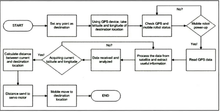
1.6 Summary of Methodology
The methodology of this project is made to achieve the objectives of this project and
also to ensure it not failed the project scope.
START
Calculate ds:ance be:weenOJfTeot
and deSlinatlon
.location
Uslilg GPS dlMce, take latitude and longirude ol
~loc3:ion
ENO
PJOcess the da:.a from
sa!elite """ e.x:rnct
[image:20.514.87.463.220.411.2]useful nbmatiM
Figure 1: Workflow of this project
No?
Read GPS da!a
For starting, set any point as the destination location. Then, by using GPS
device, take latitude and longitude of the destination location. Next, check the GPS and
mobile status, and then power-up the mobile robot. When mobile robot ON, it
automatically start read data GPS from satellite and process the data and extract useful
information. It needs about 45second to lock its coordinate. Afte!" that, the data send to
main board of robot and being analyze. After analyze process finish, the current
coordinate obtain. Then, by using Haversine formula, its calculate distance between two
points (the destination fix by the user) send the output as input to motor and lastly the
mobile robot will move to the new location.
©Universiti Teknikal Malaysia Melaka
5
1. 7 Report structure
This report consists of five chapters which are Chapter I: Introduction, Chapter 2:
Literature Review, Chapter 3: Methodology, Chapter 4: Result, and Chapter 5:
Conclusion
In chapter I is Introduction, discussed about the project background, objectives,
problem statement, scope of project, importance of this project and also summary of
methodology. Chapter 2 is Literature review which is review the previous project and
also all material theory and mathematical theory use in this project. Chapter 3 is all
about methodology where flows process of project, the hardware and software use in
this project. Chapter 4 which is discusses about the result gain from this project and also
future works. Lastly, Chapter 5 is about the conclusion after completing this project and
also recommendation (future works).
6
CHAPTER2
LITERATURE REVIEW
2.1 Previous Relate Works
GPS technology now becomes more popular among human in case they lost or
searching for something around the world. Three young student from China do some
research how to match GPS track with the road in the electronic map accurately [4]
using algorithm. Map matching algorithm have two processes which is firstly find the
road which the car running on it and second make the GPS points projection on the
road which car running on it. It finds a link in the road layer in the electronic map, this
link includes the nearest point to GPS point, it calculates' to this point with perpendicular algorithm. They found that there has no problem and error matching
problem in the whole running process and if there happened some error matching about
the 30 parking lots and highways, the algorithm can find and adjust error immediately
Other project using GPS is research by 4 students from UiTM Shah Alam [6]
which is aim to GPS to locate the position of user. They also calculate the distance
©Universiti Teknikal Malaysia Melaka
7
between 2 points on earth using Haversine formula. In their research also, the
performance of GPS receiver been analyzed at certain location such as at open space
and at forest. They found that, the environment can affect the signal from satellite to
GPS receiver. U.S. Patent No. 5,225,842 by Brown, Alison K., and Mark A. Sturza
with title Vehicle tracking system employing global positioning system (GPS)
satellites is discuss about navigation system for tracking vehicle or other object on or
near the earth surface using GPS [7]. From their research, they have claimed 32 facts from their research, for example a tracking system employing global positioning system satellites for determining the position of 1 or more object to be tracked, the
tracking system comprising; sensor and workstation. U.S. Patent No. 6,392,591 by
William Hsu, Oliver Huang, Vincent Hung and Neil Yang with Global positioning
system discuss relates to global positioning system with miniature size, reduced cost and low electrical current consumption[8]. They have claimed 3 facts which is a GPS for connecting to the external communication and processing unit comprising a receiving unit amplifying, a satellites positioning ASIC, a serial-parallel data bus and a digital interface circuit. They also claim wherein the digital interface circuit is a field
programmable gate array (FPGA), an 8051 chip or a USB controller. The last they
claimed is wherein the raw receiver position data is receives by the PC, mobile phone or PDA connected to a second terminus of the serial-parallel data bus.
2.2 Introduction of Global Positioning System
Global Positioning System (GPS) is a satellite-based navigation system that was
developed by the U.S. Department of Defense (DoD) in the early 1970s, originally run
with 24 satellites and it became fully operational in 1994 [l]. However, it was later
made available to civilians, and is now a dual-use system that can be accessed by both
military and civilian users. In definition, global positioning system (GPS) defined as a
process used to establish a position at any point on the globe and provide specially
coded satellite signals that can be processed in a GPS receiver, enabling the receiver to
compute position, velocity and time, anywhere in the world under any weather
conditions
8
2.2.1 GPS Segment
];-~~~, ~·;··
[image:24.514.94.434.66.336.2]Master Station Control Stations Ground Antenna
Figure 2: GPS Segment
GPS consists of three segments: the space segment, the control segment, and the user
segment [3]. The space segment consists of the 24-satellite, each satellite is in orbit
above the earth at an altitude of 11,000 nautical miles (12,660 miles), and takes 12
hours to orbit one time. There are 6 orbital planes each having 4 satellites. The orbits
are tilted to the equator of the earth by 55° so that there is coverage of the Polar
Regions. The satellites continuously orient themselves to ensure that their solar panels
stay pointed towards the sun, and their antennas point toward the earth. GPS satellite
transmits a signal, which is, two sine waves (also known as carrier frequencies), two
digital codes, and a navigation message. The codes and the navigation message are
added to the carriers as binary biphase modulations. The carriers and the codes are used
mainly to determine the distance from the user receiver to the GPS satellites. The
navigation message contains, along with other information, the coordinates (the
location) of the satellites as a function of time.
The control segment of the GPS system consists of a 5 worldwide network of tracking
stations, with a master control station (MCS) located in the United States at Colorado
Springs, Colorado. The primary task of the operational control segment is tracking the
©Universiti Teknikal Malaysia Melaka