Transactions Letters
Coherent and Differential Downlink Space-Time Steering Aided
Generalised Multicarrier DS-CDMA
Mohammed El-Hajjar,
Graduate Student Member, IEEE,
Bin Hu, Lie-Liang Yang,
Senior Member, IEEE
,
and Lajos Hanzo,
Fellow, IEEE
Abstract— This paper presents a generalised MultiCarrier Direct Sequence Code Division Multiple Access (MC DS-CDMA) system invoking smart antennas for improving the achievable performance in the downlink. In this contribution, the MC DS-CDMA transmitter employs an Antenna Array (AA) and Steered Space-Time Spreading (SSTS). Furthermore, the proposed sys-tem employs both Time and Frequency (TF) domain spreading for extending the capacity of the system, which is combined with a user-grouping technique for reducing the effects of Multi-User Interference (MUI). Moreover, to eliminate the high-complexity Multiple Input Multiple Output (MIMO) channel estimation required for coherent detection, we also propose a Differential SSTS (DSSTS) scheme. More explicitly, for coherent SSTS detectionMV Nr number of channel estimates have to be generated, where M is the number of transmit AAs, V is the number of subcarriers andNris the number of receive antennas. This is a challenging task, which renders the low-complexity DSSTS scheme attractive.
Index Terms— MIMO, MC DS-CDMA, beamforming, space-time spreading, differential space-space-time spreading.
I. INTRODUCTION
T
HE fundamental limitations of reliable wireless trans-missions are imposed by time-varying multi-path fading, which has to be counteracted by sophisticated transceiver de-sign [1]. In [2], Alamouti proposed a simple transmit diversity scheme employing a Space-Time Block Code (STBC) [3], which was capable of achieving a substantial diversity gain by simultaneously transmitting two symbols with the aid of two antennas. Inspired by the philosophy of STBC, Hochwaldet al. [4] proposed the transmit diversity concept known as Space-Time Spreading (STS) for the downlink of Wide-band Code Division Multiple Access (WCDMA) [5] and demonstrated that STS is capable of achieving the highest possible transmit diversity gain. Furthermore, in recent years, numerous research contributions have appeared on the topic of
Manuscript received November 11, 2005; revised January 26, 2007 and August 14, 2007; accepted August 20, 2007. The associate editor coordinating the review of this paper and approving it for publication was A. Yener. The financial support of Vodafone under the auspices of the Dorothy Hodgkin Postgraduate Award as well as that of the European Union under the auspices of the Pheonix and Newcom projects is gratefully acknowledged.
M. El-Hajjar, L.-L. Yang, and L. Hanzo are with the School of Electrical and Computer Science, Univ. of Southampton, United Kingdom (e-mail: {meh05r, lly, lh}@ecs.soton.ac.uk).
B. Hu is with NIST, USA (e-mail: [email protected]). Digital Object Identifier 10.1109/TWC.2007.05807.
MultiCarrier Direct Sequence Code Division Multiple Access (MC DS-CDMA), which constitutes an attractive scheme [5– 8] based on a combination of DS-CDMA and Orthogonal Frequency Division Multiplexing (OFDM). In [9, 10] a gener-alised MC DS-CDMA scheme was proposed that includes the subclasses of both multi-tone and orthogonal MC DS-CDMA as special cases. On the other hand, beamforming [11, 12] constitutes an effective technique of reducing the Multiple-Access Interference (MAI), where the antenna gain is in-creased in the direction of the desired user, whilst reducing the gain towards the interfering users. In [13] a hybrid downlink technique designed for achieving both transmit diversity and transmit beamforming was proposed for Direct Sequence Code Division Multiple Access (DS-CDMA), which is referred to as Steered Space-Time Spreading (SSTS).
However, the schemes of [2, 4, 13] are based on the assump-tion that perfect Channel State Informaassump-tion (CSI) is available at the receiver. The estimation accuracy of the CSI has a grave impact on the attainable detection performance. Naturally, the estimation of these parameters increases the complexity imposed and typically requires substantial channel sounding overhead, which wastes valuable bandwidth. By contrast, Differential Space-Time Modulation (DSTM) schemes [14, 15], introduced as extensions of the traditional differential phase shift keying scheme, were shown to be capable of reliable data detection without any CSI, which is a partic-ularly attractive feature in rapidly fading channels. Hence, DSTM schemes obviate the need for channel estimation at the receiver, while retaining the desirable benefits of space-time coding techniques. However, the performance of DSTM systems significantly degrades in the presence of even rela-tively mild Interference and breaks down completely, when strong interference is inflicted [16]. To suppress the effects of co-channel interference, a Differential Space-Code Modulation (DSCM) scheme was proposed by combining the merits of the DSTM and spread spectrum techniques in [16].
In this paper, we amalgamate the merits of SSTS and gen-eralised MC DS-CDMA to enhance the system’s performance by achieving both spatial diversity and beamforming gain. We demonstrate that the number of users supported is substantially increased by spreading in both the Time and Frequency (TF) domain. Additionally, we propose a user-grouping technique
Serial−to−Parallel
Conveter
STS
. . .,
.
.
.
...
...
Beamformer
.
.
.
Users’ DOA
...
Beamformer
.
.
.
Data
. . .,
. . .,
.
.
.
Users’ DOA bk,2Nl
bk,21,
× ×
cos(2πf11t+φk,11)
×
×
× ×
cos(2πf12t+φk,12)
cos(2πf1Vt+φk,1V)
1
2
V
UV
sk,1(t)
W11
W12
W1L
Antenna Array 1
1
2
L
...
×
×
×
× × ×
Tb
bk,11,
Symbol DurationTs=U Tb
bk,1Nl
bk,UNl bk,U1,
cos(2πf12t+φk,12)
cos(2πf1Vt+φk,1V)
1
2
V
UV
1
2
L
...
cos(2πf11t+φk,11)
sk,M(t)
WM1
WM2
WML
[image:2.567.105.469.53.318.2]Antenna Array M
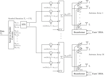
Fig. 1. Thekth user’s transmitter schematic for the downlink of the SSTS assisted generalised Multicarrier DS-CDMA system.
that is used for minimising the Multi-User Interference (MUI) imposed, when employing TF-domain spreading in the SSTS-aided generalised MC DS-CDMA downlink. We also propose a Differential SSTS (DSSTS) scheme by amalgamating the benefits of the differential space-time scheme of [14] with those of smart antenna aided generalised MC DS-CDMA sys-tems for the sake of eliminating the high-complexity Multiple Input Multiple Output (MIMO) channel estimation required for coherent detection at the expense of a3dB loss in perfor-mance, when compared to a coherent system assuming perfect CSI recovery at the receiver. More quantitatively, the DSSTS scheme dispenses with the estimation of theM V Nr antenna links required by the coherently detected SSTS scheme, where
M is the number of half-wavelength-spaced beamforming clusters,V is the number of subcarriers andNris the number of receive antennas.
The rest of this paper is organised as follows. In Section II the philosophy of the downlink SSTS-aided generalised Mul-ticarrier DS-CDMA system is described and characterised. Then, Section III introduces the differentially encoded SSTS scheme followed by Section IV that considers the performance improvements of generalised MC DS-CDMA using SSTS and TF-domain spreading. In Section V a user grouping technique that reduces the effects of multi-user interference on the performance of the proposed systems is presented. Finally, the attainable performance of these schemes is studied comparatively in Section VI, followed by our conclusions in Section VII.
II. STEERED-SPACETIMESPREADING
In [13] a hybrid technique designed for achieving both transmit diversity and beamforming referred to as SSTS was presented. The antenna architecture employed in Figure 1 for the SSTS scheme of [13] has two AAs spaced sufficiently far
apart in order to achieve second-order transmit diversity. The
Lnumber of elements of each of the two AAs are spaced at a distance of d=λ/2 for the sake of achieving beamforming. In [13] the SSTS scheme has been investigated in the context of DS-CDMA. By contrast, in this contribution we extend our study to the generalised MC DS-CDMA system. When we haveL= 1, no beamforming is activated and hence the stand-alone Space-Time Spreading (STS) transmit diversity scheme is employed. Otherwise, the more general SSTS scheme is invoked and hence the STS scheme may be viewed as a special case of the generic SSTS arrangement in conjunction with
L= 1.
A. Transmitter Model
The system considered in this section is an evolutionary descendent of the generalised MC DS-CDMA scheme of [9] using U V number of subcarriers. The transmitter schematic of thekth user is shown in Figure 1, where a block of U M
thevth subcarrier of thekth user, which is generated for the
mth array.
The general form of thekth user’s transmitted signal can be expressed as
sk(t) =sk(τ+nM Ts)
=
U
u=1
V
v=1
2Pk
V L
1
M MW
k
vBkuCkcos(2πfuvτ+φk,uv),
(1)
where 0 ≤ τ < M Ts, n = 0,1, . . ., Pk/V represents the transmitted power of each subcarrier, the factor L in the denominator is due to beamforming and the factorM Min the denominator suggests that the STS scheme usingM transmit antennas and M orthogonal spreading codes distributes its power proportionally in space and time. Additionally, φk,uv
represents the phase angle introduced in the carrier modulation process of user k in the uvth subcarrier and is uniformly distributed over[0,2π], while the SSTS array weight matrix
W(k)and the spreading sequence matrixCk can be expressed
as
Wvk =
⎡ ⎢ ⎢ ⎢ ⎣
(wkv,0)∗ 0 . . . 0 0 (wkv,1)∗ . . . 0
..
. ... . .. ...
0 0 . . . (wv,Mk −1)∗ ⎤ ⎥ ⎥ ⎥ ⎦ and
Ck =
⎡ ⎢ ⎢ ⎢ ⎣
ck,1[0] . . . ck,1[M Ne−1] ck,2[0] . . . ck,2[M Ne−1]
..
. . .. ...
ck,Nl[0] . . . ck,Nl[M Ne−1]
⎤ ⎥ ⎥ ⎥
⎦, (2)
where0= [0,0, . . . ,0]T is anL-dimensional vector,wkv,mis theL-dimensional weight vector for themth beamformer AA and thevth subcarrier of thekth user.
ForM = 2, the matrixBkucan be expressed as [4]
Bk,u=
bk,u1 bk,u2 bk,u2 −bk,u1
. (3)
B. Receiver Model
In the following we consider the case of a single re-ceive antenna, although its extension to multiple rere-ceive antennas is straightforward. The L-dimensional Spatial-Temporal (ST) Channel Impulse Response (CIR) vector be-tween the uvth subcarrier of the kth user and the mth AA can be expressed as h(uv,mk) (t) = auv,m(k) (t)δ(t−τk) =
auv,m(k) 0(t), . . . , auv,m(k) (L−1)(t)
T
δ(t−τk), where τk is the signal’s delay,a(uv,mlk) (t) is the CIR with respect to theuvth subcarrier of thekth user and thelth element of themth AA. Based on the assumption that the array elements are separated by half a wavelength, we have
auv,m(k) (t) =αuv,m(k) (t)d(k), (4)
where α(uv,mk) (t) is a Rayleigh faded envelope, d(k) = [1,exp(j[πsin(ψ(k))]), . . . ,exp(j[(L−1)πsin(ψ(k))])]T and
ψ(k) is the kth user’s Direction of Arrival (DOA).
Assuming that theKusers’ signals expressed in the form of (1) are transmitted synchronously over the downlink Rayleigh
fading channels, the baseband data matrix Yu,n ∈ CV×NlNe
received by user1 overV number of subcarriers after multi-carrier demodulation can be expressed as
Yu,n=Hu K
k=1
2Pk V L
1
M MW
kB
ku,nCk+Nn, (5)
whereNn ∈ CV×NlNe denotes the Additive White Gaussian
Noise (AWGN) matrix. In (5), the unknown fading matrixHu
can be expressed as
Hu=
⎡ ⎢ ⎢ ⎢ ⎢ ⎢ ⎣
(h(1)u1,0(t))T . . . (h(1)u1,(M−1)(t))T (h(1)u2,0(t))T . . . (h(1)u2,(M−1)(t))T
..
. . .. ... (h(1)uV,0(t))T . . . (h(1)uV,(M−1)(t))T
⎤ ⎥ ⎥ ⎥ ⎥ ⎥ ⎦
. (6)
Based on the orthogonality of the spreading codes, we multiply both sides of (5) with the spreading code ma-trix C1 of the desired user and hence attain Zu,n =
2P1
V LMM1 HuW1B1u,n+NnC†1. In this scenario, the MRC
criterion based transmit beamformer, which constitutes an effective solution to maximising the antenna gain in the direction of the desired user, namely user 1 in this case, is the optimum beamformer. Let wmk = d(k) in (4), then the term Zu,n can be expressed as
Zu,n=
2P1 V L
1
M MH˜uB1u,n+NnC
†
1, (7)
where the superscript†denotes the conjugate transpose oper-ation and the (V ×M)-dimensional matrixH˜u is given by
˜
Hu=L×
⎡ ⎢ ⎢ ⎢ ⎢ ⎢ ⎣
α(1)u1,0 . . . α(1)u1,(M−1) α(1)u2,0 . . . α(1)u2,(M−1)
..
. . .. ...
α(1)uV,0 . . . α(1)uV,(M−1)
⎤ ⎥ ⎥ ⎥ ⎥ ⎥ ⎦
. (8)
Note that the case of L = 1 corresponds to the stand-alone STS scheme, where wkm = 1. Hence, no information is required about the users’ DOA. Finally, by invoking the STS receiver of [4], the received signal can be decoded.
III. DIFFERENTIALSTEEREDSPACE-TIMESPREADING
A. Differential Space-Time Modulation
Before commencing our investigation of the DSSTS schemes, we provide a brief introduction to the unitary group code based DSTM of [14]. Let Xn be an (M × Nl) -dimensional space-time code to be transmitted byM antennas overNl time samples, whereNlis the time-domain length of the space-time code. For differential space-time coding we have [14]
XnX†n=NlIM, Xn =Xn−1Gn, X0=D, ∀n, (9)
whereIM is an (M ×M)-dimensional identity matrix, Gn
is the matrix representing thenth information bearing unitary group code andDis a known fixed matrix. For example, for
M =Nl= 2, the pair [14] G = {G0,G1,G2,G3}
=
1 0 0 1
,−
1 0 0 1
,
0 1 −1 0
,
0 −1 1 0
,
D =
1 −1 1 1
, (10)
is a unitary group code designed over the BPSK constel-lation {1,−1} and Gn ∈ G. Each information bit pair in
{00,01,10,11}corresponds to an element inG. The mapping Mmaps two consecutive bits ontoG by assigningM(00) = G0,M(01) =G1,M(10) =G2 andM(11) =G3.
The matrix Yn ∈ CNr×Nl of received data at the out-put of the Nr receive antennas has the form of Yn =
P
MHXn+Nn, where H ∈ CNr×M denotes the unknown
matrix of complex-valued non-dispersive fading coefficients in a flat fading environment, Nn ∈ CNr×Nl denotes the AWGN matrix and P/M represents the power transmitted from each antenna [14]. Each of the elements ofH andNn is assumed to be an independently and identically distributed (i.i.d.) complex Gaussian random variable with zero-mean and unit variance. Then, the low-complexity differential receiver dispensing with channel estimation has the form of Gˆn =
arg max
Gn∈G
ReTrGnYn†Yn−1, where ”ReTr” denotes the real
part of the trace of a matrix [14].
B. System Model
According to Figure 1, a block ofU M data bits each having a bit duration ofTb is Serial-Parallel converted toU parallel sub-blocks. By using the mappingGdescribed in Section III-A, the transmitter maps theM bits of each sub-stream to the information matrix Gku,n. Then we attain the nth M ×Nl
space-time code Xku,n = Xku,n−1Gku,n. After spreading
Xku,nwith the aid ofNlorthogonal Walsh-Hadamard
spread-ing codes {ck,1, ck,2, . . . , ck,M}, k = 1,2, . . . , K, by the DSSTS scheme of Figure 1, theU M outputs of theU number of DSTS blocks are multicarrier-modulated to a group of subcarrier frequencies {fu1, fu2, . . . , fuV}, which are then forwarded to the M arrays of the transmitter. The symbol duration of the DSTS signals isM Ts, and the length of the orthogonal codes isM Ts/Tc=M Ne, whereNe=Ts/Tcand
Tc represents the chip-duration of the orthogonal spreading codes. Finally, according to thekth user’s Direction of Arrival (DOA), theU M V signals of thekth user are weighted by the
transmit weight vectorw(v,mk) determined for thevth subcarrier of the kth user, which is generated for the mth array, m =
1, . . . , M. It is reasonable to assume that at moderate mobile speeds the users’ DOAs change slowly and hence may be estimated correctly.
The general form of the kth user’s transmitted signal can be expressed as in Equation (1) by replacing Bku,n with
Xku,n. The signal is transmitted through the same channel model as that described in Section II-B and then multicarrier-demodulated to arrive at the following received signal for user 1:
Zu,n=
2P1 V L
1
M MH˜uX1u,n+NnC
†
1. (11)
By invoking the differential receiver of [14], we arrive at the matrix
ˆ
Gku,n=arg max Gku,n∈G
ReTrGku,nZ†u,nZu,n−1. (12)
IV. PERFORMANCEIMPROVEMENTUSING TIME-FREQUENCY-DOMAIN SPREADING
As proposed for MC-CDMA schemes in [5, 17], spreading in the F-domain may additionally be employed for the sake of increasing the diversity gain by exploiting the independent fading of the subcarriers in the F-domain. Hence in the generalised MC DS-CDMA scheme advocated, the transmitted data stream can be spread in both the T-domain and the F-domain in order to support more users, while achieving a higher frequency diversity gain [10] by exploiting the independence of the time and frequency-domain fading. As a further benefit, the complexity of implementing separate T- and F-domain Multi-User Detectors (MUD) for short spreading codes is expected to be significantly lower than that of a single T-domain MUD designed for long codes. The resultant bandwidth is the same as that of the MC DS-CDMA scheme employing time-domain-only spreading, while the total number of users supported becomesVKmax=V Ne, which is V times the number of users supported by the MC DS-CDMA scheme employing time-domain-only spreading. Let ck = {ck[0], ck[1], . . . , ck[V −1]} be the kth user’s
orthogonal F-domain spreading code. Following the approach of Section II, the received baseband data matrixYu,n can be
modified from (5) to
Yu,n= K
k=1
2Pk V L
1
M MC
kHuWkBku,nCk+Nn, (13)
where the (V ×V)-dimensional F-domain spreading code matrix has the diagonal structure ofCk=diag{ck}.
By multiplying both sides of (13) with the conjugate trans-pose of the T-domain spreading code matrix C1 defined in Equation (2) as well as with the F-domain spreading code matrix C1 of the desired user, namely with that of user 1,
and letting wkm=d(k), we have
Zu,n =
2P1
V L
1
M MH˜uB1u,n+C
†
1NnC†1
+
K
k=2
2Pk V L
1
M MC
†
1Ckd(1)d(k)†HuBku,n,
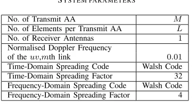
TABLE I SYSTEM PARAMETERS
No. of Transmit AA M
No. of Elements per Transmit AA L
No. of Receiver Antennas 1
Normalised Doppler Frequency
of theuv,mth link 0.01 Time-Domain Spreading Code Walsh Code Time-Domain Spreading Factor 32 Frequency-Domain Spreading Code Walsh Code Frequency-Domain Spreading Factor 4
whereK is the number of users sharing the same T-domain spreading code matrix with the desired user, where these otherwise inseparable users are differentiated by their unique F-domain codes. Finally, the term
K k=2
2Pk
V LMM1 C†1Ckd(1)d(k)†HuBku,n in Equation (14) represents the MUI.
We know from Equation (14) that MUI is inevitably im-posed, since the orthogonality of the F-domain spreading codes cannot be retained over frequency-selective fading chan-nels. However, the desired signal is not interfered by the transmitted signals of the users employing different orthog-onal T-domain spreading codes, provided that synchronous downlink transmission of all the KKmax user signals as well as flat-fading of each subcarrier are assumed. Only the users sharing their T-domain spreading code matrix with the desired user will impose MUI on the desired user. Therefore, the MUI can be reduced, if we carefully select the (K−1) potentially interfering users, namely those which have the lowest F-domain interference coefficient with respect to the desired user, from the entire set of all the KKmax users. More explicitly, when selecting the specific users for the sake of sharing the same T-domain spreading code with the desired user, it must be ensured that their TF-domain interference remains low and hence they remain distinguishable. The user grouping technique will be discussed in the following section.
V. USERGROUPINGTECHNIQUE
As mentioned in the previous section, the MUI is inevitably imposed. However, the MUI can be reduced, if the (K−1) users are carefully selected, so that the specific-users having the lowest F-domain interference coefficient with respect to the desired user share the same T-domain spreading code with the desired user, who are carefully selected from the entire set of all theKKmax users. In the spirit of [18] other low-complexity grouping techniques, the proposed user grouping algorithm is suboptimal, yet its performance improvements justify its employment as we will show in Section VI.
The above-mentioned interference coefficient can be defined asρ1k =d(1)d(k)†, which can be evaluated before transmis-sion ensues, based on the assumption that the users’ DOAs are perfectly estimated. In the absence of any prior knowledge, the initial value of ρth is set to 0. The users having an F-domain interference coefficient of ρk1k2 < ρth are deemed to be the users interfering with each other. Furthermore, when thek1th user shares the same T-domain spreading code with the k2th user, they belong to the same time domain group and are differentiated by their F-domain spreading
0 2 4 6 8 10 12 14 16 18 20
Eb/N0[dB]
10-6 10-5 10-4 10-3 10-2 10-1 1
BER
1 user 32 users 64 users
(4 1) (2 2)
(2 2), users grouping
Fig. 2. BER performance of the SSTS-aided generalised MC DS-CDMA DL using a (4×1)-dimensional AA (M= 4,L= 1) and a (2×2)-dimensional AA (M = 2,L= 2) in conjunction with a varying number of users and the system parameters outlined in Table I. In this result TF-domain spreading and user grouping were employed to improve the system performance while supressing the MUI.
codes. The algorithm aims for ensuing that the users sharing the same T-domain sequence have the lowest possible F-domain interference coefficient. The selection procedure will continue, until all the users have been grouped. However, if the threshold value ρth was set too low, some users cannot be allocated to any of the T-domain user groups owing to imposing an F-domain interference coefficient lower thanρth. In this scenario, ρth is increased by a given step size of 0 < μ < L. Based on the increased threshold value, another user allocation attempt is initiated. The process continues until all the users are grouped. Following this user-grouping procedure, the effect of the interfering signals imposed on the desired user’s signal becomes less pronounced. Therefore, the achievable BER performance is improved.
VI. PERFORMANCERESULTS
In this section, we consider the downlink (DL) of a gen-eralised MC DS-CDMA system employing an (M × L )-dimensional transmit AA and a single receive antenna, while using both coherent SSTS and DSSTS in order to demonstrate the performance improvements achieved by the proposed system both in the presence and absence of channel estimation. Furthermore, the results for the coherent SSTS scheme are all done for the case of perfect channel knowledge at the receiver. All simulation parameters are listed in Table I. More explicitly, for coherent SSTS detection M V Nr number of channel estimates have to be generated, where Nr is the number of receive antennas. This is a challenging task which renders the low-complexity DSSTS scheme attractive.
In Figure 2 we plot the BER performance versus theEb/N0
of the SSTS-aided generalised MC DS-CDMA DL scheme using both a (4×1)-dimensional AA (M = 4,L = 1) and a (2 ×2)-dimensional AA (M = 2, L = 2) for K = 1, 32 and 64 users, where Eb denotes the energy per bit and
N0 denotes the double sided noise power spectral density. The remaining system parameters are outlined in Table I. Figure 2 shows that the performance of the system supporting
[image:5.567.58.247.68.170.2]0 2 4 6 8 10 12
Eb/N0[dB]
10-6 10-5 10-4 10-3 10-2 10-1 1
BER
[image:6.567.41.246.53.212.2](2 1) (2 2) (2 3) (2 4)
Fig. 3. BER performance of the SSTS-aided generalised MC DS-CDMA DL usingM = 2antennas arrays and a variable number of elements per antenna in conjunction with one user and the system parameters outlined in Table I.
user, since no interference is encountered by the K = 32
users employing different orthogonal32-chip Walsh codes as their T-domain DS spreading in the synchronous DL. Let us now consider TF-domain spreading, which is employed for the sake of supporting K = 64 users. Consequently, MUI is inevitably introduced among the users sharing the same T-domain spreading code. This becomes clear in Figure 2 for the case ofK= 64users when no user grouping was employed, since the performance of the SSTS system supportingK= 64
users is significantly worse than that supporting a single user or even K = 32 users. However, when user grouping is employed by the SSTS system for the sake of reducing the MUI imposed, the performance of the SSTS system supporting
K = 64 users substantially improves. Consequently, as a benefit of the user grouping technique, the BER performance of the64-user system is only slightly inferior in comparison to that serving a single user.
Furthermore, Figure 3 shows the effect of increasing the beamforming gain by increasing the number of beam-steering elements L in the AA. As shown in the figure, when the number of beam-steering elements increases, the achievable BER performance substantially improves. This trend appears more beneficial in comparison to the system employing only spatial diversity as in the space-time block codes of [3], where most of the diversity gain is achieved while employing two transmit antennas, since upon increasing the number of transmit antennas further, the additional transmit diversity gain tends to remain modest. This phenomenon will be further explained in Figure 5.
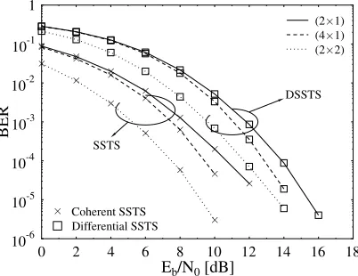
In Figure 4, K = 4 users are supported. Observe in Figure 4 that as expected, the attainable performance of the low-complexity DSSTS schemes dispensing with channel estimation is about3dB worse than that of the SSTS schemes assuming perfect channel knowledge and in practice requiring the estimation ofM V Nr= 8channels for coherent detection. The DSTS system using a(4×1)-dimensional AA achieved a slightly better performance than the DSTS system using a (2 × 1)-dimensional AA, since the highest incremental diversity gains are achieved upon increasing the number of antennas from one to two, i.e. by100%, while adding further
0 2 4 6 8 10 12 14 16 18
Eb/N0[dB]
10-6 10-5 10-4 10-3 10-2 10-1 1
BER
Coherent SSTS Differential SSTS
(2 1) (4 1) (2 2) DSSTS
SSTS
Fig. 4. BER performance of the SSTS- and DSSTS-aided generalised MC DS-CDMA DL using a (2×1)-dimensional AA (M= 2,L= 1), a (4×1 )-dimensional AA (M= 4,L= 1) and a (2×2)-dimensional AA (M = 2,
L= 2) fork= 4users and the system parameters outlined in Table I.
additional antennas achieves modest extra diversity gains on the downlink. Furthermore, Figure 4 shows that the DSSTS system employing a(2×2)-dimensional AA outperforms the DSTS system using a(4×1)-dimensional AA, suggesting that the DSSTS scheme employs DSTS to obtain transmit diversity, but additionally invokes beamforming to attain a higher SNR gain.
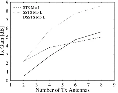
Finally, the SNR gain achieved over a (1×1)-dimensional AA bench-marker upon increasing the total number of an-tennas at a fixed BER of 10−5 was portrayed in Figure 5, whereK = 32users were supported in conjunction with the system parameters outlined in Table I. The figure shows the attainable SNR gains for different systems, namely for STS employing an (M×1)-dimensional AA forM = 2,4,6, and 8, as well as for both SSTS and DSSTS employing (M×L )-dimensional AAs in conjunction with M = 2 and L = 1, 2, 3, and 4. As expected, the attainable SNR gain increased as the total number of antennas was increased. However, as mentioned in the context of Figure 3, the SNR gain of SSTS owing to beamforming remains superior to that of the STS scheme designed for pure transmit diversity. This is shown explicitly in Figure 5, where the slope of the SNR gain of each system shows that the highest relative SNR gain is achieved for the STS system, when employing two transmit diversity antennas. As the number of transmit antennas is increased further, the resultant additional SNR gain becomes more modest. However, the SNR gain increases substantially for both SSTS and DSSTS, as the number of antennas increases, which is the joint benefit of achieving both spatial diversity gain as well as beamforming gain.
VII. CONCLUSIONS
[image:6.567.304.505.56.211.2]1 2 3 4 5 6 7 8 9
Number of Tx Antennas
0 1 2 3 4 5 6 7 8 9
Tx
Gain
[dB]
STS M 1 SSTS M L DSSTS M L
Fig. 5. Transmit gain versus the number of transmit antennas for the various schemes invoked in this paper at a BER of10−5while employing the system parameters outlined in Table I.
compared to conventional systems employing a single element per AA. Explicitly, observe in Figure 5 that the system employing a (2×4)-dimensional AA for second order transmit diversity and fourth order beamforming attains an antenna gain of3.5 dB over the system using an (8×1)-dimensional AA for eighth order transmit diversity but dispensing with beamforming. The number of users supported was increased from K = 32 to K = 64 without substantially degrading the achievable BER in Figure 2, when combining TF-domain spreading with the proposed user grouping technique for reducing the effect of the MUI on the system’s performance. Finally, the system’s complexity was substantially reduced by eliminating theM V Nr MIMO links’ estimation required for coherent detection by employing non-coherently detected DSSTS at the cost of an approximately 3 dB performance degradation.
REFERENCES
[1] L. Hanzo, T. H. Liew, and B. L. Yeap,Turbo Coding, Turbo Equalisation and Space Time Coding: For Transmission over Fading Channels. Chichester, UK: John Wiley and Sons Ltd. and IEEE Press, NY, USA, 2002.
[2] S. Alamouti, “A simple transmit diversity technique for wireless commu-nications,”IEEE J. Sel. Areas Commun., vol. 16, no. 8, pp. 1451–1458, 1998.
[3] V. Tarokh, H. Jafarkhani, and A. Calderbank, “Space-time block codes from orthogonal designs,” IEEE Trans. Inf. Theory, vol. 45, no. 5, pp. 1456–1467, 1999.
[4] B. Hochwald, T. Marzetta, and C. Papadias, “A transmitter diversity scheme for wideband CDMA systems based on space-time spreading,” IEEE J. Sel. Areas Commun., vol. 19, no. 1, pp. 48–60, 2001. [5] L. Hanzo, L.-L. Yang, E.-L. Kuan, and K. Yen,Single and Multi-Carrier
DS-CDMA: Multi-user Detection, Space-Time Spreading, Synchronisa-tion, Networking and Standards. Chichester, England: John Wiley and Sons Ltd. and IEEE Press, NY, USA, 2003.
[6] L. Hanzo, M. Muenster, B. Choi, and T. Keller,OFDM and MC-CDMA for Broadband Multi-User Communications, WLANs and Broadcasting. Chichester, UK: Wiley, 2003.
[7] E. A. Sourour and M. Nakagawa, “Performance of orthogonal multi-carrier CDMA in a multipath fading channel,”IEEE Trans. Commun., vol. 44, pp. 356–367, March 1996.
[8] L. Vandendorpe, “Multitone spread spectrum multiple access communi-cations system in a multipath Rician fading channel,”IEEE Trans. Veh. Technol., vol. 44, pp. 327–337, May 1995.
[9] L.-L. Yang and L. Hanzo, “Performance of generalized multicarrier DS-CDMA over Nakagami-m fading channels,”IEEE Trans. Commun., vol. 50, pp. 956–966, June 2002.
[10] L.-L. Yang and L. Hanzo, “Performance of broadband multicarrier DS-CDMA using space-time spreading-assisted transmit diversity,”IEEE Trans. Wireless Commun., vol. 4, no. 3, pp. 885–894, 2005.
[11] J. Blogh and L. Hanzo, Third-Generation Systems and Intelligent Wireless Networking: Smart Antennas and Adaptive Modulation. John Wiley and Sons Ltd. and IEEE Press, NY, USA, 2002.
[12] Y. Liang and F. Chin, “Transmit antenna array techniques for cellular WCDMA systems,” inProc. IEEE 9th PIMRC, pp. 1396–1400, Sept. 1998.
[13] R. A. Soni, R. M. Buehrer, and R. D. Benning, “Intelligent antenna system for CDMA2000,”IEEE Signal Processing Mag., vol. 19, pp. 54– 67, July 2002.
[14] B. L. Hughes, “Differential space-time modulation,”IEEE Trans. Inf. Theory, vol. 46, pp. 2567–2578, Nov. 2000.
[15] B. Hochwald and W. Sweldens, “Differential unitary space-time modu-lation,”IEEE Trans. Commun., vol. 48, no. 12, pp. 2041–2052, 2000. [16] J. Liu, J. Li, H. Li, and E. Larsson, “Differential space-code modulation
for interference suppression,”IEEE Trans. Signal Processing, vol. 49, no. 8, pp. 1786–1795, 2001.
[17] S. Hara and R. Prasad, “Overview of multicarrier CDMA,” IEEE Commun. Mag., vol. 35, pp. 126–133, Dec. 1997.
[image:7.567.47.246.55.211.2]