1
Solid State MPD Thruster with Applied Magnetic Field
IEPC-2007-158
Presented at the 30th International Electric Propulsion Conference, Florence, Italy September 17-20, 2007
M. Coletti*
University of Southampton, Southampton, SO17 1DR, United Kingdom
A. Balestra† and M. Sensini‡
University of Rome “La Sapienza”, Rome, 00185,Italy
And
G. Paccani§
University of Rome “La Sapienza”, Rome, 00185, Italy
A solid state MPD thruster with applied magnetic field has been investigated. The MPD has been operated with applied fields up to 0.4 T. Current, impulse bit and ablated mass have been measured. The thruster has shown a threshold value of the applied magnetic field over which it does not work, this threshold value increases with the shot energy. Away from this threshold value the current shows small variation with the applied field. The measured values of the impulse bit are in accordance with the trends shown by previous investigations1 and show a satisfactory agreement with the theoretical values calculated with one of the authors’ theory2.
Nomenclature
A = amplitude of oscillationa = parameter a0 = speed of sound
B = applied magnetic field
Bself = intensity of the self-generated magnetic field
a self
r I B
π μ
2 =
E = shot energy
F = thrust
FB=0 = thrust with no applied magnetic field
I = current
Ib = impulse bit
Im = impulse transferred to the target
k = ratio between the Larmor radius and the characteristic field length kb = Boltzman constant
Mi = ion mass
m = mass
m& = mass flow rate
q = electron charge R = anode over cathode radius ratio Rm = magnetic coil radius
R = radius
Te = electronic temperature
t = time
v = velocity
α = coefficient
ει = ionization energy γ = specific heat ratio
μ = vacuum magnetic permeability
τ = shot duration
ω = angular velocity
ωB = Larmor angular velocity
ξ = current over complete ionization current ratio
Ψ = current parameter Subscript
a = relative to the anode
Ch = calculated using Choueiri’s formula c = relative to the cathode ci = complete ionization
j = relative to the plasma jet with applied field Ti = calculated using Tikhonov’s formula z0 = at the exit section of the thruster
I.
Introduction
HIS paper deals with an experimental analysis of a solid propellant (Teflon) quasi-steady MPD powered by a capacitive PFN with a total capacitance of about 60 mF, a maximum voltage of 450 V and with an instantaneous power of few Megawatts during shots of about one millisecond.
A coaxial thruster with radially-positioned bar-shaped propellant has been investigated while working with and without an applied magnetic field. Current, ablated mass and impulse bit were measured for different values of energy per shot in the 1666÷3000 joule range.
A schematic of the thruster is reported below
T
Anode Magnetic Coils Cathode
[image:2.595.197.404.514.729.2]3
The thruster cathode has a diameter of 18 mm while the anode has a divergent shape with a minimum diameter of 47 mm, a maximum one of 110 mm and a length of 75 mm.
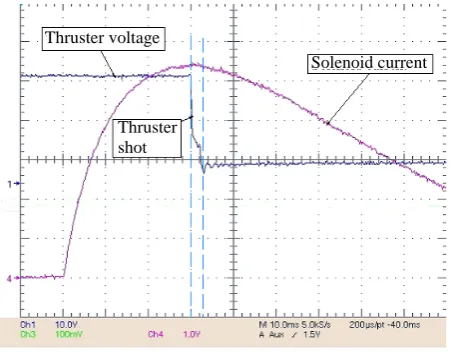
The magnetic field is generated by a solenoid, mounted coaxially to the thruster over the anode to cover the entire discharge region. The magnetic coil is powered by a capacitive PFN, designed to obtain current pulses with a steady state phase lasting for a time much longer than the thruster shot time (Fig. 2) with a maximum magnetic field on the axis of about 0.5 T.
Figure 2. Thruster and solenoid pulse
Due to the presence of such a high applied field a thrust measurement system that is completely free from the field influence is needed. Such a system will be described in next session.
II.
Thrust measuring system
The measurement system that has been used is suitable to small vacuum chamber and is based on the use of a target.
The target that we have used consist in an aluminium cone with a 30° span from the thruster axis and in a series of plastic disks; it is mounted on a translating articulated parallelogram free from constraint (like electric connections with the thruster) and free from any influence due to the applied magnetic field.
The target and the articulated parallelogram are sketched below
[image:3.595.192.418.173.350.2]Figure 3. 3D sketch of the target mounted on the articulated parallelogram
Figure 4. 3D sketch of the target
Solenoid current Thruster voltage
Thruster shot
Proximeter
Plastic discs
Target
Hinges
[image:3.595.70.536.488.674.2]The plasma jet, once ejected from the thruster, enters the target colliding with the aluminium cone. The impinging plume particles, after several collisions, leave the target with a residual momentum that is predominantly radial.
This system is dynamically equivalent to a simple pendulum. The impulse transferred to it by the plasma jet can be calculated from the motion of this system, measured by means of an optoelectronic displacement sensor. Assuming that before the measurement this system is in a state of rest, if it can be represented as a single translating mass m, the impulse is
mv
Im = (1)
being v the mass velocity after the impulse. If the system is represented as a simple pendulum Eq. 1 becomes: A
m
Im = ω (2)
where A is the amplitude of the oscillation and ω its angular frequency.
The imperfect knowledge of the interaction processes between the target and the plasma particles, in particular the degree to which momentum is transferred to the target and the angular reflection processes introduces uncertainty on the measurement.
Depending on the degree of elasticity of the collisions between the particles and the target the momentum transferred to the target can be up to two times bigger than the momentum of the incoming plasma particles.
To take into account this effect an accommodation factor has been introduced.
This factor has been determined comparing the thrust measurement relative to the non-applied field case taken with this target to those done with a “conventional” thrust balance.
The accommodation factor has been found to be very close to unity with small variation (of the order of some percents) depending on the thrust level hence showing that the plasma jet leaves the target with almost no residual axial momentum.
III.
Experimental results
A. Current measurement
The current flowing into the thruster has been measured using a Rogowski probe. The values of the of the current parameter Ψ defined as
∫
= τ
0 2 ) (t dt I
Ψ (3)
are reported below for different shot energies and applied fields.
Table 1. Current parameter for different shot energies and applied field. A2s
Shot energy 1666 J 2000 J 2333 J 2666 J 3000 J B = 0 T 0.69·105 0.9·105 1.1·105 1.32·105 1.55·105 B = 0.21 T 0.7·105 0.9·105 1.215·105 1.45·105 1.76·105 B = 0.28 T - 0.9·105 1.2·105 1.38·105 1.58·105
5
1500 2000 2500 3000
0.6 0.8 1 1.2 1.4 1.6 1.8x 10
5
E, J
Ψ
, A
2 s
B = 0 T B = 0.21 T B = 0.28 T B = 0.36 T
Figure 5. Current parameter trend with shot energy and applied magnetic field intensity
The bold values in the table correspond to a very irregular functioning of the thruster while the dashed boxes correspond to conditions where the thruster does not work.
The measured values of Ψ generally show small variation with the application of a magnetic field and show the expected linear trend with the shot energy.
For each value of the shot energy the increase of B over a threshold give rise to an increasing deformation in the discharge-current-over-time curve (Fig. 6) up to the point where it becomes impossible to have a discharge and so to fire the thruster.
Figure 6. Current trend with time for different applied fields, E=2333 J.
This threshold value increases with the shot energy because an energy shot increase tends to move the discharge upstream3, 4 counterbalancing the applied field effect that instead tends to move the discharge downstream the anode and, at its threshold value, tends to blow it away.
On the E-B plane it is therefore possible to define an area of regular functioning (Fig. 7).
10000
8000
6000
4000
2000
0
-2000
I ,
A
B = 0 T B = 0.21 T B = 0.28 T B = 0.36 T
1600 1800 2000 2200 2400 2600 2800 3000 0.2
0.3 0.4 0.5
E, J
B,
T
Figure 7. Threshold value of the applied magnetic field
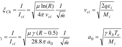
Using the values of current parameter so measured the ratio between current and the onset current (ξ ) has been calculated using both Choueiri’s1, 5 (Eq. 4) and Tikhonov’s6 (Eq. 5) formulas
i i ci ci ci Ch M q v m I v R I I ε π μ ξ 2 4 ) ln( = = =
& (4)
i e b ci Ti M T k a m I a R I I γ π γ μ
ξ = = − 0 =
0 8 . 28 ) 5 . 0 (
& (5)
[image:6.595.198.406.110.257.2]The values found using the data reported in this paper and the temperatures in Ref 7 are reported below
Table 2. ξ parameter.
Shot energy 1666 J 2000 J 2333 J 2666 J 3000 J
Eq. 4 0.63 0.68 0.7 0.76 0.6
Eq. 5 0.7 0.75 0.77 0.83 0.68
The values of ξ in Table 2 are high enough to justify the high level of ionization found in Ref 7 and, at the same time, low enough to avoid the arise of problems related to the onset.
B. Ablated mass measurement
To measure the ablated mass the propellant bars have been weighted before and after a series of shots. The number of shots required to ablate the quantity of propellant needed to achieve an acceptable accuracy varies from about 200 shots at low energies up to 100 at the highest ones.
Due to the very long time required to perform this kind of measurement data are still not available for all the energies and all the applied field intensities. The data collected up to now are reported below where with the shaded cells we indicate that for those operating conditions data were not measured while, as said before, with the dash we indicate conditions where the thruster does not work.
Table 3. Mass ablated per shot. The shaded cells indicated where data were not measured.
Shot Energy 1666 2000 2333 2666 3000
B = 0 T 1.15 1.45 1.65 1.66 2.02
B = 0.21 T - 0.82 1.38
B = 0.36 T - - - 1.47
Bad working region
[image:6.595.202.401.315.391.2]7
The mass ablated per shot is quite sensible to the application of the magnetic field. This can be explained noting that the applied field, moving the discharge downstream the anode, tend to reduce the area of the propellant bars affected by the discharge proportionally reducing the ablation.
At low energies this effect could be strong enough to reduce the area of the propellant bars affected by the discharge so much that the ablated mass is insufficient to sustain the discharge hence producing the deformation of the current curve observed in Fig. 6 and eventually preventing the thruster from working.
C. Impulse bit measurement
Because of the thruster was operated in quasi steady mode with shots of the order of one millisecond the values of the impulse bit Ib will be presented instead of the values of thrust.
Table 4. Impulse bit values for different energies and applied field intensities, mN s
Shot energy 1666 J 2000 J 2333 J 2666 J 3000 J
B = 0 T 9.31 12.74 15.59 18.57 20.87
B = 0.21 T 12.01 15.36 17.53 19.86 22.67
B = 0.28 T - 16.53 20.22 22.34 24.67
B = 0.36 T - - - 25.31 29.53
B = 0.43 T - - - - 32.19
1600 1800 2000 2200 2400 2600 2800 30005 10
15 20 25 30 35
E, J
Ib,
m
N⋅
s
B = 0 T B = 0.21 T B = 0.28 T B = 0.36 T B = 0.43 T
Figure 8. Impulse bit trend with shot energy
1000 1500 2000 2500 3000 3500 4000
10 15 20 25 30 35
I⋅B, A⋅T
Ib , m
N⋅
s
[image:7.595.115.482.238.699.2]B = 0.21 T B = 0.28 T B = 0.36 T B = 0.43 T exp lin interp
Looking at Fig. 8, 9 it can be noted how the impulse bit values vary linearly with the shot energy and with the product I·B as already found in most of the applied field MPD researches available in the literature1.
IV.
Comparison with theoretical expectations
The measured values of the impulse bit will now be compared with values calculated using the theory proposed by one of the authors2.
The angular velocity of the swirling motion induced by the axial applied field, the radius of the plasma jet and finally the thrust formula are reported below
⎟⎟ ⎠ ⎞ ⎜⎜ ⎝ ⎛ + = 2 1 ln c a r r m BI &
ω (6)
(
2 2)
0 2 4 self B i e B J B B M T k m r + = = F π μ & (7) 2 2 0 J B r a m& +
=F =
F (8)
The parameter a is defined as
2 3 2 2 2 8 8 2 2 2 0 0 9 J m B J J z z r k R r r v v a ⎟ ⎟ ⎠ ⎞ ⎜ ⎜ ⎝ ⎛ − + + − = ω ω ω (9)
where ωB and Rm are respectively the Langmuir frequency relative to the applied field
i B
M qB =
ω and the radius of the magnetic coil and k is the ratio between the Langmuir radius and the characteristic length of the magnetic field where the plasma jet detaches from the magnetic nozzle, its value should lie in the range 0.1 – 1.
[image:8.595.174.524.213.427.2] [image:8.595.150.449.510.627.2]The theoretical values of the impulse bit calculated with k=0.75 are reported below
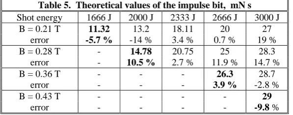
Table 5. Theoretical values of the impulse bit, mN s
Shot energy 1666 J 2000 J 2333 J 2666 J 3000 J
B = 0.21 T 11.32 13.2 18.11 20 27
error -5.7 % -14 % 3.4 % 0.7 % 19 %
B = 0.28 T - 14.78 20.75 25 28.3
error - 10.5 % 2.7 % 11.9 % 14.7 %
B = 0.36 T - - - 26.3 28.7
error - - - 3.9 % -2.8 %
B = 0.43 T - - - - 29
9
1000 1500 2000 2500 3000 3500 4000
10 15 20 25 30 35
I⋅B, A⋅T
Ib , m
N⋅
s
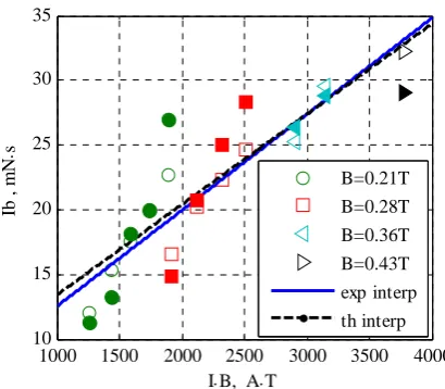
[image:9.595.196.401.112.291.2]B=0.21T B=0.28T B=0.36T B=0.43T exp interp th interp
Figure 10. Comparison between experimental and theoretical values of the Ib. Filled markers = theoretical values, empty markers = experimental values
The theoretical values show a satisfactory agreement with the experimental measurements with an overall trend very close to the experimental one.
V.
Conclusion
An applied field solid propellant MPD has been investigated. Threshold values of the applied field over which the thruster does not fire has been found. The threshold value of the applied field increases with increasing shot energy.
A possible explanation has been formulated based on the ablated mass behaviour with the applied field. Away from this threshold values the current parameter has show small variation confirming one of the hypotheses formulated in Ref 2.
The impulse bit value has been measured using a target free from any constraint relative to the power lines and free from any influence due to the presence of a magnetic field. The experimental values follow the trends founded in most of the applied field MPD investigation present in the literature1.
The impulse bit measurement have been compared with the theoretical values calculated using the formula proposed by one of the author showing a satisfactory agreement and showing almost the same overall trend
Future works will consist in the measurement of the ablated mass values for all the operating conditions and in continuing the investigation of the existence and behaviour of the applied field threshold value for solid propellant MPD.
References
1A.D. Kodys, E. Choueiri, “A Critical Review of the State-of-the-Art in the Performance of Applied-field Magnetoplasmadynamic Thruster”, 41st AIAA/ASME/SAE/ASEE Joint Propulsion Conference, Tucson, Arizona, USA, July 2005
2
M. Coletti, “Simple Thrust Formula for an MPD Thruster with Applied-Magnetic Field from Magnetic Stress Tensor”, AIAA-2007-5284, 43rd AIAA/ASME/SAE/ASEE Joint Propulsion Conference & Exhibit, Cincinnati, Ohio, USA, July 2007.
3
Paccani G.: "Experimental Analysis of a Coaxial Solid Propellant MPD Thruster with Segmented Anodes"; IEPC paper 93- 159, AIAA/AIDAA/DGLR/JSASS, 23rd International Electric Propulsion Conference, Seattle, Washinghton,13-16 Sept. 1993.
4
Paccani G., Petrucci L. and Deininger W.: “Scale Effects on Solid Propellant Coaxial MPD Thruster Performance”, J. of
Propulsion and Power”, AIAA Jrn, Vol. 19, No 3, May-June 2003.
5
E. Choueiri, “The Scaling of Thrust in Self-field MPD Thruster”, Journal of Propulsion and Power, n 14, pp744-753, September 1998
6 N. V. Belan, V. Kim, A. I. Oransky, V. B. Tikhonov, .Stationary Plasma Thrusters., Kharkov, 1989
7 M. Coletti, S. Ciampone, G. Paccani, G. Mazzitelli, “Spectroscopic Temperature Measurement in a Applied
8 Paccani G., Ravignani R., “Sulla misura indiretta della spinta di propulsori elettrici”, Aerotecnica Missili e Spazio, pp.
103-110, Jul.-Dec. 1995.
9
Paccani G., Ravignani R., “Sistema di misura della spinta di propulsori MPD”, Aerotecnica Missili e Spazio, pp. 42-51, Jan.-Jun. 1994.
10
Paccani G., “Solid Propellant Quasi-Steady MPD Thrusters with Self-Applied Magnetic Field”, AIAA-96-2704, 1996
11
Kuriki K., Okada O., “Experimental Study of Plasma Flow in a Magnetic Nozzle”, The Physics of Fluids, Vol 13, No 9, Settembre 1970.
12
Kuriki K., Okada O., “The Interaction between a Plasma Flow and a Magnetic Nozzle with Strong Hall Effect”, ISAS Report No 457, Vol 35, No 15, Dicembre 1970.
13
Kimura I., Arakawa Y., “Effect of Applied Magnetic Fields on Physical Processes in an MPD Arcjet”, AIAA Journal, Vol. 15, No. 5, pp.721-724, Maggio 1977.
14
A. Balestra, “Propulsori MPD con Campo Magnetico Applicato, Analisi Sperimentale”, Tesi di Laurea in Ingegneria Aerospaziale, University of Rome “La Sapienza”, 2007.
15