FAKULTI KEJURUTERAAN ELEKTRIK
SMALL SIZED ANIMATRONICS ROBOT
MECHANICAL CONSTRUCTION
NG WEI YU
DEGREE OF BACHELOR OF MECHATRONIC
ENGINEERING
APPROVAL
I hereby declare that I have read through this report entitle “Design and Development of Small Size Animatronics Robot Mechanical Construction” and found that it has comply
the partial fulfilment for awarding the degree of Bachelor of Mechatronics Engineering.
Signature : ...
Supervisor’s Name : CIK NUR MAISARAH BINTI MOHD SOBRAN
DESIGN AND DEVELOPMENT OF SMALL SIZE ANIMATRONICS ROBOT MECHANICAL CONSTRUCTION
NG WEI YU
A report submitted in partial fulfilment of the requirements for the degree of Bachelor of Mechatronics Engineering
Faculty of Electrical Engineering
UNIVERSITI TEKNIKAL MALAYSIA MELAKA
I declare that this report entitles “Design and Development of Small Size Animatronics Robot Mechanical Construction” is the result of my own research except as cited in the
references. The report has not been accepted for any degree and is not concurrently submitted in candidature of any other degree.
Signature : ...
Name : NG WEI YU
I
ACKNOWLEDGEMENT
II
ABSTRACT
ABSTRAK
III
TABLE OF CONTENTS
CHAPTER TITLE PAGE
ACKNOWLEDGEMENT I ABSTRACT II ABSTRAK III TABLE OF CONTENTS III LIST OF FIGURES VI LIST OF TABLES VIII
1 INTRODUCTION 1
1.1 Motivation 1
1.2 Problem Statement 3
1.3 Objective 4
1.4 Project Scope 4
2 LITERATURE REVIEW 5
2.1 Introduction 5
2.2 Animatronics robot 5
2.3 Criteria of legged robot 6
2.3.1 Linkage mechanism 6
IV
2.3.3 Types of actuator and controller 12
2.4 Benefits of legged robot 14
2.5 Summary of literature review 14
3 METHODOLOGY 16
3.1 Introduction 16
3.2 Overview of research 16
3.3 Design Methodology 18
3.3.1 Animatronics Design concept 18
3.3.2 Linkage design mechanism 19
3.3.3 Three Initial Design of Animatronics Robot 21
3.4 Fabrication Process 24
3.4.1 Fabrication material 24
3.4.2 Fabrication technique 25
3.4.3 Software interface 26
3.5 Hardware Development 27
3.5.1 Parts of animatronics robot 27
3.5.2 Construction of Animatronics Robot 30
3.5.3 Gear and linkage mechanism 33
3.5.4 Installation of Servo motor 34
3.5.5 Installation of controller board 36
3.6 Experiment 38
V
4 RESULT AND DISCUSSION 45
4.1 Experiment 1: Structural Analysis of robot 45
4.1.1 Centre of mass analysis 45
4.1.2 Stress, strain and displacement analysis 54 4.1.3 Summary of structural analysis 59 4.2 Experiment 2: Path trajectory planning study 60 4.3 Experiment 3: Real time hardware experiment 62 4.4 Result and discussion for Experiment 2 and 3 66
5 CONCLUSION AND FUTURE RESEARCH 68
5.1 Conclusion 68
5.2 Future research 69
VI
LIST OF FIGURES
FIGURE TITLE PAGE
[image:12.595.76.527.162.767.2]Figure 1.1 Robotic pack mule 2
Figure 3.1 Research flowchart 17
Figure 3.3 Normal cycle of walking horse 18
Figure 3.4 Beat movement of gaits for horse 19
Figure 3.5 Theo Jansen mechanism 20
Figure 3.6 Animatronics robot design 1 21
Figure 3.7 Animatronics robot design 2 22
Figure 3.8 Animatronics robot design 3 23
Figure 3.9 Poly Lactic Acid (PLA) plastic 24
Figure 3.10 MakerPi M2030 Metal Frame 3D printer 25
Figure 3.11 CAD software for 3D printer 26
Figure 3.12 Interface in CURA software 26
Figure 3.13 Single leg linkages mechanism 33
Figure 3.14 Gear and linkage construction 33
Figure 3.15 Servo motor and robot base 34
Figure 3.16 Instalment of motor with screw and nut 34 Figure 3.17 JX PDI-6221MG 360-degree servo motor 35 Figure 3.18 Installment of controller board and power supply 36
Figure 3.19 Arduino UNO R3 36
VII
Figure 3.21 Matlab simulation 40
Figure 3.22 Theo Jansen mechanism linkages 41
Figure 3.23 Complete hardware design of animatronics robot 43
[image:13.595.67.520.65.752.2]Figure 3.24 Data collecting procedure 44
Figure 4.1 Centre of mass for design 1 45
Figure 4.2 Design 1 centre of mass view 46
Figure 4.3 Mass properties for design 1 47
Figure 4.4 Centre of mass for design 2 48
Figure 4.5 Design 2 centre of mass view 49
Figure 4.6 Mass properties for design 1 50
Figure 4.7 Centre of mass for design 3 51
Figure 4.8 Design 3 centre of mass view 52
Figure 4.9 Mass properties for design 3 53
Figure 4.10 Stress analysis for design 1 54
Figure 4.11 Strain analysis for design 1 55
Figure 4.12 Displacement analysis for design 1 55
Figure 4.13 Stress analysis for design 2 56
Figure 4.14 Strain analysis for design 2 56
Figure 4.15 Displacement analysis on design 2 57
Figure 4.16 Stress analysis for design 3 58
Figure 4.17 Strain analysis for design 3 58
Figure 4.18 Displacement analysis on design 3 59
Figure 4.19 Trajectory path result comparison 66
VIII
LIST OF TABLES
TABLE TITLE PAGE
Table 2.1 Comparison of linkage mechanism 8
Table 2.2 Comparison of material and modelling method 11 Table 2.3 Comparison of actuator and controller 13
Table 3.1 Parts of animatronics robot 27
Table 3.2 Parts of animatronics robot 30
Table 3.3 Specification of JX PDI-6221MG servomotor 35 Table 3.4 Arduino Motor Control Shield L293D 37
Table 4.1 Simulation data result 60
Table 4.2 Hardware experiment average result 63 Table 4.3 Data of measured value vs actual value 65
1
CHAPTER 1
INTRODUCTION
1.1 Motivation
2
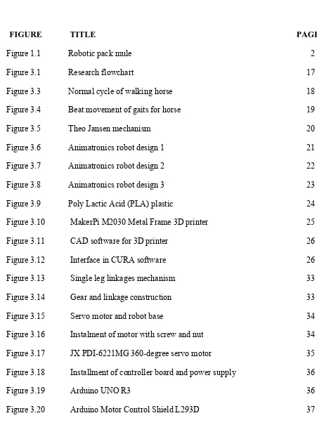
[image:16.595.186.425.200.335.2]In US, a robotic pack mule has been developed for US troops as a leg up on terrain condition and even for military vehicles as shown in figure 1.1. This mechanized legged robot capable of carrying all the gear soldiers and marines might need in combat. Marc Raibert, the president of Boston Dynamics also confidently said that the robotic pack mules might be use by combat troops by embedded with a Marine squad for an operational exercise. [2]
3
1.2 Problem Statement
Bioinspired legged robots or animatronics robots have become increasingly agile. Wheels are much easier to construct and control. Legs have distinct advantages over wheels due to the adapting principle and mechanism. [3] Wheeled robots face a major disadvantage with short instant elevation changes. Movement such as climbing stairs or steep jagged rock piles become a big problem for wheel vehicles thus many researchers tends to find many alternative solutions to solve this kind of problem. While climbing stairs, the robot need to ascend and traverse natural slopes with many different slopes on terrain with variation of degree and climb over small obstacles in rough terrain. The uneven surface slopes can be up to 50 degrees until 75 degrees and difficult for wheeled robot to travel. [4] Moreover, the slope degree for stairs can be up to 90 degrees which is impossible for wheeled robot to travel. Besides, ordinary vehicles unable to move smoothly on the mountains roads or other difficulties and this may cause the limitation in transportation work. Since, the floor is covered with portions of the building collapsed and even the entrances are blocked with obstacles. This make the building unsafe for people to enter due to the poor footing in building. Then, the rescue squad unable to investigate from the area of origin to aid for the rescue mission. Moreover, a small size robot is pertinent to ensure that the area of movement can be expand and more task can be carry out. Therefore, the main problem we need to solve is about the short elevation of legged robot to improve its flexibility and ability to travel along different kind of surfaces and spaces.
4
1.3 Objective
The main intention of the small size animatronics robot mechanical construction is to design and develop the mechanical part of a device that has the ability to move along uneven or rough terrain. By comparing of the design from many researchers, it will give an opportunity in choosing the best design to use in various applications. However, many data analysis and performance test need to be carry out throughout the project to make sure that the project is applicable in daily life. This project embarks on the objectives as shown below: 1. To design and develop the mechanical part of robot that has an ability travel on small
area.
2. To fabricate and analyse the designed robot using SolidWorks and Matlab modelling method.
3. To evaluate the performance of animatronics robot in term of validity and accuracy.
1.4 Project Scope
The research limitation in this project defines the range of data measurement and also evaluation parameters when conducting or designing the prototype of hardware to achieve the objectives as mentioned in previous subchapter. The main focus of this project is on the design and fabrication the mechanical parts of a small size animatronic robot followed by suitable analysis and performance test using proper method. The scopes of the project are listed below:
1. Come out with three feasible designs of small size animatronics robot.
2. Study the mechanical construction use to drive the mechanism of legged robot. 3. Determine the parameters that will affect the characteristics and performance of
animatronics robot.
4. Identify the suitable types of actuator needed to actuate the animatronics robot. 5. Analyse the design of animatronics robot using Solidworks and Matlab simulation
5
CHAPTER 2
LITERATURE REVIEW
2.1 Introduction
This chapter explains a brief overview about my project which is small size animatronics robot mechanical construction. After studying all of the literatures, the various types of mechanism and designs are described and analysed based on researchers’ findings.
2.2 Animatronics robot
6
2.3 Criteria of legged robot
There are many criteria has been discussed for the construction of robot such as types of mechanism, degree of freedom, types of actuator, type of materials selection, software used, controller used and also number of legs for the robot. Lastly, the benefits of legged robot are discussed.
2.3.1 Linkage mechanism
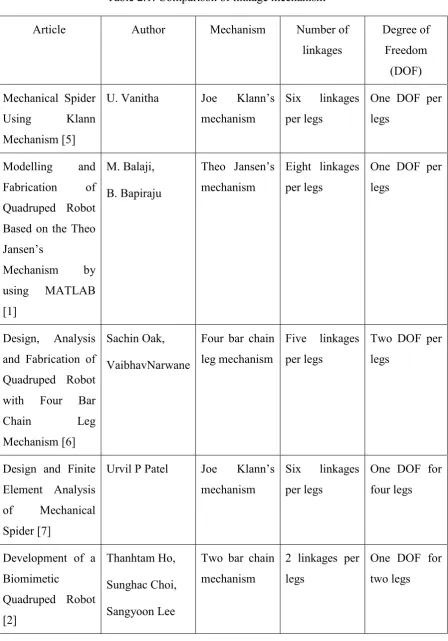
Based on the papers, the two most effective leg mechanisms are Joe Klann’s mechanism which resembles a spider leg and Theo Jansen’s mechanism which resembles a human leg. Jansen’s linkage mechanism designed by kinetic sculptor to simulate a smooth walking motion and Klann linkage mechanism provides many benefits in more advanced walking vehicles. [5] However, a mechanical spider using Klann mechanism is chosen since it has more advantages than Jansen mechanism. Klann mechanism is simpler and less complicated with lesser linkage for movement. The mechanism is a six-bar linkage with one degree-of-freedom mechanism on each leg that constructed from six links and seven joints. These six linkages are connected to two shafts, with three linkages space equally divided on each side of the frame.
Moreover, Theo Jansen’s mechanism is 8 bar linkages with one degree of freedom on each leg. The 8 bar linkages are a combination of 4 bar linkage and two 3 bar linkages. [1] Moreover, Hrones-Nelson and Theo Jansen mechanism are compared due to the similarity of their designs which are both comprised solely of rigid triangular bodies attached to four-bar linkages. Theo Jansen mechanism comprised of two four bar linkages attached to each other in series with only one of the linkages driven by the shaft and crank.
7
8
Table 2.1: Comparison of linkage mechanism
Article Author Mechanism Number of
linkages
Degree of Freedom
(DOF) Mechanical Spider
Using Klann Mechanism [5]
U. Vanitha Joe Klann’s mechanism
Six linkages per legs
One DOF per legs
Modelling and Fabrication of Quadruped Robot Based on the Theo Jansen’s
Mechanism by using MATLAB [1]
M. Balaji, B. Bapiraju
Theo Jansen’s mechanism
Eight linkages per legs
One DOF per legs
Design, Analysis and Fabrication of Quadruped Robot with Four Bar
Chain Leg
Mechanism [6]
Sachin Oak, VaibhavNarwane
Four bar chain leg mechanism
Five linkages per legs
Two DOF per legs
Design and Finite Element Analysis of Mechanical Spider [7]
Urvil P Patel Joe Klann’s mechanism
Six linkages per legs
One DOF for four legs
Development of a Biomimetic
Quadruped Robot [2]
Thanhtam Ho, Sunghac Choi, Sangyoon Lee
Two bar chain mechanism
2 linkages per legs
9
2.3.2 Fabrication and modelling method
Based on the research, Theo Jansen mechanism comprised of two four bar linkages attached to each other in series with only one of the linkages driven by the shaft and crank. A four-legged robot made by using Theo Jansen’s mechanism and the composed of the mechanism is model by using MATLAB and linear motions are observed on the graph for the Theo Jansen based quadruped robot. For the modelling and fabrication of product, the linkage lengths were taken directly from Theo Jansen’s book “The Great Pretender”. [1] The fabrication involves many complicated processes like cutting of material, selection of motor, drilling of centre rod, fixing motor and final finishing work. The analysis of the robot performance is done by using the AutoCAD software and MATLAB software. The analysis of trajectory leg movement is done by simulation of mechanism using MATLAB to record the X and Y position of end effector. The coordinate system of its legs path is then recorded and tabulated in table form.
For analysis and fabrication of quadruped robot with four bar chain leg mechanism, the robot was first design and develop using CAD model software to ensure overall dimensions of robot are fixed. [6] A table of joint angles for the hips and knees is then tabulated as results of experiment. Further discussion is made to study the different exist each of the joint angles. The different of angles are because of restriction to servomotor revolution and mounting arrangement on quadruped.
10
heavy loads. However, there are a few limitations for this design like high power source, limited speed and smoothness of motion.