Rochester Institute of Technology
RIT Scholar Works
Theses Thesis/Dissertation Collections
4-1-2009
Communication framework for distributed
computer vision on stationary and mobile
platforms
Christopher Armenio
Follow this and additional works at:http://scholarworks.rit.edu/theses
This Thesis is brought to you for free and open access by the Thesis/Dissertation Collections at RIT Scholar Works. It has been accepted for inclusion in Theses by an authorized administrator of RIT Scholar Works. For more information, please [email protected].
Recommended Citation
A Communication Framework for Distributed Computer
Vision on Stationary and Mobile Platforms
by
Christopher Armenio
A Thesis Submitted in Partial Fulfillment of the Requirements for the Degree of Master of Science in Computer Engineering
Supervised by
Dr. Andreas Savakis Professor and Department Head Department of Computer Engineering
Kate Gleason College of Engineering Rochester Institute of Technology
Rochester, New York April 2009
Approved By:
Dr. Andreas Savakis
Professor and Department Head, Department of Computer Engineering Primary Advisor
Dr. Roy Czernikowski
Thesis Release Permission Form
Rochester Institute of Technology
Kate Gleason College of Engineering
Title:
A Communication Framework for Distributed Computer Vision on Stationary and Mobile Platforms
I, CHRISTOPHER ARMENIO, HEREBY GRANT PERMISSION TO THE WALLACE MEMORIAL LIBRARY TO REPRODUCE MY THESIS IN WHOLE OR PART.
_________________________________ Christopher Armenio
Dedication
Dedicated to all those who see the value of personal projects and who learn through curiosity, error, and dedication. You will go far…
Just to name a few:
Mark Baybutt
Mateusz Wyganowski Nathan Pendleton Alex Sojda Drew Stephens Tayeb Karim Greg VonPless Chris Connet Greg Needel David Rusbarski
And to those who wander along the path of life:
You open our eyes to the beauty of living life without need of a destination and allow us to question not only our actions, but ultimately ourselves. Through you I have learned more than I can say about life, and myself…wherever your meandering leads, may your journey be filled with happiness and, above all else, love.
Acknowledgements
Dr. Savakis Dr. Czernikowski Dr. Yang
Abstract
Recent advances in the complexity and manufacturability of digital video cameras
coupled with the ubiquity of high speed computers and communication networks have led
to burgeoning research in the fields of computer vision and image understanding. As the
generated vision algorithms become increasingly complex, a need arises for robust
communication between remote cameras on mobile units and their associated distributed
vision algorithms.
A communication framework would provide a basis for modularization and
abstraction of a collection of computer vision algorithms; the resulting system would
allow for straightforward image capture, simplified communication between algorithms,
and easy replacement or upgrade of existing component algorithms.
The objective of this thesis is to create such a communication framework and
demonstrate its viability and applicability by implementing a relatively complex system
of distributed computer vision algorithms. These multi-camera algorithms include body
tracking, pose estimation and face recognition.
Although a plethora of research exists documenting individual algorithms which
may utilize multiple networked cameras, this thesis aims to develop a novel way of
sharing information between cameras and algorithms in a distributed computation
system. In addition, this thesis strives to extend such an approach to using both stationary
and mobile cameras. For this application, a mobile computer vision platform was
Table of Contents
CHAPTER 1 INTRODUCTION... 1
1.1 PURPOSE... 5
CHAPTER 2 IOBROKER ARCHITECTURE ... 7
2.1 IOBROKER SELECTION... 7
2.2 IOBROKER PURPOSE... 8
2.2.1 Fault Isolation... 8
2.2.2 Resource Partitioning ... 9
2.2.3 Modularity ... 9
2.2.4 Compilation time... 9
2.3 IOBROKER OVERVIEW... 10
2.3.1 Messages ... 11
2.3.1.1 Raw Message Format ... 11
2.3.1.1 iobMessage Structure ... 12
2.3.2 iobClient... 14
2.3.2.1 Connecting to the ioBroker ... 15
2.3.2.2 Posting data to the ioBroker ... 15
2.3.2.3 Subscribing to and receiving messages ... 16
2.3.3 brokerClient ... 17
2.3.4 ioBroker ... 18
2.4 IOBROKER DETAILS... 19
2.4.1 ioBroker ... 19
2.4.1.1 Command Line Options ... 19
2.4.1.2 Configuration File ... 19
CHAPTER 3 - EXTENSIONS TO IOBROKER ... 21
3.1ORIGINAL IOBCLIENT NETWORKING... 21
3.2NEW IOBROKER NETWORKING... 23
3.2.1 Overall System Architecture ... 23
3.2.2 BrokerBridge Addition... 24
3.2.3 Message Additions ... 25
3.2.3.1 BrokerAnnounce Message ... 25
3.2.3.2 BrokerResponse Message... 26
3.2.3.3 BrokerAnnounceProxy Message ... 27
3.2.4 ioBroker Discovery Process... 28
3.2.4.1 Hub ioBrokers ... 29
3.2.4.2 Spoke ioBrokers ... 30
3.2.4.3 Network Initialization ... 30
3.2.5 Message Routing ... 32
3.3 IOBSESSION LAYER... 36
3.3.1 iobSessionLayer Internal Organization ... 37
3.3.2 classID Naming Conventions... 38
3.3.2.1 classID format ... 38
3.3.3 Datagram Messages... 40
3.3.4 Remote Procedure Calls ... 40
3.3.4.1 Registering an RPC ... 40
3.3.4.2 Executing an RPC ... 41
3.3.4.3 RPC Request Message ... 43
3.3.4.4 RPC Response Message ... 44
4.1.1 Configuration Options ... 46
4.1.1.1 Command Line Parameters ... 46
4.1.1.2 Configuration File Contents ... 47
4.1.2 lensCalibration ... 48
4.1.2 camClient ... 50
4.1.2.1 Video streaming ... 50
4.1.2.2 Relative pan/tilt ... 50
4.1.2.3 Global pan/tilt... 51
4.1.2.4 Focal length zooming ... 51
4.1.2.5 Angle of view zooming ... 51
4.2 ROI_HAARDETECTOR PROCESS... 52
4.2.1 Command Line Parameters ... 53
4.3 ROIVIEWER PROCESS... 53
4.3.1 Command Line Parameters ... 54
4.4 TRIANGULATOR PROCESS... 55
4.4.1 Command Line Parameters ... 55
4.4.2 Configuration File ... 56
4.4.3 CALCULATION DETAILS... 56
4.5 MOBILESLEWING PROCESS... 62
4.5.1 Command Line Parameters ... 62
4.5.2 Configuration File ... 62
4.5.3 Calculation Details ... 63
CHAPTER 5 PROTOTYPE SYSTEM OPERATION AND RESULTS... 65
5.1PROTOTYPE SYSTEM OPERATION... 65
5.1.1 Image Acquisition ... 65
5.1.2 ROI Detection ... 66
5.1.3 ROI Triangulation... 66
5.1.4 Zooming ... 67
5.2PROTOTYPE SYSTEM RESULTS... 67
5.2.1 Framerate Tests ... 68
5.2.1.1 Local Processes ... 68
5.2.1.2 Remote Processes... 72
5.2.2 Robustness Tests ... 75
5.2.2.1 Results Analysis ... 76
5.2.3 Position Estimation Tests... 76
5.2.3.1 Results Analysis ... 84
5.2.3.2 Z-direction Error Compensation Using Simple Average... 86
5.2.3.2 Z-direction Error Compensation Using Linear Bias... 89
CHAPTER 6 CONCLUSIONS AND FUTURE WORK ... 93
6.1CONCLUSIONS... 93
6.2FUTURE WORK... 94
List of Figures
FIGURE 1.SYSTEM ARCHITECTURE OF PRISMATICA. ... 2
FIGURE 2.PROPOSED MASCOTSYSTEM ARCHITECTURE [7],[8]. ... 3
FIGURE 3.ACTIVITY/IDA RELATIONSHIP [7],[8]. ... 4
FIGURE 4.SYSTEM ARCHITECTURE OF [4]... 4
FIGURE 5.BLACKBOARD DISTRIBUTION [4]. ... 5
FIGURE 6, IOBROKER ARCHITECTURE OVERVIEW... 10
FIGURE 7. IOBROKER RAW MESSAGE FORMAT. ... 11
FIGURE 8.EXAMPLE IOBMSG MEMORY TRANSFER. ... 13
FIGURE 9. IOBMSG STRUCTURE... 14
FIGURE 10. IOBROKER SUBSCRIPTION MATCHING PROCESS. ... 17
FIGURE 11.CONFIGURATION FILE EXAMPLE DIRECTIVE... 19
FIGURE 12.CONFIGURATION FILE DIRECTIVE HIERARCHY... 20
FIGURE 13.ORIGINAL IOBCLIENT NETWORKING. ... 21
FIGURE 14.DUPLICATED TRAFFIC. ... 22
FIGURE 15.SINGLE POINT OF FAILURE. ... 22
FIGURE 16.BROKERBRIDGE NETWORKING ARCHITECTURE. ... 25
FIGURE 17. IOBROKER ‘ANNOUNCE’ MESSAGE FORMAT. ... 26
FIGURE 18. IOBROKER ‘BROKERRESPONSE’ MESSAGE FORMAT. ... 27
FIGURE 19. IOBROKER ‘BROKERANNOUNCEPROXY’ MESSAGE FORMAT. ... 28
FIGURE 20.MESH/STAR IOBROKER NETWORK. ... 29
FIGURE 21.SPOKE-HUB CONNECTION SEQUENCE... 31
FIGURE 22.SPOKE-SPOKE CONNECTION SEQUENCE. ... 32
FIGURE 23.REMOTE SUBSCRIPTION SEQUENCE. ... 34
FIGURE 24.ROUTING LOOP TOPOLOGY... 34
FIGURE 25.FIRST STEP IN POTENTIAL ROUTING LOOP... 35
FIGURE 26.COMPLETION OF POTENTIAL ROUTING LOOP. ... 36
FIGURE 27.AVOIDANCE OF ROUTING LOOP. ... 36
FIGURE 28. IOBSESSIONLAYER HIERARCHY. ... 37
FIGURE 29.INTERNAL STRUCTURE OF IOBSESSIONLAYER OBJECT... 38
FIGURE 30.STANDARDIZED CLASSID FORMAT. ... 38
FIGURE 31.DATAGRAM MESSAGE STRUCTURE... 40
FIGURE 32.RPCREQUEST MESSAGE STRUCTURE. ... 43
FIGURE 33.RPCRESPONSE MESSAGE STRUCTURE... 44
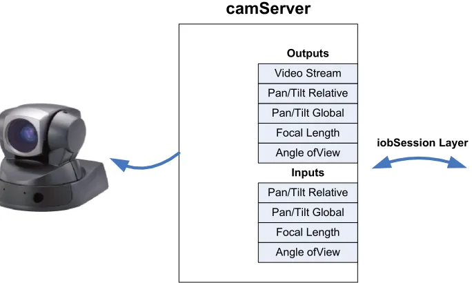
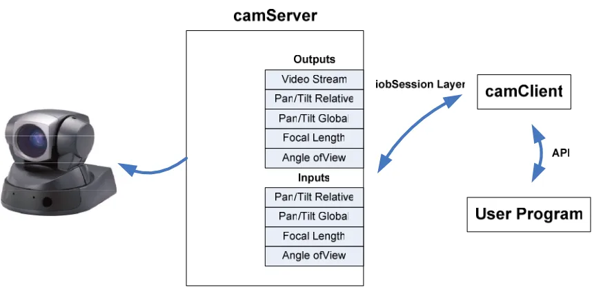
FIGURE 34. CAMSERVER FUNCTIONAL DIAGRAM. ... 46
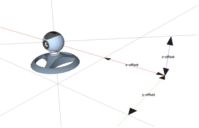
FIGURE 35.'CAMERA::LOCATION’ PARAMETERS... 48
FIGURE 36.'CAMERA::CAMERAPAN' AND 'CAMERA::CAMERATILT' PARAMETERS. ... 48
FIGURE 37. CAMCLIENT CONTROL STRUCTURE. ... 50
FIGURE 38.ROI LINE CONVERGENCE. ... 59
FIGURE 39.INTERSECTION PLANE CREATION... 60
FIGURE 40.INTERSECTION PLANE WITH EXAMPLE DISTANCES. ... 61
FIGURE 41.‘MOBILESLEWING’PAN CALCULATION DIAGRAM... 63
FIGURE 42.‘MOBILESLEWING’TILT CALCULATION DIAGRAM. ... 64
FIGURE 43.PROCESS AND DATAFLOW OF EXAMPLE SYSTEM. ... 65
FIGURE 44.CLASSIDS OF IMAGES PRODUCED BY THE ‘CAMSERVER’ PROCESSES... 66
FIGURE 45.CLASSIDS OF ROIS PRODUCED BY THE ‘ROI_HAARDETECTOR’ PROCESSES... 66
FIGURE 46.CLASSID OF 3D LOCATION PRODUCED BY ‘TRIANGULATOR’ PROCESSCAM1. ... 66
FIGURE 47.SUPERIMPOSED MESSAGE NUMBER. ... 69
FIGURE 48.GRAPH OF LOCAL PROCESS AVERAGE FRAMERATES. ... 71
FIGURE 49.GRAPH OF REMOTE PROCESS AVERAGE FRAMERATES. ... 74
FIGURE 50.CAMERA LOCATIONS IN X-ZPLANE. ... 77
FIGURE 52.ROI CAPTURE ON COMPUTER 1... 78
FIGURE 53.ROI CAPTURE ON COMPUTER 2... 79
FIGURE 54.TRIANGULATED POSITION OF SUBJECT. ... 79
FIGURE 55.IMAGE CAPTURE OF ESTIMATED POSITION... 80
FIGURE 56.POSITION ESTIMATION RESULTS... 84
FIGURE 57.ESTIMATED POSITION LOCATIONS ADJUSTED BY SIMPLE BIAS... 89
List of Tables
TABLE 1. IOBROKER RAW MESSAGE FORMAT. ... 11
TABLE 2. IOBMSG STRUCTURE... 13
TABLE 3. IOBCLIENT SUBSCRIPTION PARAMETERS... 16
TABLE 4. IOBROKER COMMAND LINE PARAMETERS... 19
TABLE 5. IOBROKER CONFIGURATION FILE DIRECTIVES... 20
TABLE 6. IOBROKER 'ANNOUNCE' MESSAGE FIELDS. ... 26
TABLE 7. IOBROKER ‘BROKERRESPONSE’ MESSAGE FIELDS. ... 27
TABLE 8. IOBROKER ‘BROKERANNOUNCEPROXY’ MESSAGE FIELDS... 28
TABLE 9.NEW IOBROKER CONFIGURATION FILE FIELDS... 29
TABLE 10.ADDED IOBROKER CONFIGURATION FILE FIELDS. ... 30
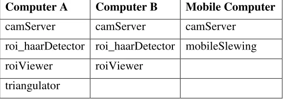
TABLE 11.PROCESS BREAKDOWN PER COMPUTER. ... 45
TABLE 12.'CAMSERVER'COMMAND LINE PARAMETERS. ... 46
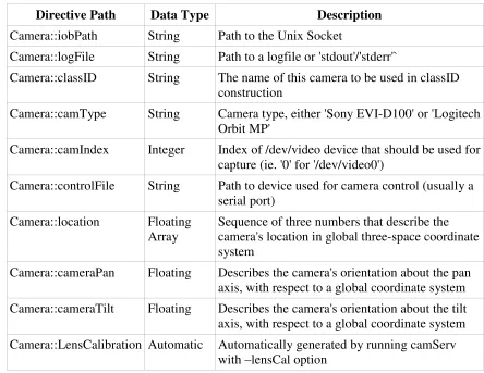
TABLE 13.'CAMSERVER'CONFIGURATION FILE FIELDS. ... 47
TABLE 14.‘ROI_HAARDETECTOR’COMMAND LINE PARAMETERS. ... 53
TABLE 15.'ROIVIEWER'COMMAND LINE PARAMETERS... 54
TABLE 16.'TRIANGULATOR'COMMAND LINE PARAMETERS. ... 55
TABLE 17.'TRIANGULATOR'CONFIGURATION FILE FIELDS... 56
TABLE 18.'MOBILESLEWING'COMMAND LINE PARAMETERS. ... 62
TABLE 19.'MOBILESLEWING'CONFIGURATION FILE FIELDS. ... 62
TABLE 20.TEST SYSTEM PARAMETERS. ... 68
TABLE 21.LOCAL PROCESS AVERAGE FRAMERATE RESULTS. ... 70
TABLE 22.REMOTE PROCESS AVERAGE FRAMERATE RESULTS. ... 73
TABLE 23.ROBUSTNESS TEST RESULTS... 75
TABLE 24.CAMERA LOCATION IN 3D SPACE. ... 78
TABLE 25.POSITION ESIMATE RESULTS FOR SUBJECT 1 ... 81
TABLE 26.POSITION ESTIMATE RESULTS FOR SUBJECT 2. ... 82
TABLE 27.POSITION ESTIMATE RESULTS FOR SUBJECT 3. ... 83
TABLE 28.AVERAGE ERRORS. ... 86
TABLE 29.Z-BIAS CALCULATION TABLE. ... 87
TABLE 30.Z-DISTANCES AND ERRORS ADJUSTED BY SIMPLE BIAS. ... 88
TABLE 31.AVERAGE Z ERROR CALCULATIONS FOR LINEAR OFFSET. ... 90
Glossary
BrokerBridge The portion of the ioBroker executable that connects to other
ioBrokers and exchanges data.
brokerClient The portion of the ioBroker that is responsible for talking with a
specific process. For every process using the ioBroker, there is at least one brokerClient.
camServer An executable that provides control and image capture of a camera
attached to the computer.
classId A string of text describing the content of an ioBroker message.
Haar Cascade A method of detecting the presence of a specified object within a
given image.
Intrinsic matrix A matrix used to describe distortion caused by the lens of a camera.
iobClient A library used to communicate with the ioBroker.
ioBroker An executable that routes messages between processes on a single
computer as well as processes on multiple computers.
iobSessionLayer A library used to process RPC mechanisms as well as multi-topology
message routing.
IPC Inter-process communication, used to refer to communication between multiple processes on a single computer.
ROI Region of interest, an area in an image that contains an item of interest.
RPC Remote procedure call, the ability to initiate a function or process in a process that is separate from the calling process.
Sockets A mechanism provided by programming languages of exchanging
Chapter 1 Introduction
The large amount of research currently being performed in the field of computer vision
would not be possible without recent advances in available computational power and the
extremely large amount of data produced by cameras for input into these vision
algorithms [6]. Today, a standard, commercially available webcam typically has
resolution between 320x240 pixels and 800x600 pixels. Assuming a mid-range resolution
of 640x480 pixels, the cameras likely produce 8-bit color images, requiring 3 bytes of
data per pixel:
frame bytes , = pixel bytes column pixels row
pixels 921600 1
3 480
640
⋅
⋅ (1)
Per frame, a vision algorithm is required to process 921,600 bytes. Assuming that
the goal for real-time processing is approximately 15 frames per second (roughly half that
of human vision), the algorithm must be able to cope with a data rate of:
921,600bytes frame
15 frames
1 sec =
13,824,000bytes
sec (2)
Processing 13,824,000 bytes per second is a non-trivial data rate; it is no wonder that
until recently, many computer vision algorithms were not computationally feasible.
It is fairly obvious that aside from specialized hardware, a single computer is not
be able to handle video streams from multiple cameras, which in some cases generate
over 26TB of data per day [4]. This presents the need for distributed processing
frameworks with the ability to partition data processing among many computers, possibly
in different geographic locations. Distributed processing is not new, and as such, there are
In [5], most processing takes place at or near the cameras using what is known as
an ‘Intelligent Camera System’. In such an approach, single or multiple cameras are
paired with a processing board that is capable of processing the respective input streams
and only relaying important feature data to the rest of the system.
Figure 1. System Architecture of PRISMATICA.
Figure 1 shows the central server (MIPSA) which communicates with one or
more devices using the Device Communication Object (DCO). The DCOs relay
information using the TAO or object request broker. The broker allows devices to request
information from other devices as shown by the dashed line between Device A and
Device B. Such an approach creates a distributed network at the embedded level,
however, it typically requires custom hardware which generally increases costs compared
to common off the shelf hardware (COTS).
The work in [7] and [8] presents an approach which takes advantage of the
availability of COTS hardware by utilizing a network of multiple full-size computers.
Each computer is connected to one or more cameras and attempts to perform intensive
Figure 2. Proposed MASCOT System Architecture [7],[8].
Data in this architecture is passed from activity to activity through the use of an
Intercommunication Data Area (IDA). The purpose of the IDA is to provide a
multi-thread safe mechanism for passing data between activities, which alleviates the worry of
thread synchronization from users of the architecture. The downside to such a system is
that processes cannot be dynamically added or removed from the system at run-time,
which prevents the end-user from adding or removing activities or processes as situations
Figure 3. Activity/IDA relationship [7], [8].
Figure 4. System Architecture of [4].
In contrast with the static system presented in [7] and [8], [4] presents a system
which supports dynamic process allocation and execution using a blackboard
architecture. In this system, a weakly consistent blackboard is used to distribute
incoming data from the surveillance zones to the appropriate data consumers or
processing algorithms. Vision processing algorithms are displayed in Figure 4 by the
control centers at the top center, while cameras are represented by a Surveillance Zone, or
Figure 5. Blackboard Distribution [4].
The blackboard itself is distributed among separate processing nodes on a vertical
basis, that is, different levels represented in Figure 5 are placed on separate machines. In
this model each machine, or level in the network, represents a step into a higher level of
abstraction.
Such a system is not without its downfalls: since the blackboard used in the
system cannot handle the significant volume of data produced by the cameras, individual
video streams are routed using virtual circuits to their respective consumers, rather than
through the blackboard. While this takes a non-trivial load off the blackboard, it does
however, diminish the intent of having a single communication architecture for the entire
system, introducing a complex network of virtual circuits specifically for video
information.
1.1 Purpose
The complexity of the aforementioned processing systems, coupled with the large
amounts of respective input data presents a significant hurdle in terms of overhead for
many researchers. In [2] and [3], Erhard and Mullen created a relatively simple
separate computers. This communication system was written specifically for their work,
and likely required a non-trivial amount of time to complete.
At the same point, a large, scalable system such as [4] or [5] may be somewhat of
an overkill in less complex situations. This thesis, therefore, posits a lightweight
communication framework designed specifically to support small to medium sized
computer vision systems. The framework was designed to facilitate modularization and
abstraction of the component algorithms and allow for easy upgrade/replacement of its
algorithms. In terms of distributed computing, the framework was specifically designed
to support communication between processes local to a single machine, as well as
processes running on remote machines. Finally, special care was taken throughout to
make the end result simple and easy to use.
This thesis is organized as follows. Chapter 2 describes the ioBroker
communication architecture. This architecture serves as the basis upon which this work is
built. Chapter 3 describes the extensions made to the ioBroker architecture expressly for
support computer vision applications. Chapter 4 details the components that comprise an
example system implemented to demonstrate the utility of the developed architecture.
The overall operation of said system is detailed in Chapter 5, concentrating on the
interactions of the modules detailed in Chapter 4. Finally, Chapter 6 discusses the results
obtained from the example system, including benchmarks of the communication
Chapter 2 ioBroker Architecture
The first ioBroker Architecture was developed by Greg Rowe at Impact Technologies in
Rochester, NY for use on an embedded linux data acquisition system. The original
purpose of ioBroker was to provide a mechanism for the distribution of both high and
low rate data to multiple processes running on a single CPU. Since ioBroker was
originally developed for use on embedded linux systems, it is built around the sockets
API taking advantage of both Unix domain sockets and TCP/IP sockets [12]. The use of
these standard constructs provides for reliable, high-speed data transfer and easy porting
to any system which supports sockets (Windows, Mac, and nearly all linux/unix flavors).
The primary contribution of this thesis is extending ioBroker for use in computer
vision applications. To set up the initial framework, the following sections detail the
inner-workings of ioBroker in its original format.
2.1 ioBroker Selection
The ioBroker architecture is only one of a growing number of inter-process
communication mechanisms. Its selection as the mechanism of choice for this work relies
on a number of distinct advantages that ioBroker has over its counterparts. To begin with,
ioBroker is not only an inter-process communication architecture, but it is also an inter-pc
communication architecture. Common IPC mechanisms such as DBUS, used rather
extensively in Linux operating systems, are designed specifically for communications
within a computer. Since this work seeks to support communication between multiple
computers, IPC mechanisms such as DBUS were excluded from consideration.
inter-computer communication, however its features and capabilities lead to a sometimes
overwhelming programmer interface. This interface usually requires a separate Interface
Description Language or IDL and associated code generator just to get started. Overall,
for envisioned computer vision systems for which this architecture is targeted, CORBA is
overkill.
Finally, because the ioBroker architecture is open source and rather
straightforward to use, it is extremely easy to modify and extend the architecture to add
features that may not be considered in this work. For complex architectures such as
DBUS, CORBA, and the like, their extremely large feature sets make even the simplest
modification a daunting task.
2.2 ioBroker Purpose
The purpose of the ioBroker architecture is to facilitate the distribution of data between
multiple processes running on a CPU. In data processing applications, especially in
complex systems, it is often desirable to split tasks into standalone processes for a
number of reasons outlined below.
2.2.1 Fault Isolation
Errors will undoubtedly crop up when programming, even in the most carefully
engineered systems. As the complexity of a single process increases, it has been shown
that the likelihood of errors increases exponentially [11]; thus, keeping processes as
simple as possible is highly desirable. In addition, should an unrecoverable error occur in
2.2.2 Resource Partitioning
For more complex systems, or systems running in resource constrained environments, the
ability to divide processes between multiple CPUs, based upon processor usage or
available resources, is highly advantageous. Although ioBroker itself only provides
rudimentary support for such distribution, simple systems can be devised which take
advantage of this ability.
2.2.3 Modularity
Dividing a single complex process into multiple simple processes inherently requires the
definition of inter-process interfaces. In order for process A to know how to send data to
process B, process A and B must agree on what format the data should be in. By
inherently requiring these interfaces, the system designer can conceivably design multiple
processes that perform the same function in different manners. The designer can then
decide which process will work better in-situ and swap each process out simply by
terminating the unwanted process and starting the new one.
2.2.4 Compilation time
Similar to the advantages of modularization for differing implementations, in a complex
single-process system, any programmatic change to one function or task requires
re-compilation of the entire system. Over the development period of the system, this can
lead to a large amount of wasted time and CPU resources. By dividing the system into
multiple standalone processes, the same changes only affect one or two executables,
which requires significantly less compilation time.
The easiest way of partitioning a single complex process into multiple relatively
standalone process that consumes data and produces a result. However, breaking a single
process up in this fashion introduces the problem of data transfer. In the original complex
single process, data could be passed around from function to function or task to task
rather easily, since all existed in a common address space. With partitioning, the
functions or tasks are split into processes that no longer share the same address space and
communication and synchronization become a large issue; this is where ioBroker fits in.
2.3 ioBroker Overview
The ioBroker architecture consists of three main components: the ioBroker executable,
the brokerClient, and the client libraries, otherwise known as iobClient. The first two
components, ioBroker and brokerClients, form the overall standalone executable known
as the ioBroker, while the client libraries are the only part of the system that the
programmer will directly access.
Figure 6, ioBroker Architecture Overview.
On a very high level, the ioBroker architecture is simply a mechanism for
2.3.1 Messages
2.3.1.1 Raw Message Format
The sockets interface is essentially used to transfer a chunk of data in a single, contiguous
block of memory from the iobClient to the ioBroker, and from the ioBroker to the
destination iobClient. An ioBroker message encapsulates all information that the
programmer wishes to pass from iobClient to iobClient, as well as any information
necessary for the ioBroker to route it to the correct destination. All raw messages have
the following format:
Figure 7. ioBroker Raw Message Format.
Field Description
size Size of the entire message in bytes
type Internal message type as follows: 'post'
'subscribe' 'unsubscribe'
NULL NULL terminator
classID classID of the post, or classID to subscribe or unsubscribe from
NULL NULL terminator
data Message data for a post, empty for subscribe or unsubscribe
Table 1. ioBroker Raw Message Format.
The first four bytes read by any receiving ioBroker process determine how many
bytes are in the message, and therefore, how many bytes to read into the message buffer.
end-user. It tells the ioBroker system what type of message it is: 'post', 'subscribe', or
'unsubscribe'. A 'post' message is a message generated by an iobClient that contains data
that an iobClient wishes to send to another iobClient. A 'subscribe' message notifies the
ioBroker that the iobClient sending the message wishes to subscribe to the classID
contained within the message. The 'unsubscribe' message is used when an iobClient
wishes to unsubscribe from a given message classID, i.e. no longer wishes to receive
messages.
The final two fields are usually grouped into one until the iobMsg structure is
created. The first field is the classID and it contains a plain-text string that is NULL
terminated. If the message is a 'subscribe' or 'unsubscribe' message, the classID is used to
request the start or stop of messages with a given classID. If the message is a 'post'
message, the classID is used to route the message to the destination iobClient. For 'post'
messages, the second field contains any data that the iobClient wishes to send, otherwise,
for 'subscribe' and 'unsubscribe' messages, it is left empty.
2.3.1.1 iobMessage Structure
The iobMessage structure is simply a collection of pointers to the important locations
within a raw iobMessage. Since the sockets interface essentially transfers a block of data
from one address space to another (between processes), any pointers to memory locations
or information about the structure of the message will be invalid in the receiving
Source Executable
Address Space
<size>
‘post’ ‘subscribe’ ‘unsubscribe’
NULL <classID> NULL <data>
Other variables
Other variables
Destination Executable
Address Space
Other variables
Other variables
ioBroker iobMsg
@ 0x097F63AB
Copied Message iobMsg
@ 0xB985CD09
Figure 8. Example iobMsg memory transfer.
As such, the iobMessage structure is not actually passed from iobClient to
iobClient. Instead, the raw contents of the message are passed, and an iobMessage
structure is created at the receiving client upon receipt. The message structure has the
following fields:
Field DataType Description
type character pointer pointer to the classID of the message
data void pointer pointer to the location of message data
payload void pointer pointer to the location of the message in memory
len ssize_t size of the message in bytes
type
data
payload
Len = <size>
<size>
‘post’ ‘subscribe’ ‘unsubscribe’
NULL <classID> NULL <data>
Raw ioBroker Message
iobMsg Structure
Figure 9. iobMsg Structure.
type: The type or ClassID of the message is used strictly to identify the contents of the
message and to route it to the correct destination. A ClassID is a sequence of characters
which forms an ASCII string and describes the content of the message in a human
readable format. Example ClassIDs are 'ADC-Channel1' or 'moveCommand'. Note that
the type field is now used to refer to the classID and not the 'post'/'subscribe'/'unsubscribe'
described before; the previous type field is no longer accessible.
data: This is a pointer to the location of the message data content within the block of raw
data received by the client.
payload: This is a pointer to the entire block of raw data received by the iobClient stored
in a dynamically allocated buffer.
len: This is the length of the block of raw data received by the iobClient in bytes.
to the programmer's overall application at run-time. This allows the same code to be
reused for any application that makes use of the ioBroker architecture, which in any
reasonable ioBroker system will be at least two.
As mentioned earlier, the main purpose of the ioBroker is to pass messages from
iobClient to iobClient. In order to do this, the iobClient has three main jobs: (a) to
connect to the ioBroker using either Unix or TCP/IP sockets; (b) to post data in the form
of a message to the ioBroker; (c) to notify the ioBroker of any intent to receive messages
and to provide a mechanism for receiving them, which is called subscribing.
2.3.2.1 Connecting to the ioBroker
The sockets API provides a single, abstract interface to both Unix Domain Sockets and
TCP/IP sockets. The ioBroker framework takes advantage of this abstraction and allows a
single iobClient to establish a connection with an ioBroker running on either a local Unix
Domain Socket, or a remote TCP/IP socket. When connecting to a local socket, the only
information required is the pseudo-filename of the socket; when connecting to a remote
TCP/IP socket, a remote hostname or IP address is required, as well as the destination
port number on which the ioBroker is listening.
2.3.2.2 Posting data to the ioBroker
Data can only be posted after the iobClient has been successfully connected to an
ioBroker. Once this happens, the iobClient expects to be provided with a classID of the
message to create a pointer to a contiguous block of data to send, and the length of the
data in bytes. The classID and data is then assembled into a single contiguous chunk of
2.3.2.3 Subscribing to and receiving messages
Message subscription is the most complex part of ioBroker and, not surprisingly, it
provides a large amount of flexibility and functionality to the architecture. Subscription is
done based upon the aforementioned plain-text classIDs. When each message is posted, it
contains a classID specified by the programmer. Subscription allows an iobClient to
receive a customizable subset of the messages traveling through the broker. When an
iobClient wishes to subscribe to a subset of messages, it must provide the fields specified
in Table 3:
Field Type Description
regex character pointer regular expression
callback iobClientCallback_t function pointer
data void pointer parameter to function
Table 3. iobClient Subscription parameters.
The field 'regex' is a regular expression that is used to match the classIDs of
messages passing through the ioBroker. The field 'callback' is a pointer to a user provided
callback function that should be called whenever a message is received that matches the
pattern specified in 'regex'. This function must match the prototyped datatype of
iobClientCallback_t. The field 'data' is a pointer to parameters that should be passed to
the callback function when it is called.
When the subscribe function is called, the iobClient passes the regular expression
to its corresponding brokerClient within the ioBroker which then adds it to a persistent
brokerClient
ioBroker Executable
brokerClient
<classID1> Subscription list
<classID2> <classID3>
brokerClient
<classID3> Subscription list
brokerClient
<classID4> Subscription list iobMsg
classID: <classID3>
match
match To iobClient 2
To iobClient 3
No match
[image:29.612.159.441.71.324.2]From iobClient 1
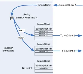
Figure 10. ioBroker Subscription Matching Process.
The real work behind the subscription process is done within the ioBroker. The
ioBroker examines the classID of every posted message,and then uses regular expressions
to compare the classID of every subscription entry of every brokerClient. If a match is
made, the ioBroker forwards the entire message to all matching brokerClients which, in
turn, forward the message to their connect iobClients. Upon receipt of a message from the
ioBroker, the iobClient examines the classID of the message and determines which
callback function to call (as specified by the 'callback' parameter of the subscribe
function). The callback function is then called with the 'data' parameter specified in the
subscribe function call.
2.3.3 brokerClient
The brokerClient is a software component that exists purely inside the ioBroker
iobClient connected through either a Unix Domain socket or a TCP/IP socket; as such,
the ioBroker maintains a collection of brokerClients, one for every connected iobClient.
When the ioBroker receives a message, it notifies all of the brokerClients. The
brokerClients proceed to compare the message's classID with the classID of each of their
subscribe regular expressions. Upon match, the brokerClient forwards the message to the
iobClient at the other end of the socket.
2.3.4 ioBroker
The ioBroker itself is a rather simplistic application. Upon execution, it reads a number of
configuration variables from a specified configuration file including: file name of local
Unix Domain Socket to create and local TCP/IP port on which to listen. It then opens the
specified file and port and listens for incoming messages.
When an incoming message is received from a new iobClient, the ioBroker
creates and assigns a new brokerClient to the iobClient. From this point forward,
messages that are received from the client are parsed and all of the brokerClients are
notified.
Initially, nothing is known about the data or exactly how many bytes are available
on the socket. The receiving iobClient assumes that at least 4 bytes are available and
proceeds to read them; if 4 bytes are not available, an error is signaled, otherwise, these 4
bytes are assumed to contain the length of the message to be received. The iobClient then
reads the correct number of bytes into a dynamically allocated buffer, signaling an error
2.4 ioBroker Details
2.4.1 ioBroker
2.4.1.1 Command Line Options
Before any other processing is done, the ioBroker parses the command line arguments
and stores all relevant data for use later in the startup process. The following are valid
command line arguments:
Option Parameter Description
-h --help none print help
-c --config path to
configuration file
read configuration from specified file
-b --broker path to broker socket
create the Unix socket at the specified path
-p --pid-file Path to PID file create the specified file that contains the PID of the ioBroker process
-d --no-detach none keep the ioBroker attached to the terminal and output text
Table 4. ioBroker Command Line Parameters.
2.4.1.2 Configuration File
The configuration file used for ioBroker and a number of other elements in the system is
a simple, hierarchal, plain-text file. A directive is considered a line of text that contains
an equality or an assignment such as:
foo = 14
Figure 11. Configuration File Example Directive.
Since the file is hierarchal, directives can be contained within path elements as
bar{ foo = 14 }
Figure 12. Configuration File Directive Hierarchy.
In this example, the directive path for foo is 'bar::foo' and 'foo' is a directive of type
integer.
If the '-c/--config' command line argument is provided to the ioBroker, it will
attempt to read the specified configuration file before any further processing is
performed. If no configuration file is specified, ioBroker looks for a configuration file at
the default path of "/opt/impact-tek/etc/ioBroker.conf". The following directives are valid
in the configuration file:
Directive Path Data Type Description
socket-path String path used to create the Unix socket (overridden by -b command line parameter)
log::module-pattern String a regular expression that determines which ioBroker modules output to the log
log::output-mask Integer a mask that determines what level of logging is output to the log
log::output-file String path to a logfile, or 'stdout'/'stderr'
tcp-port Integer which tcp port to listen for remote clients on
send-timeout-seconds Float how long the ioBroker should block on a send call
Table 5. ioBroker Configuration File Directives.
Now that the operation of the ioBroker architecture has been described, a closer look at
Chapter 3 - Extensions to ioBroker
When the ioBroker architecture was originally developed, it was purposed almost
exclusively for inter-process communication on a single computer. The ability of clients
to connect to an ioBroker running on a remote machine was included because it was
fairly easy to accomplish and would provide some interesting options for future
development. The inclusion of this rather simple feature served as the foundation for the
advancements of the ioBroker architecture.
3.1 Original iobClient Networking
As mentioned above, the original iobClient networking allowed for single iobClients to
connect to an ioBroker located on a remote computer. This allowed for a very
rudimentary multi-pc communication network similar to the one shown in Figure 13
below:
Figure 14. Duplicated traffic.
There are a number of limitations inherent in this scheme: All traffic must be
routed through a central ioBroker; in situations where there are more than two computers
this results in a duplication of network traffic as well as processing effort on the central
ioBroker computer, depicted in Figure 14. The central ioBroker also presents a single
point of failure for the entire system as shown in Figure 15. If the central ioBroker
unexpectedly terminates or its network connection becomes unavailable, the entire
system becomes unavailable.
Figure 15. Single point of failure.
iobClient. Not only does this increase the network traffic and processing effort on the
ioBroker, but also drastically increases the lag for communication between the two
processes running concurrently on a single machine.
3.2 New ioBroker Networking
The limitations of the original ioBroker networking capabilities, as well as the need for
additional functionality, make a very good case for the extensions presented. The goal of
these extensions is to provide an intuitive and efficient architecture for inter-process and
inter-computer communication. With this base functionality in place, the addition of
computer vision specializations becomes rather trivial.
3.2.1 Overall System Architecture
In this new architecture, instead of running a single, central ioBroker, there exists a
separate ioBroker for each computer in the system. Every iobClient therefore has an
ioBroker that is local to their respective computer and as such, can communicate with it
using Unix Sockets. TCP/IP iobClients in the new architecture are relegated to use on
orphaned computers, i.e., computers without an ioBroker, and should be avoided as much
as possible.
When each ioBroker first executes, it connects to all of the other ioBrokers
forming a fully connected mesh network. Each ioBroker not only keeps track of the
subscriptions of locally connected iobClients but is also responsible for ensuring that
messages of interest encountered by remote ioBrokers are also forwarded locally. This is
accomplished by a rather simplistic message routing algorithm detailed later. The routing
which they are subscribed, no matter where the message source or destination iobClient is
located within the overall network. The routing algorithm also provides such message
routing in a manner which ensures the least amount of the network traffic possible,
reducing both network load and latency.
Since all processes that are common to a single computer communicate locally
using Unix sockets and the local ioBroker, many of the limitations present in the original
ioBroker architecture are overcome. First, the amount of network traffic is significantly
reduced as messages between two local processes never enter the network to begin with.
Further, messages between two remote processes are forwarded intelligently producing a
minimum of required network traffic. Due to the reduced network traffic, and local
routing of inter-process messages, network/message latency is also reduced.
Finally, since there is no essential central ioBroker, and all of the ioBrokers
communicate using a fully connected network topology, there is no single point of
failure. If one ioBroker terminates, it is automatically removed from the mesh network,
and messages are forwarded as normal; granted any iobClients local to the terminated
ioBroker machine are unable to communicate, but the system as a whole remains
operational.
3.2.2 BrokerBridge Addition
The main backbone of the new ioBroker architecture is the addition of the BrokerBridge
object. This object is internal to the ioBroker and, thus, does not concern the end-user,
with the remote ioBrokers using the iobClient library. For each remote ioBroker, the
BrokerBridge maintains exactly one iobClient.
Figure 16. BrokerBridge Networking Architecture.
The functions performed by the BrokerBridge fall into two distinct categories:
constructing the ioBroker network, known as the ioBroker Discovery Process and routing
messages between ioBrokers.
3.2.3 Message Additions
In order to add the functionality detailed here, a number of 'Raw Messages' were added to
aid in ioBroker-to-ioBroker communication. 'Raw Messages' are messages that are passed
from iobClient to broker, the content of which the user sees, if at all, after manipulation
by the iobClient; in this particular case, the messages are not seen by the user at all.
3.2.3.1 BrokerAnnounce Message
The 'BrokerAnnounce' message is used by a newly initialized ioBroker to announce its
presence to the existing ioBroker network. The message itself contains information about
Figure 17. ioBroker ‘Announce’ message format.
Field Description
size size of the entire message in bytes
type Only ‘brokerAnnounce’
NULL NULL terminator
hostname Hostname of the announcing ioBroker
NULL NULL terminator
ip IP address of the announcing ioBroker
NULL NULL terminator
portNumber TCP/IP port number that the ioBroker is listening on
Table 6. ioBroker 'Announce' message fields.
As with the ‘post’, ‘subscribe’, and ‘unsubscribe’ ioBroker messages, the first
four bytes of the ‘brokerAnnounce’ message contains the number of bytes in the entire
message. The next field indicates the message type which, in this case, is a
brokerAnnounce message using a null-terminated string. Following the message type is
the hostname of the computer that the announcing ioBroker is running on, again,
null-terminated. The next field contains the IP address of the computer that the announcing
ioBroker is running on, in dotted-decimal ASCII format, null-terminated. The final field
contains the TCP/IP port number on which the ioBroker is listening.
3.2.3.2 BrokerResponse Message
about the IP address of the connected broker and is sent to an ioBroker that is attempting
to join the network.
Figure 18. ioBroker ‘brokerResponse’ message format.
Field Description
size size of the entire message in bytes
type Only ‘brokerResponse’
NULL NULL terminator
hostname Hostname of the announcing ioBroker
NULL NULL terminator
ip IP address of the announcing ioBroker
NULL NULL terminator
portNumber TCP/IP port number that the ioBroker is listening on
Table 7. ioBroker ‘brokerResponse’ message fields.
Essentially, the ‘brokerResponse’ message is identical to the ‘brokerAnnounce’
message, except for the type field containing the null-terminated string ‘brokerResponse’
instead of ‘brokerAnnounce’.
3.2.3.3 BrokerAnnounceProxy Message
The 'BrokerAnnounceProxy' message is used by the ioBroker hub to forward
'BrokerAnnounce' messages to all known ioBroker spokes. It contains the same
Figure 19. ioBroker ‘brokerAnnounceProxy’ message format.
Field Description
size size of the entire message in bytes
type Only ‘brokerResponse’
NULL NULL terminator
hostname Hostname of the announcing ioBroker
NULL NULL terminator
ip IP address of the announcing ioBroker
NULL NULL terminator
portNumber TCP/IP port number that the ioBroker is listening on
Table 8. ioBroker ‘brokerAnnounceProxy’ message fields.
Again, this message is nearly identical to the above two message types, except for
the type field. In this case, the type field contains ‘brokerResponse’ in a null-terminated
string.
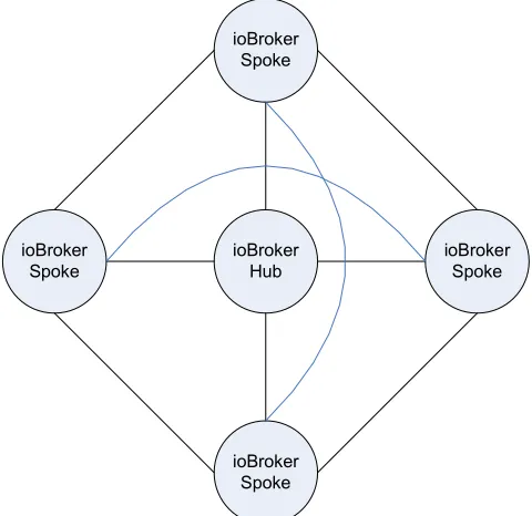
3.2.4 ioBroker Discovery Process
The ioBroker Discovery Process refers to the initial communication sequence that builds
the mesh network of ioBrokers. To begin with, there are now two different types of
ioBrokers: Spokes and Hubs. In any single network, only one ioBroker is the hub, the rest
are spokes. When connected, the hub and spoke ioBrokers generate a fully-connected
ioBroker Hub ioBroker
Spoke
ioBroker Spoke
ioBroker Spoke ioBroker
Spoke
Figure 20. Mesh/Star ioBroker Network.
3.2.4.1 Hub ioBrokers
The hub ioBroker is a singleton entity within the ioBroker network. The ioBroker that
will serve as the hub is determined by the network designer at run-time through the
aforementioned ioBroker configuration file. The new ioBroker configuration file for hubs
adds the following field:
Directive Path Data Type Description
[image:41.612.186.426.74.307.2]bridge:: String Empty field
Table 9. New ioBroker Configuration File Fields.
As can be seen in Table 9, the only addition is the empty bridge path. While there
are configuration directives that will be present within this path for the spoke ioBrokers,
the absence of any indicate that an ioBroker should operate in hub mode.
In hub mode, the ioBroker initializes in a manner very similar to the original
Socket for locally connected clients and on a specified TCP/IP port for connections from
spoke ioBrokers.
3.2.4.2 Spoke ioBrokers
Unlike hub ioBrokers an ioBroker network can contain a large number of spoke
ioBrokers. These spoke ioBrokers are specified at run-time again through the use of the
ioBroker configuration file. The new ioBroker configuration file for spokes adds the
following fields:
Directive Path Data Type Description
bridge::remote-broker String IP address of the ioBroker Hub
Table 10. Added ioBroker configuration file fields.
As can be seen in Table 10, in addition to the bridge path, the ioBroker spoke
configuration file includes the 'remote-broker' directive. This directive is used to specify
the hostname or IP address of the hub ioBroker. In spoke mode, initialization requires
that the hub ioBroker be running and reachable over the network; note that this limitation
is only during initialization.
3.2.4.3 Network Initialization
Since the spoke ioBrokers require that the hub ioBroker be both running and reachable,
the network initialization begins by starting the hub ioBroker. Once the hub ioBroker has
initialized, each of the spoke ioBrokers can then be started. When a spoke ioBroker
initializes, it creates its BrokerBridge object and adds a single iobClient to an internal list
lets the hub know that a spoke ioBroker has connected to it, and at what remote IP and
port number the spoke is located.
The hub ioBroker receives the announcement message and creates a new
iobClient within its BrokerBridge array. The hub uses this iobClient to connect to the
new spoke ioBroker. Once this connection is complete, the hub responds to the spoke
with a 'BrokerResponse' message containing the IP and port number of the ioBroker hub.
The spoke iterates through its BrokerBridge array of iobClients looking for a match of IP
and portnumber. If a match is made, the connection to the hub ioBroker is considered
complete and ready for two-way communication.
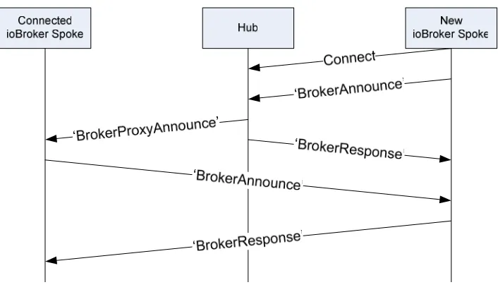
Figure 21. Spoke-Hub Connection Sequence.
In addition to creating a two-way connection with the new spoke ioBroker, the
ioBroker hub passes the information contained within the initial 'BrokerAnnounce'
message to all other known spoke ioBrokers using a 'BrokerAnnounceProxy' message.
Upon receipt of the 'BrokerAnnounceProxy' message, a spoke ioBroker creates a new
iobClient within its BrokerBridge and connects to the IP address and port number
specified in the 'BrokerAnnounceProxy' message. Upon successful connection, the
remote spoke ioBroker sends a 'BrokerAnnounce' message to the first spoke ioBroker
an iobClient to its BrokerBridge and connects to the remote spoke ioBroker. The first
spoke then responds with a 'BrokerResponse' message to the remote spoke which
contains the first spoke's IP address and port number. Upon receipt of the
'BrokerResponse' message, the remote spoke iterates through its BrokerBridge array of
iobClients looking for a match of IP and port number. If a match is made, the connection
between the two spoke ioBrokers is considered complete and ready for two-way
[image:44.612.130.483.267.474.2]communication.
Figure 22. Spoke-Spoke Connection Sequence.
Since the ioBroker hub forwarded the 'BrokerAnnounceProxy' message to all
known spoke ioBrokers, the above process repeats for each known spoke ioBroker
creating a fully-connected mesh network.
3.2.5 Message Routing
Since the network used for ioBroker communication is fully-connected, for
ioBroker local to the destination client. This path results in a minimum of network traffic
and eliminates the need for any complex routing algorithms.
Since the ioBroker architecture works on a post/subscribe model, all
communication must be prefaced by a subscription request posted by the destination
iobClient. Naturally, the subscription request is posted to and processed by the locally
connected ioBroker. Under the original ioBroker architecture, the central ioBroker is
privy to all messages being sent because it is directly connected to all iobClients. In the
new architecture, each ioBroker is only connected to a small subset of the iobClients in
the network; therefore, there must be a method to forward messages between two
ioBrokers.
One method would be to simply forward all messages received locally to the
remote ioBrokers. The problem with this method is that it generates a considerable
amount of unnecessary network traffic as it is extremely unlikely that every message
must be received by an iobClient on every remote ioBroker.
The second and more efficient method is to only forward messages to remote
ioBrokers that have a local iobClient subscribed to that message classID. This method is
termed a “ProxySubscribe”. In this method, when a iobClient subscribes to a classID
using its local ioBroker, the local ioBroker uses its iobClients stored within BrokerBridge
to subscribe to that classID on the remote brokers. When a message with the matching
classID is posted by an iobClient on a remote ioBroker, the remote ioBroker goes through
its list of brokerClients as usual looking for matching classIDs. Since the brokerClient of
message is passed to the iobClient of the local ioBroker's brokerBridge. Upon reception
the iobClient posts the message to the local ioBroker like normal.
Figure 23. Remote Subscription Sequence.
One problem with this method is that it is prone to routing loops due to the fully
connected nature of the ioBroker network. Take, for instance, the case with two
ioBrokers, ioBroker-A and ioBroker-B, ioBroker-A with one client and ioBroker-B with
two clients. On ioBroker-A, client one is subscribed to the classID of “test”,
consequentially, the iobClient of ioBroker-A's brokerBridge is also subscribed to “test”
on ioBroker-B. On ioBroker-B, client two is subscribed to the classID of “test” as well,
and again, consequentially the iobClient of ioBroker-B's brokerBridge is also subscribed
to “test.
In this case, the local brokerClient for the locally connected client two matches, and the
message is sent. In addition, the brokerClient for the iobClient of ioBroker-A's
brokerBridge also matches and the message is forwarded as well; this is where the
problem starts.
Figure 25. First step in potential routing loop.
When the iobClient of ioBroker-A's brokerBridge receives the message, it posts it
to ioBroker-A as a normal message. Then, ioBroker-A iterates through its list of
brokerClients and sees a match with the locally connected iobClient of Client 1, however,
it also sees a match with the brokerClient of ioBroker-B's brokerBridge. Consequentially,
Figure 26. Completion of potential routing loop.
The solution to this problem is to only allow ioBroker-A to post the message
received from ioBroker-B to brokerClients of locally connected ioBrokers. With this
limitation, ioBroker-A cannot post the message to the brokerClient of ioBroker-B,
breaking the loop, but still allowing the required message forwarding to occur.
Figure 27. Avoidance of routing loop.
3.3 iobSession Layer
data between processes utilizing the ioBroker architecture. These goals are met in three
distinct ways: by encapsulating an iobClient reducing the programming overhead of
initialization and connection, by the introduction of standardized classID naming
conventions, and by the creation of two message formats that can be encapsulated within
an existing iobMessage.
Figure 28. iobSessionLayer hierarchy.
3.3.1 iobSessionLayer Internal Organization
The iobClient was initially designed with ease of use in mind. In addition it is extremely
flexible from a programmatic point of view. Ease of initialization and connection is one
instance where the latter point of view won out at the detriment of the former. In order to
initialize an iobClient, the programmer must provide not only information about the
location of the ioBroker, they must also provide an iobWait object as well as thread to
process incoming requests. The iobSessionLayer incorporates not only an iobClient, but
all of the objects necessary for the iobClient to function, eliminating any external
Figure 29. Internal Structure of iobSessionLayer object.
3.3.2 classID Naming Conventions
The classIDs of the ioBroker architecture are simply null-terminated ASCII strings.
While this provides the programmer or system designer with a virtually unlimited palate
for orchestrating inter-process communication, it becomes a significant design burden
when working with even a system of medium complexity. In this case, the classID
structure must be carefully laid out to provide distinctions between similar processes
running on different computers, different message types output by a single process, and
messages bound for single or multiple destinations. The classID naming conventions
have been extracted from patterns in naming conventions that have arisen in other
projects, and provide significant functionality and flexibility.
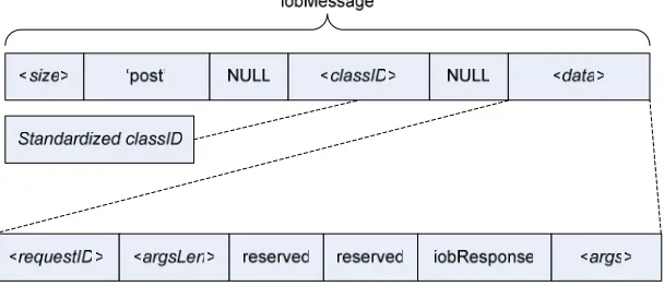
3.3.2.1 classID format
Figure 30. Standardized classID format.
srcComp: The srcComp field is a string that contains the hostname of message's origin
computer. This field allows the programmer or designer to subscribe to messages based
srcMod: The srcMod field is a string that describes the module that sent the message.
This string is specified during the initialization of the iobSessionLayer object and is
commonly referred to as the modules name. The inclusion of this field allows the
programmer to subscribe to all messages generated by a set of particular algorithms
running on one or multiple computers.
dstComp and dstMod: Like the srcComp and srcMod fields, the dstComp and dstMod
fields specify the hostname of the message's destination computer and the name of the
destination process respectively. These fields are primarily used in systems where
point-to-point communication between algorithms on separate computers is required. Due to
the regular expression, subscription-based nature of ioBroker, it should be noted that
these fields do not guarantee that the message will only be received by the destination
computer or process. However these fields do provide convenience functionality for
systems making proper use of the iobSessionLayer.
type: The type field is a string that describes the type of message that the classID is
accompanying. This field is controlled by the iobSession layer based upon the functions
or methods used to send the message and can be 'RPC-REQUEST', 'RPC-RESPONSE',
or 'DATAGRAM', all of which are detailed in the following section.
desc: Finally, the desc field is a user-controlled descriptor that describes the actual
content of the message. This field is generally used to distinguish between two distinct
messages types sent by or received by a single process. For example, one process may
produce two different types of RPC requests, both destined for the same module and
computer; the descriptor field provides a way for the receiving process to separate the
3.3.3 Datagram Messages
The datagram message, denoted by 'DATAGRAM' in the type field of a
iobSessionLayerMessage is essentially an iobMessage with a standardized classID. The
message itself simply contains a chunk of raw data that is controlled directly by the user.
Figure 31. Datagram message structure.
3.3.4 Remote Procedure Calls
Remote procedure call (RPC) functionality is added to the iobSessionLayer using
'RPC-REQUEST' and 'RPC-RESPONSE' messages. The purpose of RPCs is to provide a
consensual, standardized mechanism for a process to initiate or control execution of a
remote process. Again, these messages use an iobMessage for communication, using a
standardized classID, and in this case, a preset message structure.
3.3.4.1 Registering an RPC
To initiate a RPC, the process that will be performing the procedure, known as the
registered process, must first tell the iobSessionLayer that it is willing to provide RPC
functionality. This is accomplished by registering the function within the
3.3.4.2 Executing an RPC
To execute an RPC function, there is a comparatively large amount of data required by
the iobSessionLayer. The first set of required information are the hostname, module
name, and function name of the registered RPC function. This set of information allows
the iobSessionLayer to craft a standardized classID that can be routed directly to the
registered function.
The second set of required information specifies what the calling process should
do while waiting for a response. A zero (0) indicates that the process should not wait for a
response and should immediately continue execution. Numbers greater than zero indicate
that the process should wait for the indicated number of milliseconds for a response from
the registered process, while a one (1) indicates that the process should wait indefinitely.
The inclusion of these parameters allow the designer or programmer to differentiate
between best-effort method calls that do not return any data, and functions that do return
data, and hence, an indication of success or failure.
The third set of required information allows the programmer to pass arbitrary
parameters to the function. The arbitrary parameters are required to be contained within a
contiguous block of memory, and it is assumed that by initiating an RPC, the programmer
knows the format and number of arguments expected by the function. Finally, the last set
of required information allows the programmer to obtain a return value from the RPC.
Like the parameters mentioned above, a return value is not required, and simply returns a
contiguous block of memory. It is assumed that the size and format of the returned
Using this information, the iobSessionLayer generates an RPC Request message
encapsulated within an iobMsg, which is then sent using the encapsulated iobClient
object. The request is then added to an internal list of active RPC requests maintained by
the local iobSession object. If requested, the iobSessionLayer will now wait until a
response is received from the registered RPC process. If no response is received within
the specified time frame, the request is removed from the RPC request list, and
iobSessionLayer returns with an error indicating a timeout has occurred.
If, however, the message is properly routed through the ioBroker and received by
the proper iobSessionLayer object in the proper process, known as the remote
iobSessionLayer, RPC execution begins. The remote iobSessionLayer executes the
registered function, passing it the block of memory indicated by the local
iobSessionLayer as parameters. Execution continues until the function is complete, at
which point the RPC function returns a block of data containing the return value of the
function. The remote iobSession layer encapsulates the return value and initial requestID
into an RPC Response message, and that message returned to the local iobSessionLayer
through the ioBroker.
When the local
![Figure 2. Proposed MASCOT System Architecture [7],[8].](https://thumb-us.123doks.com/thumbv2/123dok_us/55252.5075/15.612.166.448.70.390/figure-proposed-mascot-system-architecture.webp)