Baker, P.C. and Stephen, B. and Judd, M.D. and McArthur, S.D.J. (2009) Development of an integrated
low-power RF partial discharge detector. In: Electrical Insulation Conference, June 2009, Montreal, Canada.
http://strathprints.strath.ac.uk/
27659
/
Strathprints is designed to allow users to access the research output of the University of
Strathclyde. Copyright © and Moral Rights for the papers on this site are retained by the
individual authors and/or other copyright owners. You may not engage in further
distribution of the material for any profitmaking activities or any commercial gain. You
may freely distribute both the url (
http://strathprints.strath.ac.uk
) and the content of this
paper for research or study, educational, or not-for-profit purposes without prior
permission or charge. You may freely distribute the url (
http://strathprints.strath.ac.uk
)
of the Strathprints website.
Development of an Integrated Low-Power RF Partial
Discharge Detector
P. C. Baker *, B. Stephen, M. D. Judd, S. D. J. McArthur Institute for Energy and Environment
University of Strathclyde 204 George Street Glasgow, G1 1XW UK
*Corresponding author email: [email protected]
Abstract- This paper presents the results from integrating a
low-power partial discharge detector with a wireless sensor node designed for operating as part of an IEEE 802.15.4 sensor network, and applying an on-line classifier capable of classifying partial discharges in real-time.
Such a system is of benefit to monitoring engineers as it provides a means to exploit the RF technique using a low-cost device while circumventing the need for any additional cabling associated with new condition monitoring systems.
The detector uses a frequency-based technique to differentiate between multiple defects, and has been integrated with a SunSPOT wireless sensor node hosting an agent-based monitoring platform, which includes a data capture agent and rule induction agent trained using experimental data. The results of laboratory system verification are discussed, and the requirements for a fully robust and flexible system are outlined.
Index Terms-- Partial discharges, UHF measurements,
substations, monitoring, wireless sensor networks, multi-agent systems, decision support systems.
I. INTRODUCTION
Partial discharge (PDs) monitoring has been proven as an invaluable tool in determining the state of electrical plant, which, due to regulatory and financial constraints on electricity utilities has become an area receiving significant research in recent years.
Partial discharges arise when a breakdown in the dielectric insulation occurs within electrical plant, and can indicate the presence of faults long before equipment failure occurs. A number of established detection techniques have been developed, such as IEC60270, RF and acoustic, as well as a number of different analysis techniques.
This paper discusses the embedded software and hardware architecture for a battery-operated partial discharge detector based upon the RF method [1], which uses a frequency-based technique to detect partial discharge emissions. The platform is based around a SunSPOT wireless sensor node [2] that captures the spectral energies of RF PD emissions in different bands and is able to classify them using a decision tree generated from the C4.5 algorithm.
CIGRE has recently published a report outlining facilities for power transformer CM systems [3], recommending that the level of condition monitoring applied to plant should be based upon asset value. A low-cost PD detector would allow
RF monitoring to be economically viable on lower-valued assets where the RF technique would not otherwise be considered. Such a system is intended for use as part of a larger condition monitoring sensor network, which would consist of multiple low-power wireless sensors.
II. BACKGROUND
A. Partial Discharge Monitoring
Previous RF PD monitoring techniques have applied wideband signal processing to recorded signals to establish both defect type and defect location [4]. This approach has successfully been applied to a number of plant items such as transformers [5], GIS [6] and HVDC reactors [7], which have been known to have defects present, identifying defect type and location while the plant item is still online. This approach does have certain drawbacks, as it cannot be economically deployed across large numbers of plant and wideband sampling cannot be carried out on low-power, low-cost hardware as the signal processing capabilities required are too resource intensive.
Contin et al. [8] have stated that conventional PD pulse measurement equipment ignores the frequency content of recorded signals, which may be useful for classification. The use of frequency content for classification of wideband PD signals has previously been demonstrated [9]. By using a frequency-based method with low power hardware, it is possible to take advantage of the RF technique without the need for wideband signal capture and its associated overheads.
C. Wireless Sensor Networks
Wireless sensor networks offer significant advantages over wired equivalents. Firstly, wireless sensors do not require costly and potentially hazardous cabling throughout a substation. Secondly, by analysing monitoring data at the source and only transmitting pertinent information, bandwidth requirements can be reduced to a manageable level, thus reducing the need for expensive high-capacity communication links between substations and corporate networks.
D. Multi-Agent Systems
The accepted definition of an intelligent agent within the Power Engineering community is that of Wooldridge, which states that an agent must be: reactive, taking action based upon changes in its environment; pro-active, carrying out goal-oriented behavior and; socially able, with the ability to cooperatively interact with other agents. A multi-agent system is defined as a software system consisting of two or more intelligent agents.
Multi-agent systems (MAS) have been used extensively for power engineering applications, in areas including monitoring and diagnostics, protection, distributed control, and modelling and simulation [14]. Multi-agent systems have successfully been applied at the substation level [15], but as the need for effective condition monitoring systems increases, the need for intelligent monitoring techniques at the sensor level increases also. By deploying software agents on embedded hardware, data is processed at the source, which not only increases the speed at which useful CM information can be generated, but also reduces communications bandwidth associated with the transmission of large amounts of raw data [16].
MAS technology itself does not provide reasoning capabilities for intelligent agents, but instead provides a platform on which to integrate intelligent techniques that can be used for data analysis and decision-making. Classification of data can be carried out using a number of different methods: for the application discussed here, rule induction was chosen as a suitable technique.
E. Rule Induction
Classification problems are often presented without the form of the classes being known a-priori – the shape and location of a decision boundary between one class and another may be complex and lie outside the problem domain knowledge. If a set of representative data is available which contains observations that are labelled according to the class they belong to, then a supervised learning technique could be used to find the class specific decision surface from this data. One such technique is Rule Induction, which takes such a set of labelled exemplar data and produces decision rules that partition the observation space and in doing so describe the classes in terms of the range of values that their associated observations take. Although there are many rule induction techniques that offer trade-offs on inference speed,
scalability and error rates, one enduring implementation is C4.5 [17].
C4.5 uses the information content of case data to partition the observations hierarchically, producing a decision tree which branches at particular observation values and terminate in leaf nodes when a classification is made. Once learned, a decision tree can be converted into a set of rules by traversing the path from the root to every leaf, which produces an initial set of rules, then removing the antecedents that offer little or no classification accuracy. During this process, duplicate rules will arise as their distinct lists of antecedents are reduced – these are deleted to leave a compact set of classification rules. Aside from providing automatic classifications, as an alternate technique such as a Neural Network might do, rules produced by C4.5 resemble the human decision making process and classification are hence readable and deterministic.
III. DETECTOR OVERVIEW
A. System Overview
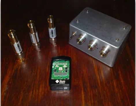
The low-power partial discharge detector (see Figure 1) employs a frequency-based technique, capturing the relative spectral energies of an RF PD pulse across 3 frequency bands (see Figure 2). An RF detector on each channel responds to the pulse envelope of the signal, which is then captured by peak-hold circuitry to be sampled by an analog-to-digital converter.
The detector is connected to a Sun Microsystems SunSPOT wireless sensor node, which consists of a 180MHz ARM processor, 512KB RAM and 4MB flash memory. The device runs an embedded version of the Java programming language.
The PD detector is triggered once the voltage on one of its channels reaches the detection threshold voltage. Upon triggering, the sensor node samples each of the detector channels, and then activates the reset circuit with a pulse, which switches each of the peak-held spectral energy
[image:3.595.314.550.531.716.2]voltages to ground. This in turn resets the detector trigger. The detector acquisition window is the time between detector triggering and the falling edge of the reset pulse. This is the minimum time between PD pulses that the detector can successfully discriminate.
B. Decision Tree Training
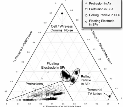
Four high-voltage PD test cells were used to generate the test data, which simulate the following defects: floating electrode in SF6, rolling particle in SF6, protrusion in SF6,
and protrusion in air. The defects were connected to a 15 kV transformer, and energized at a voltage just above PD inception. Results, which can be seen in Figure 3, were captured using a 1 Gsample/s oscilloscope. Data was collected for each test cell in two different positions, which had a noticeable effect on the observed spectra, suggesting that frequency content is in part a function of tank geometry. However, the dominant factor dictating frequency content can be seen to be the type of PD source.
The C4.5 algorithm was chosen for the application as the frequency components of each defect type were seen to be directly linearly separable. The training process used 50% of the test data for training and 50% for validation, with a 1.1%
error rate. Upon completion of training, a binary decision tree and rules file is created, which can be loaded and executed by a suitable decision tree engine.
IV. DETECTOR SOFTWARE ARCHITECTURE
A. Platform Overview
The software system consists of a multi-agent system platform developed specifically for the SunSPOT platform, hosting a number of software agents for data capture and classification, as seen in Figure 4. The agent system has been designed to be generic, providing a number of prototype agents and behaviors on which to base applications. It is extensible and may be used with any suitable sensor type or analysis method. The agent container includes two system agents: the System Management agent, which controls inter-node communication and power management, and the Directory Agent, which provides a lookup service for agent services.
Two application agents are used for this application, although the system can accept new agents, even at runtime if necessary. The application agents are described as follows.
B. Data Capture Agent
[image:4.595.58.299.89.178.2]The data capture agent provides a standard interface to the PD detector, receiving sample vectors each time a PD pulse is detected. The underlying driver is configured to reset the detector each time a PD has been captured, readying it to receive the next sample. Upon receiving a new sample, it is stored within the agent datastore, at which point it is forwarded to the C4.5 classifier agent for classification. Depending on the configured behavior of the agent, at this point the PD sample could be archived to allow classification to be applied in batches. The SunSPOT device has 4 MB of flash memory, so if necessary, the order of millions of data points may be stored on the device.
Figure 3. Ternary plot showing results from laboratory case study. Defect types and other known regions have been highlighted. Plotting in this fashion is possible by converting the 3-dimensional frequency component data into a 2-dimensional simplex by converting to proportional form.
Figure 2. PD detector block diagram. The raw PD signal is split into 3 frequency bands which are captured by the sensor node. This is then converted to proportional form for analysis.
[image:4.595.49.289.497.705.2] [image:4.595.312.545.526.708.2]C. C4.5 Classifier Agent
Partial discharge classification is carried out by a C4.5 classifier agent. Upon agent instantiation, the decision tree is loaded from flash memory, and is ready to start receiving PD sample data for classification. The platform supports the transmission of decision trees remotely, allowing for the rule induction model to be updated, for instance of the decision tree has been refined from the addition of new training data.
Once the decision tree has been loaded, a Partial Discharge Classifier service is registered on the local node, which accepts PD samples for classification. The capture agent is notified of this event, and starts sending partial discharge samples to the classifier agent for analysis. Upon receiving each sample, the data is classified and a new classification result is generated.
V. LABORATORY TESTING AND DISCUSSION
The laboratory test was carried out using the same equipment used for the detector development. The aims of the test were to establish: (i) the functionality and accuracy of the integrated detector, and; (ii) any hardware or software optimizations required for proper operation.
A 'rolling particle in SF6' test cell was placed in an
enclosed aluminium test tank. The cell was energized at 10 kV using the HV transformer. The PD detector was attached to a ‘disc coupler’ UHF sensor mounted on one wall of the test tank.
Initial results showed that the software system works as expected, with the software agents successfully capturing and classifying PD emissions. However, the results did not immediately correlate with the data captured previously, which was found to be due to the operation of the detector acquisition process. Analysis of the experimental data has led to a number of proposed optimizations to the detector, which are described as follows.
A. Detector Input Gating
The detector acquisition window is fundamental to the proper functioning of the detector. An example signal trace can be seen in Figure 5, which shows a pair of consecutive PD pulses and the detector trigger and reset signals. The acquisition time, ta, is shown to be before the second PD,
although if a PD were to occur within the acquisition window, the captured PD signals could be superimposed, producing a spurious sensor reading.
During testing, consecutive PDs were occasionally overlapping in the detector, causing invalid data to be captured. It is therefore necessary for the detector inputs to be disabled as soon as a PD has been detected. An input enable gate is proposed to avoid collisions, ensuring that PDs that occur within the acquisition window of a previous PD emission are ignored. The detector inputs should be disabled at the rising edge of the sample trigger, and re-enabled at the falling edge of the reset pulse.
B. Acquisition Window Optimization
The acquisition window encapsulates a number of chained events, each with an associated time period: 1) RF signal detection, peak-hold and trigger activation, which is governed by the physical detector hardware; 2) signal sampling, and; 3) reset pulse generation, which are both carried out by the PD detector driver. The acquisition window ends at the falling edge of the reset pulse.
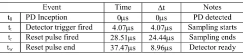
Even if the detector inputs are disabled, pulses occurring during the acquisition time will be ignored, so this period must be minimized to allow the maximum number of PD events to be captured. The events occurring within the acquisition window were therefore investigated to determine the scope of optimization. The mean times for each event were captured for 500 PDs, which can be seen in Table 1 below.
TABLE I
MEAN ACQUISITION WINDOW EVENT TIMES, RELATIVE TO PD INCEPTION
Event Time ∆t Notes
t0 PD Inception 0µs 0µs PD detected
tt Detector trigger fired 4.07µs 4.07µs Sampling starts
tr Reset pulse fired 28.51µs 24.44µs Sampling ends
tw Reset pulse end 37.47µs 8.96µs Detector ready
The detector trigger time, tt, is dependent on the physical
detector circuit so cannot be readily optimized. The largest segment of acquisition time is associated with sampling, which is governed by the PD detector driver software. Therefore, the software must be optimized to ensure that the reset pulse is generated as soon as data is captured.
The reset pulse width was set to the minimum supported by the SunSPOT pulse width modulation circuit (PWM), which was measured as 8.96 µs. It was found that, for large PD, this pulse was not always long enough to permit complete resetting of the peak-hold circuitry. This process is governed by the time constant of the reset circuit, which also needs to undergo optimization through software simulation.
As the pulse width is at the physical minimum for the SunSPOT device, it is also necessary to create an adaptive algorithm that generates a reset pulse proportional to the PD magnitude. This would work in tandem with the input enable gate, so the acquisition window would be proportional to magnitude of PD captured.
[image:5.595.313.553.452.507.2]The optimizations that have been outlined will make the PD detector more robust, reducing the possibility for error and enabling the system to adapt to different PD magnitudes. This will ensure that the detector is suitably robust for field trials.
VI. CONCLUSIONS AND FUTURE WORK
This paper has presented the results of validating an integrated low-power partial discharge detector for use within a condition monitoring sensor network. The system has used a multi-agent system approach to ensure flexibility and extensibility, and consists of two agents for data capture and classification. A decision tree generated by the C4.5 algorithm has been generated, and tested within a laboratory environment. The system has been tested in a laboratory, and initial results have highlighted a number of opportunities for optimization within the physical detector and low-level software that will make the detector more robust and adaptable to different types of PD.
Future work will involve the application of all the changes discussed in this paper, followed by integration with a wider range of sensor types and an online server-based multi-agent system that is currently deployed in a substation field trial. Possible integration of an electromagnetic energy harvesting device is also being investigated, to allow the detector to operate in the substation environment in a fully autonomous manner, free of the practical constraints imposed by cabling and batteries.
ACKNOWLEDGMENT
This work is funded through the EPSRC Supergen V, UK Energy Infrastructure (AMPerES) grant in collaboration with UK electricity network operators working under Ofgem's Innovation Funding Incentive scheme; - full details on http://www.supergen-amperes.org
REFERENCES
[1] P. C. Baker, S. D. J. McArthur, and M. Judd, “A Novel Low-Power Frequency-Based UHF Partial Discharge Detector for Wireless Sensor Networking,” Submitted to IEEE Transactions on Dielectrics and Insulation, Nov. 2008.
[2] “Sun Microsystems SunSPOT,” 2007. [Online]. Available: https://www.sunspotworld.com/
[3] P. Jarman, “Recommendations for condition monitoring and condition assessment facilities for transformers,” CIGRE (Paris), Tech. Rep. Brochure 343, April 2008.
[4] M. D. Judd, L. Yang, and I. B. B. Hunter, “Partial Discharge Monitoring for Power Transformers using UHF Sensors Part 1: Sensors and Signal interpretation,” IEEE Electrical Insulation Magazine, vol. 21, no. 2, pp. 5–14, March 2005.
[5] M. D. Judd, G. P. Cleary, and C. J. Bennoch, “Applying UHF Partial Discharge Detection to Power Transformers,” IEEE Power EngineeringReview, Aug. 2002.
[6] J. S. Pearson, O. Farish, B. F. Hampton, M. D. Judd, D. Templeton, B. M. Pryor, and I. M. Welsh, “Partial Discharge Diagnostics for Gas insulated Substations,” IEEE Transactions on Dielectrics and Electrical Insulation,vol. 2, no. 5, pp. 893–905, Oct. 1995.
[7] M. D. Judd, S. D. J. McArthur, A. J. Reid, V. M. Catterson, L. Yang,
B. Jacobson, K. O. Svensson, and M. Gunnarsson, “Investigation of Radiometric Partial Discharge Detection for use in Switched HVDC
Testing,” Power Engineering Society General Meeting, 2006. IEEE, Jun. 2006.
[8] A. Contin, A. Cavallini, G. Montanari, G. Pasini, and F. Puletti, “Digital detection and fuzzy classification of partial discharge signals,” Dielectrics and Electrical Insulation, IEEE Transactions, vol. 9, no. 3, pp. 335–348, 2002.
[9] S. Meijer, “Partial discharge diagnosis of high-voltage gas-insulated systems,” Ph.D. dissertation, Technische Universiteit Delft, November 2001.
[10] K. Godrich, “Wireless integrated network sensors (WINS) implementation in substation automation (SA),” Power Engineering Society General Meeting, 2004. IEEE, p. 1043, 2004.
[11] W. H. Siew, Y. C. Liu, B. Musa, F. Mir, and Y. Wang, “Basis for a Wireless Network for EMC Measurements in electric Substations,” Electromagnetic Compatibility, 2007. EMC 2007. IEEE International Symposium on, pp. 1–5, July 2007.
[12] A. Nasipuri, R. Cox, H. Alasti, L. Van der Zel, B. Rodriguez, R. McKosky, and J. A. Graziano, “Wireless sensor network for substation monitoring: design and deployment,” in Proceedings of the 6th ACM conference on Embedded network sensor systems. ACM New York, NY, USA, 2008, pp. 365–366.
[13] Q. Gao and H. Wang, “WSN design in high-voltage transformer substation,” Intelligent Control and Automation, 2008. WCICA 2008. 7th WorldCongress on, pp. 6720–6724, Jun. 2008.
[14] S. McArthur, E. M. Davidson, V. M. Catterson, L. Dimeas, D. Hatziargyriou, F. Ponci, and T. Funabashi, “Multi-Agent Systems for Power Engineering Applications Part I: Concepts, Approaches, and Technical Challenges,” Power Systems, IEEE Transactions on, vol. 22, no. 4, pp. 1743–1752, 2007.
[15] V. Catterson, S. McArthur, M. Judd, and A. Zaher, “Managing remote online partial discharge data,” Power Delivery, IEEE Transactions on, vol. 23, no. 4, pp. 1754–1762, Oct. 2008.
[16] P. Baker, S. D. J. McArthur, and M. D. Judd, “Data Management of On-Line Partial Discharge Monitoring Using Wireless Sensor Nodes Integrated with a Multi-Agent System,” Intelligent Systems Applications to Power Systems, 2007. ISAP 2007. International Conference on, pp. 1–6, 2007.