Benchmarking and optimisation of Simulink code
using Real-Time Workshop and Embedded Coder
for inverter and microgrid control applications
A. J. RoscoeUniversity of Strathclyde [email protected]
S. M. Blair University of Strathclyde [email protected]
G. M. Burt University of
Strathclyde [email protected]
Abstract- When creating software for a new power systems control or protection device, the use of auto-generated C code via MATLAB Simulink Real-Time Workshop and Embedded Coder toolboxes can be a sensible alternative to hand written C code. This approach offers the benefits of a simulation environment, platform independence and robust code. This paper briefly summarises recent experiences with this coding process including the pros and cons of such an approach. Extensive benchmarking activities are presented, together with descriptions of simple (but non-obvious) optimisations made as a result of the benchmarking. Examples include replacement of certain Simulink blocks with seemingly more complex blocks which execute faster. “S functions” are also designed for certain key algorithms. These must be fully “in-lined” to obtain the best speed performance. Together, these optimisations can lead to an increase in execution speed of more than 1.4x in a large piece of auto-generated C code. An example is presented, which carries out Fourier analysis of 3 signals at a common (variable) frequency. The overall speed improvement relative to the baseline is 2.3x, of which more than 1.4x is due to non-obvious improvements resulting from benchmarking activities. Such execution speed improvements allow higher frame rates or larger algorithms within inverters, drives, protection and control applications.
Index Terms— Power system measurements, Power system control, Power system protection, Motor drives, Inverters, Power electronics
I. INTRODUCTION
When creating software for a new power systems control or protection device, the use of MATLAB Real Time Workshop and Embedded Coder toolboxes can be a sensible alternative to hand written C code [1-3]. First, this approach allows easy verification and test of the software before deployment on the target platform, by embedding the Simulink code in a simulation environment. Additionally, this approach provides platform independence because the Simulink code can be ported (normally without modification) to different platforms simply by use of the appropriate Embedded Coder plug-in. The use of Simulink also aids the production of robust code compared to methods such as hand written C code; this is particularly true for relatively inexperienced C programmers.
The authors have used this development process to aid in the creation of two significant real time software projects on two different platforms. The first project is a 10kVA 3 phase inverter control algorithm using the Infineon TC1796 microcontroller [4, 5]. The second project is a 100kVA
microgrid control application, using the multi processor ADI RTS MVME platform [6]. This paper summarises recent experiences with this coding process, including the pros and cons of such an approach.
II. BENCHMARKING
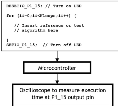
[image:1.595.308.499.320.492.2]To evaluate the performance of C code auto-generated by Real-Time-Workshop, a simple benchmarking environment has been created (Fig. 1), using the TC1796 microcontroller.
Fig. 1. Benchmarking environment using the TC1796 microcontroller.
Test algorithms, from the simplest code blocks to large program segments, are executed repeatedly within a for…next loop. The frame time is fixed at 1000µs and the number of iterations is set so that the execution takes most of this time. The execution time can be measured by setting logic transitions of a suitable output pin at the beginning and end of the for…next loop. Care must be taken to first run a reference case with an empty (or nearly empty) loop, to account for the overhead of the for…next loop and any associated code required to feed dummy data into the algorithm under test. This dummy data should not be fixed, but should change each iteration to cover the representative range of values expected to be input to each function. A similar environment has also been created on the RTS platform, although this is currently only suitable for measuring larger functions with execution times of many µs.
Oscilloscope to measure execution time at P1_15 output pin
RESETIO_P1_15; // Turn on LED
for (ii=0;ii<Nloops;ii++) {
// Insert reference or test // algorithm here
}
SETIO_P1_15; // Turn off LED
0.07 0.12
0.07 0.12
0.16 0.22
0.63 0.53
0.06
1.04
1.63 1.47
0.78
1.61
0.00 0.50 1.00 1.50 2.00 2.50
Simulink : Floating point increment/decrement/bias/unary minus
Simulink : Floating point addition/subtraction
Simulink : Gain
Simulink : Multiplication
Simulink : Reciprocal
Simulink : Division
Simulink : Sqrt
Simulink : Abs
Hand-coded : Abs
Simulink : Sin / Cos
Simulink : Tan
Simulink : Atan2
Simulink subsystem : Sin from interpolated 1-quadrant lookup table
Simulink subsystem : Sin & Cos from lookup table
[image:2.595.108.486.54.259.2]μs
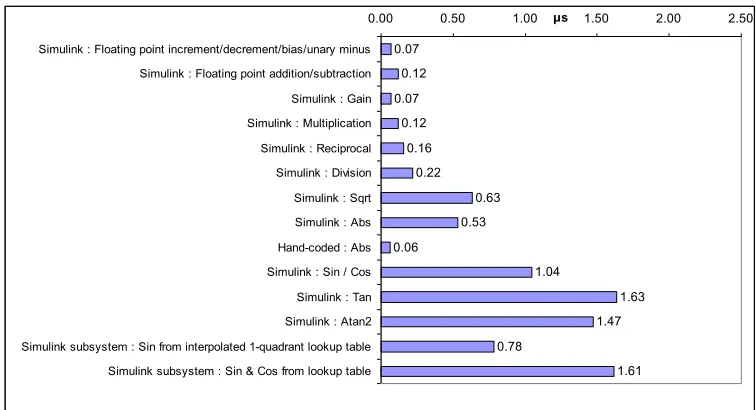
Fig. 2. Benchmarking results (average execution time) for 32-bit floating-point operations on the TC1796. Program in flash memory (caching disabled).
1.60
1.30
0.10
0.24
2.33
0.32
0.55
0.00 0.50 1.00 1.50 2.00 2.50
Simulink : Conversion to Int32 via Ceil/Floor/Round/Fix (no saturation checking)
Simulink : Conversion to Int32 via Ceil/Floor/Round/Fix (with saturation checking)
Hand-coded S function : casting to int32 (Ceil/Floor/Round/Fix) (no saturation check)
Hand-coded S function : casting to int32 (Ceil/Floor/Round/Fix) (with saturation check)
Simulink : MOD (uses Floor)
Hand-coded : MOD (without saturation checks)
Hand-coded : MOD (with saturation checks)
[image:2.595.47.547.291.446.2]μs
Fig. 3. Benchmarking results (average execution time) for 32-bit floating-point to int32 conversion operations on the TC1796. Program in flash memory (caching disabled).
It should be mentioned that throughout this work, the Tasking compiler (used to create executable code from autogenerated C code) was used with its optimisation set to “Debug level 2” which attempts to minimise execution time but without “in-lining” repeated function calls, which would significantly increase the program memory requirement. Also, the benchmarks were all executed from the TC1796 flash memory. For the experiments shown in Figs 2 and 3, this was used un-cached. For the larger function measurements, the caching facility was enabled. This allows the TC1796 to cache sections of the flash memory within internal RAM, giving a 20-50% speed improvement.
The Simulink options “block reduction optimisation” and “inline parameters” were also used at all times, both of which help to minimise execution times.
A. Floating point functions
Fig. 2 shows measured times for 32-bit floating point operations on the TC1796. Of particular interest within
power systems are the functions sqrt, sin, cos and atan2. Unsurprisingly, these functions show relatively long execution times, although it should be noted that only 1.04µs is required for a sin or cos operation. This compares favourably with the time taken to extract a value from an interpolated lookup table (0.78µs). Thus, the trigonometric functions should not be explicitly avoided but should only be evaluated where strictly necessary, employing storage and re-use of pre-calculated results wherever possible.
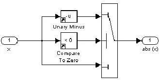
Fig. 4. abs(x) algorithm which executes (on average) 9x faster than the Simulink abs function.
B. Floating-point to integer (int32) conversions
[image:3.595.45.290.491.576.2]Fig. 3 shows measured times for floating-point to integer (int32) conversions on the TC1796. The Simulink functions “Data Type Conversion” combined with the ceil, round, floor or fix operators take 1.3µs or more to evaluate. Interestingly, the versions without saturation checking take longer than those without. This appears to be due to an even slower wraparound function which is used when saturation checking is not enabled. A significant (~5x) speed increase can be obtained by creating single-line “S functions” in Simulink which carry out a native C casting from the floating-point to the int32 datatype, and then combining these with small Simulink functions which provide the ceil, round, floor or fix operations. Fig. 5 shows an example of the round function as optimised. The catch is that native casting is hardware specific and, to date, this is the only known case found by the authors which requires the Simulink code to be modified for different hardware platforms. This can be accommodated by setting a global variable CastingMethod to 1 or 0 for different processors as shown in Fig. 5. CastingMethod is set to 0 for PCs and other processors which natively cast towards zero (fix) whereas the TC1796 natively provides a round operation and CastingMethod must be set to 1.
Fig. 5. Example of the round function provided for different hardware types, using a single-line “S function” to carry out native casting.
Fig. 3 also shows that the mod function as provided by Simulink is extremely costly in terms of CPU time (2.33µs) This is relevant, since such a function is often useful for wrapping or unwrapping of phase within or across the –π<θ<+π boundaries. The reason for the long execution time is that the mod function uses the floor function. Therefore a manual version can be coded to use the native casting as described above. This manual mod
function can be executed in 0.32 to 55µs (dependent on the saturation checks required), a speed increase of 4x to 7x.
III. FULLY “IN-LINING” THE “S FUNCTIONS” Any Simulink “S functions” which are created to optimise speed must “fully in-lined” to obtain the best performance. The Simulink documentation explains this process in some detail. In the case of the native casting from floating-point to integer, the “S function” requires two files to be created. One has a ‘.c’ extension and contains the single-line piece of code:
static void mdlOutputs(SimStruct *S, int_T tid) {
const real_T *dbl = (const real_T*) ssGetInputPortSignal(S,0); int32_T *i32 = (int32_T *) ssGetOutputPortRealSignal(S,0);
*i32 = (int)*dbl; }
The second file has a ‘.tlc’ extension and contains a similar but different line of code:
%function Outputs(block, system) Output %assign pu0 = LibBlockInputSignal(0, "", "", 0) %assign py0 = LibBlockOutputSignal(0, "", "", 0) {
%<py0> = (int)%<pu0>; }
This means that similar but non-identical code sections must be maintained within the ‘.c’ and ‘.tlc’ files. It is possible to partially “in-line” the ‘.tlc’ file by using the code segment:
%function Outputs(block, system) Output
%assign pu0 = LibBlockInputSignalAddr(0, "", "", 0) %assign py0 = LibBlockOutputSignalAddr(0, "", "", 0) {
real_T *dbl = %<pu0>; /* Input signal */ int_T *i32 = %<py0>; /* Output signal */
*i32 = (int)*dbl; }
This allows the same line(s) of core code to be copy-pasted between the ‘.c’ and ‘.tlc’ files. However, this requires additional memory and adds processing time (0.1µs or more, dependent upon the function complexity) to each “S function” call. The same rationale applies to more complex “S functions” such as the delay buffer blocks required for exact-time averaging.
number of signal buffering blocks from 1 to 3 for each average/integral required. The time taken for the original Simulink “Discrete Variable Transport Delay” signal buffer algorithm was measured at 1.50µs on the TC1796 (program flash memory caching disabled) or 0.75µs (caching enabled). A purely Simulink algorithm using the “tapped delay” block was trialled but this resulted in C code which was extremely slow to execute for large buffers. The final optimised “S function” version created by the authors (see [8] for code details) executed in 0.31µs (caching disabled) or 0.23µs (caching enabled). This is more than 3x faster, so 3 of the improved buffers can still be executed faster than 1 of the original Simulink buffers.
V. EXAMPLE OF OPTIMISATION:SINGLE-CYCLE FOURIER ANALYSIS OF 3 SIGNALS AT A COMMON FREQUENCY
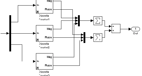
[image:4.595.42.285.311.441.2]The following example shows how the code to carry out Fourier analysis of 3 signals at a common (variable) frequency has been incrementally optimised, using all the techniques previously described.
Fig. 6. Benchmarking of three fixed-frequency Fourier analysis blocks from the SimPowerSystems blockset of Simulink
The starting point is a set of three fixed-frequency “Discrete Fourier” blocks from the Simulink SimPowerSystems blockset (Fig 6). These take 20µs to
execute (see Fig 7). Note that this solution does not account for variable-frequency operation. This is most simply achieved by modifying the “Discrete Fourier” blocks to add variable frequency operation. Most importantly, this means replacing the “Discrete Mean Value” blocks with “Discrete Variable Frequency Mean Value” blocks (all from the SimPowerSystems blockset). The resulting algorithm took 29µs to execute and is the baseline for subsequent optimisation.
The first step is to improve the robustness and accuracy of the exact-time averaging/integrating algorithms. This reduces the time to 26µs, despite that fact that the number of signal buffers is increased from 6 to 18, and that the “S functions” were initially only partially “in-lined”. Fully “in-lining” the “S functions” further reduces the execution time to 24µs. The third step is to split the Fourier algorithms into a “Part A” and “Part B” sections. In “Part A”, all common calculations which are functions of the variable frequency input are calculated. This “Part A” data can be shared with all three “Part B” sub-algorithms, removing substantial repetitions of calculations. This reduces the number is sin/cos operation pairs from 3 to 1, and also optimises the code required to configure the signal buffers and exact-time averaging blocks. Execution time is significantly reduced to 15µs. These steps are described in more detail in [8, 9].
The last two steps to take are identified by the benchmarking exercises. In this case, a single floating-point to integer conversion via the ceil operator is replaced by a manually coded version combined with the one-line “S function” presented earlier. Also, a Simulink mod function is replaced by a manually coded version. These final two steps shave another 1 and 2µs respectively off the execution time.
20
29
26
24
15
14
12
0 5 10 15 20 25 30 35
Three SPS Fixed-Frequency "Discrete Fourier" (6 SPS "Discrete Mean Value" blocks)
First variable-frequency solution (baseline) using 6 SPS "Discrete Variable Frequency Mean Value" blocks
Improved robustness and accuracy using 6 new "exact-time averaging" blocks (# data buffers increases from 6 to 18)
Fully "in-lined" S functions
Share "PART A" data between the three Fourier blocks
Replace a single Simulink double-to-int32 conversion (ceil) with direct casting S function
Replace a single Simulink MOD function with a -pi to +pi check
μs
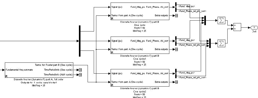
Fig. 8. Benchmarking of three variable-frequency Fourier analysis blocks in the most optimised form.
An overview of the final algorithm is shown in Fig. 8. This executes in 12.3µs, 2.3x faster than the baseline case which takes 28.8µs. The speed increase breakdown is a factor of 1.6x for logical code improvements (the implementation of the “Part A” and “Part B” architecture), and further factor of 1.4x for less obvious improvements such as signal buffering, integer conversions, and the re-coding of abs and mod.
VI. CONCLUSIONS
Although Simulink (combined with its Real-Time Workshop and Embedded Coder extensions) provides a very robust and convenient method of implementing algorithms on multiple platforms, the benchmarking activities and resulting optimisations carried out during this work have proved invaluable in reducing the execution time of several key projects.
This paper has presented results obtained on the Infineon TC1796 microcontroller, on which speed increases of up to 2.3x have been made due to incremental improvements within certain key algorithms. These improvements allow more complex inverter and motor-drive applications to be implemented at higher frame rates.
During the course of this work, the same optimisations have also been applied to other large microgrid management projects on the ADI RTS instrument, with similar proportionate speed improvements.
This work highlights the benefits that some (initially time-consuming) benchmarking activities can have, and particularly the insights it can bring into the performance of both code auto-generation tools and hardware platform capabilities. Although many of the concepts presented in this paper are generic to all hardware platforms, benchmarking on each individual hardware platform would be recommended for any new applications where execution speed is a key factor.
ACKNOWLEDGEMENTS
This work was carried out within the Rolls-Royce University Technology Centre at the University of Strathclyde.
REFERENCES
[1] D. A. Artis, B. K. Heggestad, C. J. Krupiarz, M. A. Mirantes, and J. D. Reid, "MESSENGER: Flight software design for a deep space mission," in 2007 IEEE Aerospace Conference, Big Sky, MT, 2007, pp. 353-361.
[2] N. B. H. Youssef, K. Al-Haddad, and H. Y. Kanaan, "Real-time implementation of a discrete nonlinearity compensating multiloops control technique for a 1.5-kW three-phase/switch/level Vienna converter," IEEE Transactions on Industrial Electronics, vol. 55, pp. 1225-1234, Mar 2008.
[3] D. Hercog, B. Gergic, S. Uran, and K. Jezernik, "A DSP-based remote control laboratory," IEEE Transactions on Industrial Electronics, vol. 54, pp. 3057-3068, Dec 2007.
[4] Infineon Tricore family. Infineon Technologies. [Online]. Available: http://www.infineon.com/cms/en/product
[5] TC1796 Tricore STKTC1796 starter kit. Hitex (UK). [Online]. Available: http://www.hitex.co.uk/shop/index1.html
[6] Real Time Station (RTS). Applied Dynamics International. [Online]. Available: http://www.adi.com/products_sim_tar_rts.htm [7] D. Jovcic, "Phase locked loop system for FACTS," IEEE Transactions on Power Systems, vol. 18, pp. 1116-1124, Aug 2003.
[8] A. J. Roscoe, "Measurement, control and protection of microgrids at low frame rates supporting security of supply," PhD thesis, Department of Electronic and Electrical Engineering, University of Strathclyde, Glasgow, 2009.