Iowa State University Patents
Iowa State University Research Foundation, Inc.
12-6-1977
Recording soil penetrometer
William I. Baldwin
Iowa State UniversityWesley F. Buchele
Iowa State UniversityFollow this and additional works at:
http://lib.dr.iastate.edu/patents
Part of the
Bioresource and Agricultural Engineering Commons
This Report is brought to you for free and open access by the Iowa State University Research Foundation, Inc. at Iowa State University Digital Repository. It has been accepted for inclusion in Iowa State University Patents by an authorized administrator of Iowa State University Digital Repository. For more information, please [email protected].
Recommended Citation
Baldwin, William I. and Buchele, Wesley F., "Recording soil penetrometer" (1977).Iowa State University Patents. 9.
Recording soil penetrometer
Abstract
A recording soil penetrometer comprising a frame hav- [11] [45] 4,061,021 Dec. 6, 1977 ing upper and lower
ends with a penetration probe extending downwardly from the lower end of the frame for penetration of the
ground. A handle is operatively yieldably vertically movably mounted on the upper end of the frame for
forcing the probe downwardly into the ground. A recording drum is rotatably mounted, about a vertical axis,
on the frame and is adapted to have pressure sensitive recording paper mounted thereon. A ground-engaging
apparatus is vertically movably mounted on the lower end of the frame. A rubber foot is provided on the lower
end of the ground-engaging apparatus for engagement with the ground. A scriber is mounted on the upper
end of the ground-engaging apparatus which is adapted to scribe the recording paper on the recording drum.
A force link apparatus operatively interconnects the handle and the recording drum for causing rotation of the
drum relative to the force required to cause the probe to penetrate the soil. The scriber scribes a
depth-penetration resistance graph on the recording paper as the probe penetrates the soil.
Disciplines
Bioresource and Agricultural Engineering
United States Patent
[191Baldwin et al.
(54] RECORDING SOIL PENETROMETER [75] Inventors: William I. Baldwin; Wesley F. Buchele, both of Ames, Iowa [73] Assignee: Iowa State University Research
Foundation, Inc., Ames, Iowa [21] Appl. No.: 763,572
[22] Filed: Jan. 28, 1977
[51] Int. 0.2 ... ~ ... GOlN 3/40 [52] .
u.s. a ...
73/84 [58] Field of Search ... 73/84, 81, 89 (56] References CitedU.S. PATENT DOCUMENTS
2,130,751 9/1938 2,259,491 10/1941 3,552,194 l/1971
Meer ... 73/84
Roller ... 73/89
Hawes ... 73/84
Primary Examiner-Jerry W. Myracle
Attorney, Agent, or Firm-Zar1ey, McKee, Thomte,
Voorhees & Sease
[57] ABSTRACI'
A recording soil penetrometer comprising a frame
hav-[11] [45]
4,061,021
Dec. 6, 1977
ing upper and lower ends with a penetration probe extending downwardly from the lower end of the frame for penetration of the ground. A handle is operatively yieldably vertically movably mounted on the upper end of the frame for forcing the probe downwardly into the ground. A recording drum is rotatably mounted, about a vertical axis, on the frame and is adapted to have pressure sensitive recording paper mounted thereon. A ground-engaging apparatus is vertically movably mounted on the lower end of the frame. A rubber foot is provided on the lower end of the ground-engaging apparatus for engagement with the ground. A scriber is mounted on the upper end of the ground-engaging ap-paratus which is adapted to scribe the recording paper on the recording drum. A force link apparatus opera-tively interconnects the handle and the recording drum for causing rotation of the drum relative to the force required to cause the probe to penetrate the soil. The scriber scribes a depth-penetration resistance graph on the recording paper as the probe penetrates the soil.
-r c.::, -
-I ~ I " '
,,
I I 1
II II II 'I'
~ I I
,,
,,
I II II
I I i
1{! Ill
I
'I
!
I6 Qaims, 4 Drawing Figures
U.S. Patent
Dec. 6, 1977
4,061,021
.Z9
L4
Z4-3.
'I·t.B
tiC.--
¢.8-
3(,.A~
3
3.
g;
511-70
' ---~"'f:,() ----50go
~0 ~0
~-s 58
I
II
go
1
~~
1!, !I ti
l:
III
,, I' I•
I'
II
J:
,,
6(,.
if
IP¢
1
4~061,021
2
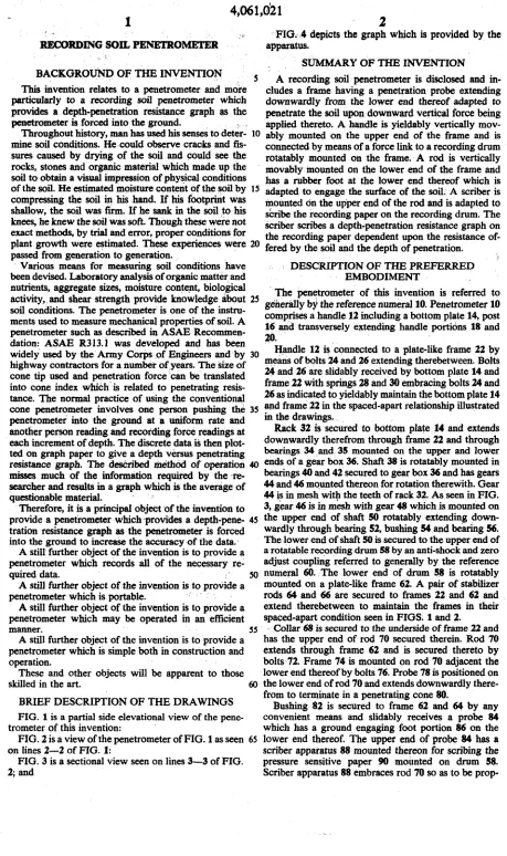
RECORDING SOIL PENETROMETER
FIG., 4 depicts the graph which is provided by the apparatus.
SUMMARY OF THE INVENTION BACKGROuND OF THE INVENTION
. · · · · S A recording soil penetrometer is disclosed and in-This invention relates to a penetrometer and more eludes a frame having a penetration probe extending particularly to a recording soil penetrometer which downwardly from the lower end thereof adapted to provides a depth-penetration resistance graph as the penetrate the soil upon downward vertical force being penetrometer is forced into the ground. ; . applied thereto. A handle is yieldably vertically
mov-Throughout history, man has used his senses to deter- 10 ably mounted on the upper end of the frame and is mine soil conditions. He -could observe cracks and fls- connected by means of a force link to a recording drum sures caused by drying of the soil and could see the rotatably mounted on the frame. A rod is vertically
r~ks, ston~ an~ org~c ma~erial whic~ made up_ the movably mounted on the lower end of the frame and soil to obtain a VJSual unpresston of phys,tcal conditions has a rubber foot at the lower end thereof which is of the so~. He estim~t~d ~oisture con~nt of the_ !!Oil by 15 adapted to engage the surface of the soil. A scriber is compressmg th~ soil m his hand. If ~s footpt;mt w~ mounted on the upper end of the rod and is adapted to shallow' the soil was. ftrm. If he sank m the soil .to his sCribe the recording paper on the recording drum. The knees, he knew the
SC?il
was soft. Though these ."":'ere not Scriber scribes a depth-penetration resistance graph on exact methods, by trial_and error, proper ~ndttions for the recording paper dependent upon the resistance of-plant growth were ~tunated. Th~ expenences were 20 fered by the soil and the depth of penetration. passed from generation to generation. .· Various means for measuring soil conditions have DESCRIPTION OF THE PREFERRED
been devised. Laboratory analysis of organic matter and EMBODIMENT
nutrients, aggregate sizes, moisture conte,tt, biological The penetrometer of this invention is referred to activity, and shear strength provide knowledge about 25 generally by the reference numeral10. Penetrometer 10 soil conditions. The penetrometer is one of the instru- comprises a handle 12 including a bottom plate 14, post ments used to measure mechanical properties of soil. A
penetrometer such as described in ASAE Recominen- 16. and transversely extending handle portions 18 and dation: ASAE R313.1 was developed and has been 20· .
-widely used by the Army
eoq,s
of Engineers and by 30 Handle 12 is connected to a plate-like frame 22 9y highway contractors for a number ofyears. The Size of means of bolts 24 and 26 extending therebetween. Bolts cone tip used and penetration force 'can be translated 24 and 26 are. slidably received by bottom plate 14 and into cone index which- is related to penetrating resis- frame 22 with springs 28 and 30 embracing bolts 24 and tance. The normal practice of using the conventional 26 as indicated to yieldably maintain the bottom plate 14 cone penetrometer involves one person pushing the 35 and frame 22 in the spaced-apart relationship illustratedpenetrometer into the ground at a uniform rate and in the drawings. - . another person reading and recording force readingS at Rack 32 is secured to bottom plate. 14 and extends each increment of depth. The discrete data is then plot- dow~wardly therefrom through frame 22 and through ted on graph paper to give a depth versus penet~ating bearings 34 _and 35 mounted
0'!'
the upper and low~r resistance graph. The deSCribed methOd of operation 40 ends. of a gear box 36. Shaft 38 ts rotatably mounted m misses much of the information required by the ,re~ beanngs 40 and 42 secured to gear b_ox 36 and ~as gears searcher and results in a graph which is the average of 44 ~~ 46 moun!ed thereon for rotatton therewtt~. Gear questionable material. 44 ~~ m mesh wtt~ the teeth of rack 32. As seen m FIG. Therefore, it is a principal object of the invention to 3, gear 46 is in mesh with gear 48 which is ~ountect on provide a penetrometer which ,provides a depth-pene- 45 the upper end of sh~ft 50 rota~bly extendm~ ,down-tration resistance graph as the penetrometer is forced wardly through beanng 52, bushing 54 .and beanng .56. into the ground to increaSe the accuracy of the data. · The lower end of shaft 50 is secured to the upper end ofA still further object of the invention is to provide a a rotatable recording drum 58 by an anti-shock and zero penetrometer which records all of the necessary re- adjust coupling referred to generally by the reference quired data. 50 numeral 60 .. The lower end of drum 5$ is rotatably A still further object of the invention is to provide a mounted on a plate-like frame 62. A pair of stabilizer penetrometer which is portable. · rods 64 and 66 are secured to frames 22 and 62 and A still further object of the invention is to provide a extend therebetween to maintain the frames in their penetrometer which may be operated in an efficient spaced-apart condition seen in FIGS. 1 and 2.
manner.
ss ·
Collar 68 is secured to the underside of frame 22 and A still further object of the invention is to provide a has the upper end of rod 70 secured therein. Rod 70 penetrometer which is simple both in construction and extends through frame 62 and is secured thereto by operation. bolts 72. Frame 74 is mounted on rod 70 adjacent the These and other objects will be apparent to those lower end thereof by bolts 76. Probe 78 is positioned on skilled in the art. 60 the lower end of rod 70 and extends downwardlythere-BRIEF DESCRIPTION OF THE ORA WINGS FIG. 1 is a partial side elevational view of the pene-trometer of this invention:
FIG. 2 is a view of the penetrometer ofFIG.1 as seen 65 on lines 2-2 of FIG. 1:
FIG. 3 is a sectional view seen on lines 3-3 of FIG. 2; and
from to terminate in a penetrating cone 80.
[image:5.557.62.521.39.813.2]prop-
4,061,02.1-erly maintained in position relative to the recording paper and the drum.
In use, the pressure sensitive recording paper 90 is mounted on the recording druin 58 by any convenient means. The relative lengths of probe 78 and 84 are such S
that the scriber apparatus 88 will be positioned closely adjacent the lower end of the recording paper when the foot 86 and cone 80 are resting on the. graund. The operator then applies downward force to the handles 18 and lO to cause the cone 80 to penetrate the soil. The 10
foot 86 does not penetrate the soil and maintains the
scribcir apparatus 88 stationary in height with respect to the soil surface throughout the sampling operation. If the cone 80 penetrates the soil without any rC~~istance
being experienced thereby, a s~raight vertical line IS
would appear on the recording paper and sue~ a straight vertical line would indicate the depth to which the cone penetrated the soil. as well as the fact that no resistance was encountered. However, most soils will provide some resistance to the penetration of the C?One 20 80 and such resistance will be experiehced by the force link operatively coi:inecting the handle to the drum. Downward force on the handle, to counteract the resis-tance experie~ced by th<: cone, will result in the springs l8 and 30 being comprCssed and will result .iri t)le rack 25 32 moving. downwardly with the handle 12 relative to frame ll. Downward movement of rack .32 causes gear 84, shaft 38, gear 42, gear 48 and shaft 50 to be rotated relative to the penetration resistance. Rotation .of shaft 50 causes the drum 58 and the recording paper thereon 30 to be rotated about a vertical axis relative to the scriber apparatus so that an 'irregular line will appear on the recording paper.
After the probe or cone has been removed from the soil, the pressure-sensitive paper 90 is removed from the 35
drum. The angular displacement (penetrating resis-tance), while c;m the drum; becomes theY-aXis (force) and is calibrated in pounds per square inch for a given spring rate and cone. The axial length, while on the drum, becomes the X-axis on the rectangular graph arid 40 is the depth reading. ' '
Ithas been observed, when usirig the penetrometer of this invention, that an average of the soil of a given area could be rapidly determined by recording five readings on a single sheet of paper. An average line is then drawn -45 through the five lines by hand. Since the pressure-sensi-tive paper is not graph paper, a graph template should be placed over the paper arid the average readmgs read from the graph.
This method of sampling and recording soil strength
so
has several advantages over the standard penetrometer which is comprised of a proVing ring and a dial indica-tor in that the device of this invention provides a perma-nent record. Additionally, the penetrometer of this invention may be operated by a single perSon jlld the SS
data is automatically recorded.
It has been found that the recording penetrometer of this inventiqn is especially well suited for determining the effect of wheel traffic in the strength of tilled soil
60
6S
and the effect of tillage on the strength of soil. As in other penetrometers, strerigth of 8oil iSi'i'dated to the force and the size of the penetrating cone. The range of this instrument may be changed QY adding or subtract-ing sprsubtract-ings in the force link or by changing the size of
the cone. · ' ·
Thus,: it can be seen that a n:ovel penetrometer has
been provided which. accomplishes'
at
least all of its stated objectives: · - ··we claim:
1. A penetro!Deter comprising,
' a:
frame means having upper and lower ends,a probe means oil the lower end of said frame means for penetrating the soil,
ground engaging' means vertically movably mounted
0~ the lower end of'said frame means,
· a handle means operatively yieldably vertically mov-ably mounted on the· upper end of said frame means, ·•
· · a
recording drum means rotatably mounted, about a . vertical axis, · oJi • Said frame means and beingadapted to have recording paper thereon,
a SC::nber means' operatively connected to said ground ;engaging means for seribing the recording paper, · and means operatively intercoimecting said handle
means to said drum for ·cauSing rotation of said
. 4rum
relative to the force. required to. 91use said·· probe means to penetrate the soil,
said scriber means scribing a depth-penetration resis-tance graph on the recording paper
as
Said probe is penetrating the soil. · . · · .2. The penetrometer. of claim 1 wherein' 'said means interconnecting said hanciie means to drum comprises a force link means. _, .,. ,. . .· , . . ·
. 3. The pe11;etrometer of cla!Jn 2 wherem said force link means comprises .a spring means extending between said. handle means'. and .said frame mean$, and means oonnecting s&id handle .ineans to said drum for convert-ing vertical movement of said handle means, relative to said frame means, to. co~esponding rotational move-ment of said drum.
4. The penetrometer ofclaim 3 wherein said means comprises .a toothed rack secured to said handle means and extending downwardly therefrom, a horizontally disposed rota.table s~ mo1JAted on said fraQte means, a rust gear on said.shaft for rotation therewith and being in mesh with said toothed rack, a second gear on said shaft for rotation therewith, . said drum having a verti-cally disposed rotatable shaft extending upwardlY from its. center .Iongitudinal.axis, a third gear on said. drum shaft in mesh with said second gear.
5. The penetrometer of claim 1 wherein a foot means is provided on the lower end of said ground engaging means for preventing said ground engaging means from penetrating the soil.
6. The penetrometer of claim 1 wherein said probe has a penetrometer cone on its lower end.
• •
• • •