Abstract: The presence of DFIG (Doubly Fed Induction Generator) affecting the stability of the inter-area interconnected power system due to the lagging response of DFIG under undesirable conditions like faults. This paper addresses a Second-order Sliding Mode controller for DFIG to damp inter-area frequency oscillations of the interconnected power system. The proposed heuristic controller is a sliding mode controller of second-order type and works based on the reactive power capability of DFIG. This novel controller is not affected by system modeling uncertainties and unwanted parameter variations. The proposed controller is designed and implemented on 3-bus interconnected system in MATLAB/Simulink environment and the results obtained compared with the conventional controller under different fault conditions to show the effectiveness. Results demonstrated that the sliding mode controller effectively damping inter-area oscillations compared with a conventional controller.
Index Terms: Doubly Fed Induction Generator (DFIG), Multi-Machine Power system, Sliding Mode Controller (SMC).
I. INTRODUCTION
Due to rapid change in demand, environmental and economic issues, the need to produce non-conventional energy sources have developed more popular and acquire the increasing interest of power generation like solar, wind and biomass [1]. DFIG type non-conventional energy source was one of the recommended sources among all non-conventional energy sources due to the availability of wind [2]. Many authors proposed different methods for modeling and controlling of DFIG for increasing the efficiency and also for stability enhancement. It diminishes the stresses on the wind turbine produced from wind gusts and turbulence.
On the other hand, the rapid use of wind power penetration on highly interconnected synchronous generators, the stability analysis of the interconnected power system is of growing concern. In the stability analysis, the dynamics of wind turbines should be cautiously considered, in the interconnected system low-frequency oscillations are more prominent and these are of local and inter-area mode oscillations. Local mode oscillations are due to load or generations etc., variations in one particular area, whereas inter-area mode the oscillations in one area will affect other areas and these oscillations are traveling through tie line between the two areas [5]. The growth of power electronic technology and their usage in interconnected power systems have influenced the power engineers to use various non-linear controllers in the power system. Various controllers related to the integrated power system have been extensively described in the literature [4].
In order to synchronize the wind power generating system into the existing power grid, various methods developed by
different operators based on the grid characteristics. In [7], DFIG based wind farm is synchronized to the grid with reactive power control and five modes are used for examining the proposed method effectiveness by monitoring the stator and rotor power loss of DFIG. In [4], an algorithm is proposed for the reduction of DFIG torque ripples under unbalanced conditions. The grid voltage variations are taken as unbalanced conditions. In [3], wind farm with SVC controller is synchronized with the grid and feed-forward voltage control method proposed. In this method, the availability of SVC reactive power is coordinately controlled with wind farm to improve the stability. Different models of wind farms proposed for transient stability enhancement of large interconnected power systems from various aspects [3-4].
These methods are given relative importance for stability enhancement of the interconnected power system and at most importance given for different DFIG models. In this paper, a second-order sliding mode controller is proposed for stability enhancement of interconnected systems with inter-area oscillations. The proposed method is designed in MATLAB/Simulink environment and tested on 3 bus two area system.
In this paper dynamic modeling of two area system with and without wind farm is described in section-II, sections III and IV describe proposed method and results respectively. Finally, conclusions included in section-V.
II. INTERAREAOSCILLATIONSINPOWER SYSTEM
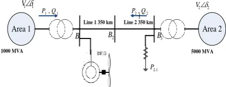
This paper first considers two area two bus system and then wind farm of DFIG type is included, the resultant diagram is taken as 3 bus two area system and it is shown in Fig(1).
Area 1 Area 2
1 1
V V22
1 1,Q
P P2,Q2
1
L
P 1
B B2 B3
Line 1 350 km Line 2 350 km
1000 MVA 5000 MVA
[image:1.595.319.543.579.665.2]Fig. 1 Two machine two-area test system Table.1 Parameters of a Test system Component Parameter details
Tie line 700km length, the operating voltage is 500kv
Hydraulic Power plant
1000MW, 500kv generator connected in area 1 & area 2
Inter area Stability Enhancement of
Interconnected power system using
Second-order Sliding Mode Controller
Load 5000MW resistive load connected in area 2
Transformer s
1000MVA transformer at area 1 and 5000MVA transformer at area 2 are connected
DFIG 150MW
Test system parameters are illustrated in table.1
A. The dynamic model of two area system without wind Power plant
The swing equation describes the behavior of the rotor dynamics. According to the swing equation [1]
) 1 ( 2 2 2 e m P P dt d
H
Where the δ is the angle of the internal e.m.f. of the generator and it gives the amount of power that can be transferred. H represents inertia constant, Pm is mechanical power and Pe
is Electrical power.
The swing equation for two area power system is
2
sin
1
1
1
1
12 2 1 2 1 2 2 2 1 1 1 12
V
V
H
H
P
P
H
P
P
H
ω
mech load mech Load
δ12=Relative rotor angle between two generators
ω12=relative rotor speed between two generators
δ12=δ1-δ2
ω12= ω1- ω2 (3)
B. The dynamic model of two area system with wind Power plant
When the wind power plant is connected at bus 1 the system dynamics can be written as
) 4 ( sin 1 1 1 1 12 2 1 2 1 2 2 2 1 1 1 12
V V H H P P H P P P Hω mech wind Load mech Load
Here Pwind is the active power generated from the wind power
plant From equation 3 the tie-line power between two areas depends upon the relative rotor angle between two areas and the reactive power based upon the voltage magnitude of the buses. The damping can be minimized by injecting reactive power into the system.[7].
)
5
(
cos
12 2 1 2 2 12X
V
V
V
Q
Q
wind
where Q12 is the reactive power transmitted from area 1 to
area 2. Qwind is wind reactive power. in order to keep the
system into synchronism the difference between rotor angles of two areas should be minimum that is nearly equal to zero for the ideal case, it is zero. suppose if any disturbance occurred in the system i.e a double line to ground fault occurrence or due to unbalance between load and generation then the system goes into loss of synchronism that leads to oscillations into the system. for stability concerns, the oscillations should be damped instantaneously. in this paper mainly aims to develop a new robust damping controller i.e. second-order sliding mode controller to damp the system inter-area oscillations by varying the reactive power of wind power plant.
III. SLIDING MODE CONTROLLER
A. Selection of Sliding Variable
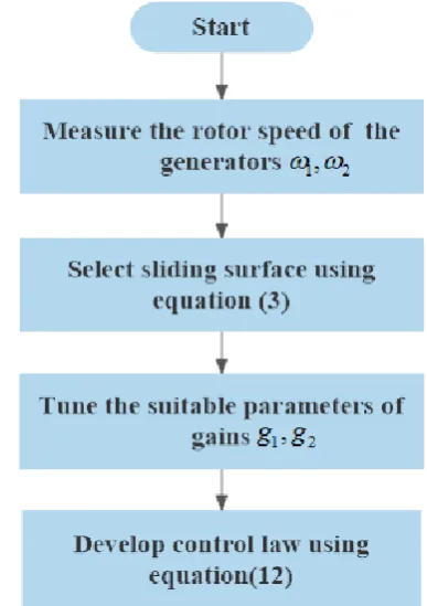
The proposed method aim is to reduce the inter-area oscillations; this is possible by controlling the variables of the controller. The controller first variable is σ and the second variable is the first time derivative of σ . In this paper, the control variable σ is taken as σ = ω12[9],[10] so that the
[image:2.595.329.523.171.446.2]oscillations will reduce. The typical flow diagram of the proposed method is shown in Fig.(2).
Fig. 2 The flowchart of Sliding Mode Controller B. Design of Damping Controller for two area system
By considering the two-area power system shown in Fig.3, choosing the relative rotor angle δ12=0 taken as the reference
angle, the dynamics of the system written ain equation (2) [9],[10].
From the equation (4) we can get the value of V1
)
6
(
cos
12 2 2 2 1
V
X
Q
V
V
windSubstitute the value of V1 in equation (2) we get
)
7
(
cos
sin
cos
sin
1
1
1
1
2 2 2 1 2 2 2 1 1 1 12
wind Load mech Load mechQ
X
V
H
H
P
P
H
P
P
H
ω
From equation (6) gives the relation between the relative rotor angle and reactive power of the wind. But here we cannot change the reactive power of the wind instantaneously. In the conventional control method, there are two loops, the first one is taking care of reactive power and the second one is meant for current control. The
)
8
(
cos
sin
1
1
1
1
2 2 2 1 2 2 2 1 1 1 12
wind wind Load mech Load mechQ
Q
X
V
H
H
P
P
H
P
P
H
ω
)
9
(
1
)
(
)
(
)
(
1
)
(
)
(
)
(
)
(
T
s
T
s
u
s
Q
T
s
u
T
s
s
Q
T
s
Q
T
s
u
s
Q
s
T
Q
u
Q
wind wind wind wind wind w
Where T represents the equivalent inertia time constant of DFIG reactive power control loop
Where u is the additional reactive component; Qwind and
Qwind+ Δ Qref are the reactive powers of wind and net
respectively; Δ Qref is for damping control.
From equation (7) we can get
wind wind windQ
H
H
Q
Q
X
V
d
H
H
ω
cos
sin
1
1
.
sec
1
1
2 1 2 2 2 2 1 12)
10
(
cos
sin
1
1
cos
1
1
1
2 1 12 2 2 2 2 1
T
Q
u
H
H
Q
Q
X
V
H
H
wind wind wind
T
Q
u
Q
d
wind
wind
,
12
, , ,
, (11)cos sin 1 1 cos sin 1 1 cos 1 1 1 2 12 1 2 1 2 1 12 2 2 2 2 1 12 u t F t Q w F u T H H T Q H H w Q Q X V H H ω wind wind wind wind
Where
12 2 0 2 2 2 1 12 1 cos 1 cos sin 1 1 , , , w Q Q Q X V T Q H H t Q w F s w w w w
cos sin 1 1 , 2 1 2 T H H u t F Fig.3 Two Area Power System with SMC
The control variable of the proposed method is expressed as:
2(
12
)
1
g
sign
g
sign
u
With the discontinuous signum function
1, 0
0 , 1 sin
Where the variables g1>0 and g2>0 are the control gains and
12
are the sliding variable and it is expressed as:
(13), , , , 2 1 2 12 1 12 sign g sign g t F t Q w F ω wind
for the wind power plant the reactive power limit is max
min wind wind
wind
Q
Q
Q
The boundary of control law gives
wind wind
wind
wind Q u Q Q
Q min max
The reactive power can be controlled by vdr. The vdr and vqr
can be controlled using PWM technique via dq to abc transformation
IV. SIMULATIONRESULTS
Fig.1 is taken as test system and parameters are shown in table.1. 0.5 p.u. is the maximum DFIG reactive power with a step regulation of ±0.1 p.u.
The simulation results are explained in three cases depends on the type of fault created.
CASE:1
A three-phase fault is created at the transmission line and neat at bus 1 are simulated respectively. The fault occurs at t=1 s and cleared after 1.01 s. rotor angles, rotor speed, tie-line power, voltage and wind
figures 5 to 10. In these figures, blue colour curve indicates wind with conventional represented as without controller and red colour indicates with proposed controller represented as with the controller
[image:4.595.307.548.52.506.2]Fig. 4 Relative rotor angle deviation of generators Fig.4 illustrates the deviation of the rotor angle with respect to time. The conventional controller is taking more than 1 sec for damping this oscillation, whereas the proposed controller is damping this within 0.1 sec with reduced peak overshoot. Fig.5 illustrates the deviation of rotor speed with respect to time. The conventional controller is taking more than 1 sec for damping this oscillation; whereas the proposed controller is damping this within 0.2 sec.
Fig.6 illustrates the deviation of tie-line power with respect to time. The conventional controller is taking more than 1 sec for damping this oscillation; whereas the proposed controller is damping this within 0.2 sec.
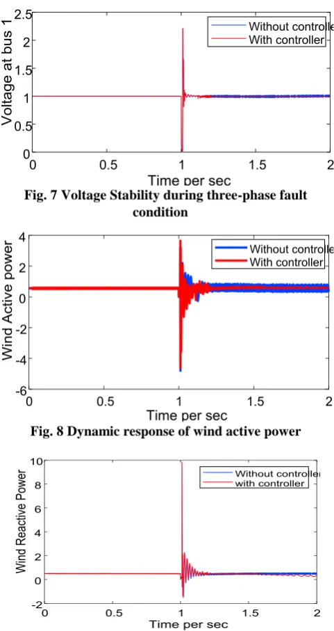
Fig.7 illustrates the deviation of voltage at bus 1 with respect to time. with the conventional controller, the oscillations in voltage are still existing after 1 sec also; whereas the proposed controller is damping this within 0.2 sec.
[image:4.595.51.304.206.782.2]Figs.8 & 9 illustrates the deviation of real and reactive powers with respect to time respectively. With conventional controller, the oscillations in voltage still exist after 1 sec also; whereas the proposed controller is damping this within 0.2 sec.
Fig. 5 Relative rotor speed deviation of generators
Fig. 6 Tie Line Power between two areas
Fig. 7 Voltage Stability during three-phase fault condition
Fig. 8 Dynamic response of wind active power
Fig. 9 Dynamic response of wind active power Case 2:
Increase in load
The power output of a synchronous generator is given as
sin
s f f
X
V
E
From the above equation, it is clear that the increase in load angle δ increases the power output provided field excitation and the generator terminal voltage is kept constant. In the second case, the load is increased to 10% of total load at 1 sec and removed at 1.02 sec. The sliding mode controller regulates the reactive power of DFIG to damp the oscillations immediately. The transient
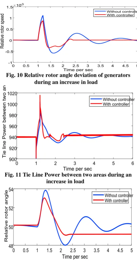
[image:4.595.52.288.494.781.2]Fig.10 illustrates the deviation of the rotor angle with respect to time. The conventional controller is taking more than 5 sec for damping these oscillations; whereas the proposed controller is damping this within 1.5 seconds.
Fig.11 illustrates the deviation of tie-line power with respect to time. The conventional controller is taking more than 6 sec for damping this oscillation; whereas the proposed controller is damping this within 1.5 seconds.
Fig.12 illustrates the deviation of rotor speed with respect to time. The conventional controller is taking more than 5 sec for damping this oscillation; whereas the proposed controller is damping this within 1.5 seconds.
[image:5.595.313.543.63.349.2]Fig.13 illustrates the deviation of voltage at bus 1 with respect to time. With the conventional controller, the oscillations in voltage still exist after 6 sec also; whereas the proposed controller is damping this within 1.5 seconds. Figs.14 & 15 illustrates the deviation of real and reactive powers with respect to time respectively. With conventional controller, the oscillations in voltage still exist after 6 sec also; whereas the proposed controller is damping this within 2 sec.
Fig. 10 Relative rotor angle deviation of generators during an increase in load
Fig. 11 Tie Line Power between two areas during an increase in load
Fig. 12 Relative rotor angle deviation of generators during increase in load
Fig. 13 Voltage Stability during increase in load
[image:5.595.49.289.320.777.2]Fig. 14 Dynamic response of wind active power during increase in load
Fig. 15 Dynamic response of wind reactive power during increase in load
Case 3:
Decrease in load
In the third case load is decreased to 10% of total load at 1 sec and removed at 1.02 sec. The sliding mode controller regulates the reactive power of DFIG to damp the oscillations immediately. The transient responses of the system after the decrease in load are given in Figs. 16 to 21
Fig.16 illustrates the deviation of the rotor angle with respect to time. The conventional controller is taking more than 6 sec for damping these oscillations; whereas the proposed controller is damping this within 1 second.
Fig.17 illustrates the deviation of rotor speed with respect to time. The conventional controller is taking more than 5 sec for damping this oscillation;
[image:5.595.305.549.381.522.2]Fig.18 illustrates the deviation of tie-line power with respect to time. The conventional controller is taking more than 6 sec for damping this oscillation; whereas the proposed controller is damping this within 1.2 seconds.
Fig.19 illustrates the deviation of voltage at bus 1 with respect to time. With conventional controller, the oscillations in voltage still exist after 6 sec also; whereas the proposed controller is damping this within 1.4 seconds.
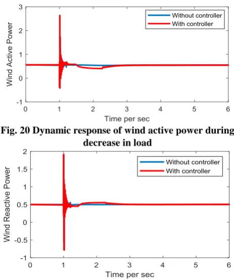
[image:6.595.310.542.53.329.2]Figs.14 & 15 illustrates the deviation of real and reactive powers with respect to time respectively. With conventional controller, the oscillations in voltage still exist after 6 sec also; whereas the proposed controller is damping this within 1.2 seconds.
Fig. 16 Relative rotor angle deviation of generators during decrease in load
Fig. 17 Relative rotor angle deviation of generators during decrease in load
Fig. 18 Tie Line Power between two areas during decrease in load
Fig. 19 Voltage Stability during decrease in load
Fig. 20 Dynamic response of wind active power during decrease in load
Fig. 21 Dynamic response of wind reactive power during decrease in load
V. CONCLUSION
This paper proposed a sliding mode second-order controller for DFIG for damping inter-area oscillations. The effectiveness of the proposed controller is examined in three cases; in all the cases the proposed controller is effective. Proposed method damping oscillations within 2 seconds maximum irrespective of disturbance under any case. The simulation results have demonstrated the performance and robustness of the recommended damping controller REFERENCES
1. P.Kundur, “Power System Stability and Control”, McGraw-Hill, New
York, 1994.
2. Frede Blaabjerg and Ke Ma, “Future on Power Electronics for Wind Turbine Systems”, IEEE Journal of Emerging and Selected Topics in Power Electronics, Vol. 1, no`. 3, pp.139-152 Sep. 2013.
3. L. Dusonchet , F. Massaro,E. and Telaretti “Transient stability simulation of a fixed speed wind turbine by Matlab/Simulink”,
Published in: 2007 International Conference on Clean Electrical Power,2007,pp No.651-655,
4. http://shodhganga.inflibnet.ac.in/bitstream/10603/42630/11/11_chapt er%203.pdf
5. Abhilash Patel, Sandip Ghosh, Komla A. and Folly “Inter-Area Oscillation Damping With Non-Synchronized Wide-Area Power System Stabilizer”, IET Generation, Transmission and Distribution
doi: 10.1049/iet-gtd.2017.0017
6. Omar Mohammed Benaissa, Samir Hadjeri,and Sid Ahmed Zidi “Impact of PSS and SVC on the Power System Transient Stability”, 8th International Conference on Modelling, Identification and Control (ICMIC-2016) Algiers, Algeria- November 15-17, 2016,pp No. 303-307
7. Mahmoud Zadehbagheri , Rahim Ildarabadi , and Majid Baghaei Nejad “Sliding Mode Control of a Doubly- fed Induction Generator(DFIG) for Wind Energy Conversion System” International
Journal of Scientific & Engineering Research, Volume 4, Issue 11, November -2013, ISSN 2229-5518
[image:6.595.54.287.214.482.2]Based Damping Control of DFIG for Interarea Power Oscillations” IEEE Transactions on Sustainable Energy, vol. 8, no. 1, january 2017. 9. Arie Levant,”Sliding order and sliding accuracy in sliding mode
Control”, nternational Journal of Control, 58:6, 1247-1263, DOI: 10.1080/00207179308923053