International Journal of Innovative Technology and Exploring Engineering (IJITEE) ISSN: 2278-3075, Volume-8, Issue-9S, July 2019
Published By: Abstract: In this paper, a microstrip antenna is presented. It has
an H-shaped patch which uses meandered slots an H-shaped DGS beneath the microstrip line to support multiband operation with enhanced bandwidth. The simulated and measured results are plotted to see the performance of the antenna in terms of S11
parameter. The proposed designed resonates at 3.56, 8.04 and 10.57 GHz with a peak gain of 8.39 dB with considerable impedance bandwidth and return loss values at the desired bands. The radiation pattern plots show the conformability with the application it is designed for. The planar structure with a water-resistant substrate makes it suitable for weather radar and other 5G applications.
Keywords: Defected ground structure (DGS), meandering, MSA: microstrip antenna, transverse-electromagnetic mode (TEM).
I. INTRODUCTION
With constant increase in device usage and dependency on the technology, demand for robust and fast communication systems has encouraged development of compact antennas. Performance characteristics of a communication system is strictly dependent on the antenna type as well as on its size and placement in the system. With a paradigm shift in the utilization of devices, miniaturized antenna modelling has evolved as a prime research area. Other than the compact size constraint, designing antenna with wide bandwidth and ability to cover multiple bands has also taken an exponential leap. In order to fit all this in one frame microstrip antennas offer the best performance as it is light weight, easy to mass produce, compact and is conformable. With shift into the microwave and mm-wave range, frequency of operation is increasing thereby reducing the antenna size, hence MSA’s(microstrip antennas) offer best performance.Conventional MSA’s are by default narrowband, have single resonating frequency, low impedance bandwidth, low gain, larger size and polarization issues. Different techniques have been proposed in the literature to resolve these constraints. For instance, using different patch shapes, meandering, slotting, parasitic patches, implementing DGS (Defective ground structures), frequency selective surfaces, electromagnetic band gap, photonic band gap structures, metamaterials, different feeding techniques and so forth.
Revised manuscript submitted on July 02, 2019 Rashbha Sharma, Geetanjali and Rajesh Khanna, Thapar University, Punjab, India
Different shapes of patch have been adopted for improving the characteristics of an MSA. As in [1], changing the patch shape results in quality factor reduction, which leads to improved bandwidth of antenna, whilst maintaining the planar structure and conformability. Juhua Liu, Shaoyong Zheng, Yuanxin Li, and Yunliang Longin [2] proposed a center fed circular patch antenna with vias, leading to improvement in polarization diversity with return loss at -25dB. S.W lee, Y.J Sung in [3] proposed a reconfigurable antenna rhombus shaped patch antenna with Y-shaped feed for polarization diversity. Both the designs in [2] and [3] offered an improved polarization but support only single frequency band of operation. Implementing a different feeding technique also aids to the improvement of performance of a microstrip patch antenna. As proposed in [4] a differential feeding technique is used to enhance the radiation efficiency of a microstrip patch antenna. In this [4] case the air gap between the ground and patch results in size increment. Similarly, a SIW patch antenna [5] results in better return loss parameters and improved impedance bandwidth by compromising the cost effectiveness and simple structure of a microstrip patch antenna.
Multiple band coverage with a considerable bandwidth is introduced in the MSA by introducing slots and meandered slits. A compact wideband dielectric resonator antenna with meandered slot ring and cavity backing is proposed in [6]
enabling animproved radiation efficiency.
Chow-Yen-Desmond Sim, Tuan-Yung Han and Yan-Jie Liao, proposed a Frequency Reconfigurable Half Annular Ring Slot Antenna design in [7] capable of covering multiple frequencies starting from 2GHz until 4.5GHz only. Jiade Yuan, Jiamin Zheng, and Zhizhang (David) in [8] proposed a Compact Meandered Ring Antenna Loaded with Parasitic Patches and a Slotted Ground for Global Navigation Satellite Systems (GNSS), with two orthogonal coupling feed lines fed through coaxial probe covering band 1561-1612 MHz, 1566-1594 MHz. this type of antenna is not suitable for higher frequency operations.Consequently, loading patch antennas with metamaterials improves the gain and bandwidth [9] but overall complexity in increased considerably. Along with meandering and slotting the patch of a MSA, introducing a defect in ground structure (DGS) can bring up a
drastic improvement in the structure. Single or multiple
Rashbha Sharma, Geetanjali, Rajesh Khanna
An H-Shaped Microstrip Antenna with
An H-Shaped Microstrip Antenna with Meandered Slot Lines and a H-Shaped DGS For Multiband Operation.
defects can be considered as DGS [10]. On the choice of type of application relevant type of DGS can be implemented [11]. As suggested in [12], a ground slotted antenna is proposed which is capable of covering X-band with 2.74Ghz of bandwidth and a considerable gain of 7.8dBi. However, the size of the proposed design is relatively large and also antenna is covering only one band.
In this pa*(per a noveldesign of H-shaped patch MSA with coaxial feed is presented in which the patch shape is modified by meandering and slotting. An H-shaped defected ground structure has been introduced beneath the microstrip line contributing to an improved return loss (S11) response. The antenna creates multiple resonances at C band by resonating at 8.05GHz with 847MHz bandwidth and X band by resonating frequency at 10.57GHz with 653 MHz bandwidth, with peak gain of 8.39 dB at 10.57Ghz. Thereby the antenna is capable of covering a wide range of frequencies and qualifying for 5G applications.
II. ANTENNADESIGN
[image:2.612.317.552.196.359.2](a) (b)
Figure 1: Proposed antenna a) Front View b) Back View
The final geometry of the proposed microstrip antenna is shown in fig.1. It comprises of a patch on one side of the substrate and ground on the other. It constitutes a planar structure mounted on a DupontTM Tefzelsubstrate with permittivity 2.3 and loss tangent of 0.019 at 3GHz with dimensions of Lg×Wg×h. An H-shaped patch of copper with thickness t is mounted on the one side of substrate with dimenions Lp×Wp which are calculated using transmission line analysis and equations of rectangular patch antenna [13]. Under this model, the patch antenna is represented in the form of two slots of width W and height h separated by length of L. The electric field is confined majorly to the dielectric substrate whereas some parts of it are in air, as a result fringing takes place. Thus, the transmission line cannot support the
transverse-electromagnetic mode (TEM) mode as phase
Figure 2: Formation of (a) radiating slots, (b) field lines in the microstrip antenna [13].
substrate) and an effective relative permittivity is
calculated as specified in (1). Consequently, in order to account TM10 mode, the effective length of patch is calculated as specified in (3), where ∆L is given in (2) and L is selected to be slightly less than λ/2, where λ is the wavelength in dielectric medium and is equal to λ0/ . TM10 mode implies that the field varies as only one cycle of λ/2 along the length and there is no variation along the width of the patch. Also, the width of the patch is specified according to the frequency of operation given in (5).
Effective length of patch
For a given resonant frequency, effective length is given as
Effective Width of the Patch is given as
The patch comprises of meandered lines of area Lmv×Wmv along the center and vertical slots along the edges with dimensions Lv×Wv. The two U-shaped slots of dimension Lu×Wu are also etched at a distance of 20mm from top and bottom edge. The antenna is excited with a coaxial feed with inner and outer diameter of 0.6 mm and 2.1mm located at (7,16). A PEC (Perfect Electric Conductor) ground with thickness t is formed on the other side of substrate sheet with dimensions Lg×Wg×t. A Defected Ground Structure is introduced by loading an H-shaped slot in the ground plane. Two U-shaped slots of equal dimension Lug×Wug are cut from rectangular slot with dimension Lgp×Wgp to form an H-shaped DGS. The final dimensions of various parameters are listed in TABLE1.1. All the specifications are decided using the transmission line model [14].
Table-1.1
Optimized Geometric Parameters (Unit:mm) Parameters Values (inmm)
Lp 37
Wp 28
Lg 51
Wg 42
h 2.3
Lv 28
Wv 2
Lmv 19
Wmv 1.3
Lu 8
Wu 9
Lug 5
[image:2.612.332.571.548.766.2] [image:2.612.71.276.626.702.2]International Journal of Innovative Technology and Exploring Engineering (IJITEE) ISSN: 2278-3075, Volume-8, Issue-9S, July 2019
Published By: III. PARAMETRIC STUDY
Various parameters of antenna structure are varied and a parametric study is carried out in terms of geometrical and structural variations. The effect of these parametric variations on the performance of the antenna are observed in terms of S11 and impedance bandwidth.
Structural variations include altering the shape of microstrip patch element from a rectangle to H-shape, by etching two U-shaped slots at a distance of 20mm along the length. Similarly, this modified H-shaped antenna is further loaded with slots along the edges and middle of the patch. As a result, a significant improvement in return loss response is observed as specified in fig.5.
A. It is observed that initially designed rectangular antenna as shown in fig.3 do supports multiband operation with resonating frequencies of 2.52GHz (bandwidth and return loss of 82MHz and -20.44dB), 3.15 GHz (bandwidth and return loss of 112MHz and -16.5dB), 4.12 (bandwidth and return loss of 89MHZ and -14.13dB) and 8.36 GHz (bandwidth and return loss of 244MHz and -14.15).
B. Secondly, by transforming this rectangular antenna into H-shaped antenna as shown in fig.4 it is observed the resonating frequencies 3.15, 4.15 and 8.36GHz tend to vanish and antenna resonates at two different set of frequencies that are 2.56GHz (with bandwidth of 211MHz and return loss of -16.66dB) and 6.98GHz (with bandwidth of 180MHz and return loss of -26.04dB).
C. n the final proposed design as shown in fig.5 the resonating frequencies 3.56GHz, 8.04GHz and 10.57GHz are achieved supporting bandwidth of 50MHz,853MHz and 633MHz along with return loss of -28.12dB, -42.88dB and -41.59dB. By etching the slots onto radiating patch of MSA, shield current gets re-distributed as result of which the characteristic parameters of the antenna such as impedance bandwidth, return loss, directivity tends to change.
Geometrical variations: Geometrical variations are carried out to see the effect of variation in dimension of different parameters on the antenna performance. It includes varying the feed point location, length of slots, meandered lines and defective ground structure. A summary of effect of parametric variations on return loss is given as under.
A. Variation in length of vertical slot lines (Lv):Itis observed that as length of the slot lines is increased by the edges from 20mm to 28mm, the entire S11 response tends to shift towards the left side. The best response is chosen according to the peak gain of 8.8dBi and return loss of -45dB as shown in fig.6.
B. Variation in Coaxial Feed location: Referring to fig.7 it is inferred that by shifting the feed point location towards the edges, promotes multiple
resonant frequencies. No major variation is observed by moving the feed point along the y-axis. As for the case of x-axis, by keeping the feed location near to the origin the resonating frequencies around 3.8 and 5.5 GHz tend to vanish. However, asthe point is shifting towards negative of the axis, three different resonating frequencies namely 3.05, 8.10 and 10.04 Ghz with considerable impedance bandwidth tend to arise.
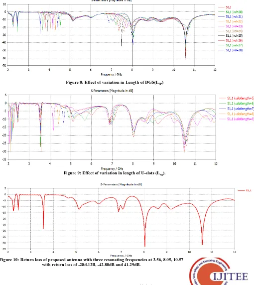
C. Variation in Length of DGS(Lgp): As shown in fig.8, with increase in the length of DGS there is no effect on the resonating frequencies, but the return loss is directly affected. Larger the length of DGS better is the return loss. With S11 of -21dB at length 10mm and -45dB at length 15mm for the resonating frequency 10.05Ghz.
D. Variation in length of U-shaped slots of DGS(Lug): Another important shift in the antenna return loss response is observed by altering the length of DGS u-shaped slots (referring to fig.9). These slots tend to form the H-shaped structure. By increasing the length of DGS slots from 5mm to 10mm a fair shift in the s-parameter characteristics is observed. At 10mm length, only single resonating frequency of 8.05Ghz with a return loss of -38dB is observed, whereas at 5mm three different resonating frequencies with 3.05, 8.02 and 10.52 with return loss of -30dB, -21dB and -26dB is obtained. Therefore, by increasing the length of U-slots to value of 10mm multiband operation is lost
amely 3.05, 8.10 and 10.04 Ghz with considerable impedance bandwidth tend to arise.
E. Variation in Length of DGS(Lgp): As shown in fig.8, with increase in the length of DGS there is no effect on the resonating frequencies, but the return loss is directly affected. Larger the length of DGS better is the return loss. With S11 of -21dB at length 10mm and -45dB at length 15mm for the resonating frequency 10.05Ghz.
F. Variation in length of U-shaped slots of DGS(Lug):
An H-Shaped Microstrip Antenna with Meandered Slot Lines and a H-Shaped DGS For Multiband Operation.
[image:4.612.78.579.328.750.2]Figure 3: Initial Rectangular patch Antenna and its corresponding Return Loss (S11 parameter) response.
Figure 4: Modified antenna with an H-shaped patch and its corresponding Return Loss (S11 parameter)
Figure 5: Final proposed Antenna and its corresponding Return Loss (S11 parameter) response
International Journal of Innovative Technology and Exploring Engineering (IJITEE) ISSN: 2278-3075, Volume-8, Issue-9S, July 2019
1095
Published By:
Blue Eyes Intelligence Engineering & Sciences Publication
Retrieval Number: I11730789S19/19©BEIESP
[image:5.612.76.586.158.730.2]Figure7: Effect of variation in Coaxial Feed location
Figure 8: Effect of variation in Length of DGS(Lgp)
[image:5.612.79.567.162.331.2]Figure 9: Effect of variation in length of U-slots (Lug).
[image:5.612.74.578.525.739.2]An H-Shaped Microstrip Antenna with Meandered Slot Lines and a H-Shaped DGS For Multiband Operation.
III. SIMULATEDRESULTS
The final optimized antenna results obtained after applying parametric variations to the antenna structure are presented below.
A. Return loss (S11 parameter): Return loss (S11 parameter) curve shows that, C and X resonant bands with wide operating bandwidths are obtained.
It is observed that bandwidth of 847MHz at lower frequency band, (4 GHz to 8GHz, with respect to the central frequency of 8.05GHz, and 633MHz, for the upper band (8 to12GHz with central frequency at10.56GHz is achieved. The proposed design is capable of operation at IEEE radar band C at 4 to 8GHz and IEEE radar band X at 8 to 12 GHz. The return loss for the first band so obtained covering frequencies from 7.86 to 8.729 GHz is -42.5dB and as that of second band in the frequency range from 10.246to10.879GHz is -41.5dB which is well below
10 dB level required for the antenna to operate efficiently (fig.10).
B. Gain: The gain of the proposed antenna, at upper and lower bands of operation, has a significant value as shown in fig.11. In lower frequency band (2 to 4 GHz), the measured gain of antenna has a value of 5.45dB, while in the upper band (8 to 12GHz), the gain has a larger value of 7.804 and 8.39dB at 8.06 and 10.57 GHz respectively
[image:6.595.35.561.307.784.2]C. Radiation pattern: The radiation patterns are analysed using CST MWS. The radiation pattern is plotted at the different resonances as depicted in fig.12. Almost Omni-directional radiation patterns at frequency of 2GHz is observed, in azimuthal and elevation plane the pattern resembles the figure of 8. The radiation patter at frequencies 5GHz and 8GHz is somewhat directional. The pattern so obtain is eligible for 5G applications.
Figure 11: Gain of proposed antenna with a peak value of 8.39dB
International Journal of Innovative Technology and Exploring Engineering (IJITEE) ISSN: 2278-3075, Volume-8, Issue-9S, July 2019
Published By: IV. CONCLUSION
A novel design of an microstrip patch antenna with an H-shaped patch loaded with meandered lines and slots along with an H-shaped DGS beneath the microstrip line has been presented. The simulated and measured results are plotted to see the performance of the antenna in terms of S11 parameter. The proposed designed resonates at 3.56, 8.04 and 10.57 GHz with a peak gain of 8.39dB with considerable impedance bandwidth and return loss values at the desired bands. The radiation pattern plots show the conformability with the application it is designed for. The planar structure with a water-resistant substrate is suitable for fixed and mobile satellite communication, as well as for radiolocation. Making it suitable for weather radar systems, regional surveillance systems, satellite position fixing.
REFRENCES
[1] Girish Kumar, K.P. Ray , Broadband Microstrip Antennas. ARTECH HOUSE, INC 2003.
[2] JUHUA LIU, SHAOYONG ZHENG, YUANXIN LI, AND YUNLIANG
LONG,“BROADBAND MONOPOLAR MICROSTRIP PATCH ANTENNA
WITH SHORTING VIAS AND COUPLED RING,"IEEEANTENNASAND WIRELESSPROPAGATIONLETTERS,VOL.13,2014.
[3] S. W. Lee and Y. J. Sung, “Reconfigurable Rhombus-Shaped Patch Antenna With Y-Shaped Feed for Polarization Diversity,” DOI 10.1109/LAWP.2014.2358651, IEEE Antennas and Wireless Propagation Letters.
[4] Neng-Wu Liu, Lei Zhu, Wai-Wa Choi and Jin-Dong Zhang, “A Low Profile Differentially-Fed Microstrip Patch Antenna with Broad Impedance Bandwidth under Triple-Mode Resonance”,DOI 10.1109/LAWP.2018.2850045, IEEE Antennas and Wireless Propagation Letters
[5]Olivier Caytan, Sam Lemey, Sam Agneessens, Dries Vande Ginste, Piet Demeester, Caroline Loss, Rita Salvado and Hendrik Rogier, “Half-Mode Substrate-Integrated-Waveguide Cavity-Backed Slot Antenna on Cork Substrate”, DOI 10.1109/LAWP.2015.2435891, IEEE Antennas and Wireless Propagation Letters.
[6] Symon K. Podilchak, Jonathan C. Johnstone, Mathieu Caillet, Michel Clenet, ´and Yahia M. M. Antar,“A Compact Wideband Dielectric Resonator Antenna with a Meandered Slot Ring and Cavity Backing,” DOI 10.1109/LAWP.2015.2480547, IEEE Antennas and Wireless Propagation Letters.
[7] Chow-Yen-Desmond Sim, Tuan-Yung Han and Yan-Jie Liao , “A Frequency Reconfigurable Half Annular Ring Slot Antenna Design”, DOI 10.1109/TAP.2014.2314314, IEEE Transactions on Antennas and Propagation.
[8] Jiade Yuan, Jiamin Zheng, and Zhizhang (David) A Compact Meandered Ring Antenna Loaded with Parasitic Patches and a Slotted Ground for Global Navigation Satellite Systems (GNSS)”,DOI 10.1109/TAP.2018.2869209, IEEE Transactions on Antennas and Propagation.
[9] Md. Mehedi Hasan, Mohammad Rashed Iqbal Faruque and Mohammad Tariqul Islam, “Dual Band Metamaterial Antenna For LTE/Bluetooth/WiMAX System”, Scientific Reports (2018) 8:1240 | DOI:10.1038/s41598-018-19705-3.
[10] Mukesh Kumar Khandelwal, Binod Kumar Kanaujia and Sachin Kumar, “Defected Ground Structure: Fundamentals, Analysis, and Applications in Modern Wireless Trends”, Hindawi International Journal of Antennas and Propagation Volume 2017, Article ID 2018527.
[11]D. Guha, S. Biswas, and Y. M. M. Antar, Defected Ground Structure for
Microstrip Antennas, in Microstrip and Printed Antennas: New Trends, Techniques and Applications, John Wiley & Sons, London, UK, 2011.
[12] H. Saini, A. Kaur, A. Thakur, R. Kumar, and N. Kumar, "Compact multiband ground slotted patch antenna for X-band applications," 2nd IEEE International Conference on Recent Advances in Engineering & Computational Sciences (RAECS), Chandigarh, 2015, pp. 1-6
[13] James J. R., Hall P. S., and Wood C., “Microstrip Antenna Theory and Design”, London, United Kingdom, Peter Peregrinus, pp. 87-89, 1981-include it in references and Put ref no. for this here
[14] Constantine A. Balanis, “ANTENNA THEORY ANALYSIS AND DESIGN”, John Wiley & Sons,2005.
AUTHOR DETAILS
Rashbha Sharma received a B.tech degree in ECE in 2012 from Amity University,Noida and Mtech degree in ECE in 2016 from JIIT, Noida. She worked as an assistant professor at Lovely Professional University. Phagwara from 2016-17. Presently, she is research scholar at Thapar Institute of Engineering and Techology,Patiala. Her main research interest includes Multibnd antennas, Wireless Communication, MIMO and 5G.
Geetanjali received her Masters in Electronics and Communication Engineering from BBSBEC, Fatehgarh Sahib in 2010 and Ph.D. degree from Thapar Institute of Engineering and Technology in 2018. Presently, she is a lecturer at Thapar Institute of Engineering and Technology, Patiala. Her main research interests are design and optimization of Microstrip antenna, Multiband and wideband antenna, and Wireless communication networks. She has published many papers in journals and conferences on Microstrip antenna and wireless communications networks.
![Figure 2: Formation of (a) radiating slots, (b) field lines in the microstrip antenna [13]](https://thumb-us.123doks.com/thumbv2/123dok_us/8193126.258586/2.612.332.571.548.766/figure-formation-radiating-slots-field-lines-microstrip-antenna.webp)