International Journal of Innovative Technology and Exploring Engineering (IJITEE) ISSN: 2278-3075, Volume-8 Issue-12, October 2019
Abstract: We focused on indoor location tracking of an AGV (automatic guided vehicle) in crematorium. Our concern is that it should transport a dead body safely from the loading place to the designated furnace without stopping in transit. The entire path can be divided into four sub-paths: straight-line, deceleration, rotation, and path reentry. Since these sub-paths have different driving conditions, the method of location tracking to be applied for each sub-path is quite different. In the straight line sub-path, a method of finding the defined path by recognizing landmarks using infrared sensor and image sensor is applied. In the deceleration sub-path, BLE beacons are used to tell the AGV to slow down for rotation. In the 90-degree rotation sub-path, the speed control of the AGV is performed in three sections: deceleration, constant velocity, and acceleration. Finally, in the path reentry sub-path, image marker based relative distance fingerprinting can control the AGV to move into the furnace safely.
Keywords: Indoor Location Tracking; Automatic Guided Vehicle; Landmark Recognition; Internet of Things
I. INTRODUCTION
R
ecently, crematoriums use automatic guided vehicles (AGVs) [1] to transport a dead body from a loading place to the designated furnace or vice versa while autonomously navigating along predetermined routes. We focused on indoor location tracking of an AGV in a crematorium. Previously, the method of embedding guide lines in the AGV's moving path has been widely used. However, a method of using guideline sensors with artificial landmarks [2] that is relatively easy to install has attracted attention. In this paper, we choose a method of using infrared ray (IR) sensors as more economic one as well as ease of installation. The AGV carries the IR projector and the CMOS array image sensors. It projects IR toward artificial landmarks attached to the ceiling. The landmark as shown in Fig.1 is made of materials that reflect IR well. It has a specific shape that represents both the direction and the identifier (ID). Notice that the three white circles at the corners are used for recognizing the angle (i.e., direction). The gray circles in the dotted line represent the ID. Since the ID is associated with the predefined coordinates, recognizing the landmark will know the current location of the AGV. The AGV receives IR and analyzes the received image of the landmark using the image sensors. Then it calculates the position and direction from the landmark just recognized, and continues to navigate in the direction that the landmark guides.Revised Manuscript Received on October 05, 2019.
* Correspondence Author
Youn-Sik Hong*, Department of Computer Science and Eng., Incheon National University, Incheon, Korea. Email: [email protected]
[image:1.595.366.489.139.244.2]Hye-Kyung Jeon, Department of Computer Science and Eng., Incheon National University, Incheon, Korea. Email: [email protected]
Fig. 1.The 3x3 landmark
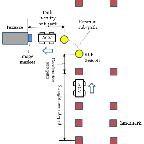
In crematorium, AGV scheduling is not a main issue because multiple AGVs do not move at the same time, unlike industrial sites. Our concern is that it should transport a dead body safely from the loading place to the designated furnace without stopping in transit. The sequence of the forward path consists of the four sub-paths: straight line sub-path, deceleration sub-path, rotation sub-path, and path reentry sub-path as shown in Fig.2. The sequence of the backward path from the furnace to the loading place is the reverse of the sequence of the forward path.
Fig. 2. An AGV’s entire moving path from the loading place to the furnace
Since these sub-paths have different driving conditions, the method of location tracking to be applied for each sub-path is quite different. In the straight line sub-path, the method of landmark recognition using IR is applied. The problem occurred in the straight line sub-path is that sunlight causes scattering effect. Because there are many windows in a crematorium, sunlight affects the accurate recognition of landmarks due to the refraction
and/or reflection of the sunlight.
Youn-Sik Hong and Hye-Kyung Jeon
[image:1.595.309.547.388.626.2]To resolve this problem, the dual landmark recognition algorithm [11] is applied.
If the AGV rotates at the same speed as it does on the straight line sub-path, it is likely to deviate from the predetermined path. Therefore, it is necessary to slow down its speed before entering the rotation sub-path. To solve this problem, two beacons are installed at the location of rotation start and the location of rotation end, respectively. The beacon for broadcasting the information about the point of rotation start to AGVs is installed between landmarks. Notice that an AGV stores the sequence of landmark IDs corresponding to the driving path. Upon recognizing the last ID in the sequence and subsequently receiving the beacon signal, the AGV becomes aware that it is a ready-to-rotate signal for itself.
When the beacon signal is detected by the AGV, it enters the deceleration sub-path. That means it starts to decelerate in preparation for rotation. Our experimental results show that when an actual distance between an AGV with a beacon receiver and a beacon transmitter is 30cm, the accuracy of distance estimation is more than 98%. When it arrives the point of rotation start, the driving control is made so that its speed reaches 30% of the normal driving speed.
In the rotation sub-path and the path reentry sub-path, the driving control using landmarks is not possible because these sub-paths are very short. In the rotation sub-path, the speed control of the AGV is performed in three consecutive sections: deceleration, constant velocity, and acceleration. The purpose of driving control in the rotation sub-path is to enter the AGV within the maximum of 1cm of location error in the predefined path immediately after the end of rotation. It is required to communicate with the beacon installed at the point of rotation end to verify that the AGV has been driven along the prescribed rotation trajectory.
Finally, it is necessary to ensure that it has successfully entered the defined path and at the same time control the speed at which it moves into the furnace. For this purpose, the relative distance is estimated based on the recognized marker size, using an image marker attached to the gate of the furnace. It also checks whether the recognized marker image and the reference image stored in the AGV’s memory are completely overlapped. This ensures that the AGV has entered the correct path. When it enters within the safety distance of the furnace, the gate automatically opens.
This paper proposes a method of controlling the driving path by utilizing different kinds of markers and sensors according to the characteristics of each of the four sub-paths. The rest of this paper is organized as follows: Section 2 summaries related works. We describe the whole process of controlling the moving path in Section 3. Section 4 presents the experimental results used to validate the proposed method. Finally, Section 5 concludes our work.
II. RELATED WORKS
Radio frequency (RF) technologies are used in indoor positioning systems. The RF-based positioning system has a larger coverage area and needs less hardware comparing to other systems [1]. D. Hahnel [3] proposed a probabilistic measurement model to accurately localize RFID tags in the
environment. They used a mobile robot equipped with two RFID antennas to determine the locations of RFID tags. They installed 100 tags in the size with 28mx28m environment. Most of them were installed along the circular corridor of the environment.
Location fingerprinting techniques [4,5] are proposed to improve the accuracy of indoor position measurements by using pre-measured location related characteristics such as RSS (received signal strength). Wi-Fi technology is also used in the position estimation [6]. The pre-measured signal strength values are used to make the fingerprinting maps of the area with respect to different APs (Access Points). Based on the fingerprinting maps of the area, the system [6] uses the k-nearest neighbor’s location algorithm to locate the target node.
Each device’s Wi-Fi chip and antennas have the unique transmission characteristics which are distinct form the other devices [8]. This is called device heterogeneous problem [13]. Recent studies [7,8,9] have focused on how location fingerprinting reduces the error from data stored in the fingerprinting database when receiving Wi-Fi based RF signals from a variety of clients (targeted to mobile users).
To address the above problem, Mikkel [7] proposes hyperbolic location fingerprinting, which records fingerprints as signal strength ratios between pairs of base stations instead of absolute signal strength values. Hao [8] focuses on Wi-Fi based localization system in exhibition venues which have some unique features, for example, many heterogeneous mobile devices with different transmission characteristics. They proposed expectation-maximization algorithm to infer the parameters of the signal-strength-to-distance model so that each mobile device has its own signal strength degradation model. Vahideh [9] proposed deterministic fingerprinting algorithms based on the nearest neighbor algorithm. They compared the positioning performance using Manhattan, Euclidean and Chebyshev distance in terms of the probability of error.
We have proposed the dual landmark recognition algorithm [10] and the relative distance fingerprinting algorithm based on image markers [11] to control the navigation of an AGV in the crematorium. Besides, we also presented a method of driving control of an AGV in the rotation sub-path using BLE beacons [12]. Each of these algorithms has been validated by applying it to individual sub-paths. These techniques were integrated into the system to be proposed, changing its scheme to adapt for each sub-path and improving its function.
III. AN INDOOR LOCATION TRACKING OF AN AGV COOPERATED WITH MARKERS AND
SENSORS
Before implementing our proposed system, the world coordinate system must be configured through map building. The map building is the task of generating the actual location of the landmarks to be placed. This means that the locations of all the landmarks are treated as the single coordinate system. A set of landmarks are deployed at a certain distance in a grid structure in the entire working
International Journal of Innovative Technology and Exploring Engineering (IJITEE) ISSN: 2278-3075, Volume-8 Issue-12, October 2019
200cm. It can be seen that a dead zone or an overlapped zone may occur depending on the straight line distance between the landmarks. This type of interval setting is likely to result in the overlapped zone. The reason for this setting is to recognize at least two landmarks, as discussed in Section 3.1. Notice that the AGV stores the sequence of the landmark IDs it needs to trace in the memory before departure. Each landmark ID is mapped to the actual location of the world coordinate system configured through the map building.
The entire path that the AGV navigates from the loading place to the designated furnace are divided into the four sub-paths as shown in Fig. 2. In this chapter, we propose a method of controlling the driving path by utilizing different kinds of markers and sensors according to the characteristics of each sub-path.
A. Landmark based location tracking
[image:3.595.306.540.51.140.2]A typical landmark is made up of a combination of 3x3 points (marked as circles) in 8 locations, as shown in Fig.3(a). Each of the horizontal and vertical lines in which each point is displayed has a predetermined weight. The weights of the horizontal lines are 0x01 (=1, in decimal), 0x02 (=2), and 0x04 (=4) in hexadecimal. Similarly, the weights of the vertical lines are 0x01 (=1), 0x10 (=16), and 0x100 (=256). Each point representing the ID has a value multiplied by the weight of the horizontal and vertical lines. The ID of the landmark is the sum of each point representing the ID. The landmark ID in Fig.3(b) is 2, and the landmark ID in Fig.3(c) is 50. Notice that the combination of 3x3 landmark can represent the total of 31 IDs.
Fig. 3. (a) the weighted values, (b) the landmark with ID=2, (c) the landmark with ID=50
[image:3.595.309.545.356.446.2]The IR module attached to the AGV identifies a landmark by projecting 10 IRs per second (typical). For example, when the ceiling is 2.4m high, the measureable range to detect a landmark is 2.5m(min.) to 3.0m(max.) in diameter as shown in Fig.4(a). The resolution of the heading angle is one degree. In order to guide the direction of the AGV, the landmark is arranged so as to point to one of the four directions (north, south, east, and west). Therefore, the heading angle can be obtained by calculating the angle difference between the defined moving direction and the recognized marker image as shown in Fig.4(b).
Fig. 4. (a) the scanning range of the IR projector, (b) the calculation of the heading angle
The AGV knows its current location extracted from its local memory by using the recognized landmark ID. Also, it is possible to predict through the heading angle whether it has deviated from the defined path in the straight line sub-path.
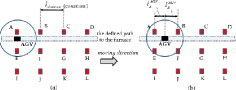
[image:3.595.48.284.431.561.2]A typical method of tracking locations based on IR sensors is to recognize only one landmark at a time. However, because the landmark does not provide checksum for error recovery, we cannot make sure whether the data read from the landmark is reliable or not. To resolve such problem, more than two landmarks will be recognized at the same time [10]. Besides, the previous landmarks which were confirmed as a reliable estimation will be used as the reference for checksum.
Fig. 5. the illustration of the landmark based location tracking Let the sequence of the landmark IDs stored in the AGV be “ABCD”. Assume that it navigates on the defined path to the furnace as shown in Figure 5. At initial, it recognizes two landmarks, A and E, as shown in Fig.5(a). The AGV selects the landmark A included in its sequence as the reference for the next checksum. Next, as shown in Fig.5(b), it recognizes the four landmarks, A, B, E, and F. However, based on the landmark A stored as the checksum, the AGV knows that it travels along the normal route. The landmark B is then chosen as the checksum. In addition, the approximate location of the
AGV is determined by the center (
1
/
2
(
l
AAGV
l
BAGV)
)of the two landmarks, A and B.B. The speed control using BLE beacon to prepare rotation
Two beacon transmitters are buried under the floor at the location of rotation start and the location of rotation end so that the AGV slow down its speed before entering the rotation sub-path. Notice that it is equipped with a beacon receiver. One beacon transmitter to inform the AGV of the point of rotation start is installed between landmarks. The other beacon transmitter to inform the
entrance to a furnace. Upon recognizing the last ID in the sequence (50, in Fig.6) and subsequently receiving the beacon signal, it becomes aware that it is a ready-to-rotate signal for itself. On receipt of the beacon signal, it decelerates its speed
[image:4.595.50.286.140.216.2]in two steps, that is,
v
"
v
'
v
normalas shown in Fig.6.Fig. 6.the two-stage deceleration to prepare rotation using BLE beacons
Experiments were conducted to find the distance at which the beacon signal is reliably received. For the experiments, we selected iBeacon [13], which uses the Bluetooth 4.x based LE (Low Energy) protocol (a.k.a. BLE beacon). Notice that the transmission power was set to an intermediate transmission power (-12 dBm), and the transmission period is set to 100 ms (10 signals per second). The distance between the AGV and the beacon transmitter is set to 5cm, 10cm, 20cm, 30cm, 50cm, 70cm, 100cm, 150cm, and 200cm. The error range of distance estimation is set to ±10% of the actual distance. Experiments were carried out 3,000 times for each distance and the results are summarized in Table 1. For example, when the distance between the beacon transmitter and the AGV was set to 30cm, the error ratio of exceeding the allowable range(27.0cm~33.0cm) was 11.3% (338 times).
Table-I: The error ratio of distance estimation with respect to an actual distance
Distance[cm] No of received beacon
signals exceed the range Error ratio[%]
5 4 0.13
10 147 4.9
20 163 5.4
30 338 11.3
50 70
595 983
19.8 32.7 100
150
1,511 1,704
50.4 56.8
200 1,727 57.6
Experimental results show that the possible range of distance estimation based on beacon signal is within 50cm. Within this distance, a beacon can be used to estimate distance with less than 20% of the error rate. Therefore, the AGV decelerates in two stages from the time of beacon recognition until the point of rotation start is reached. It decelerates to 30% of its normal speed (1km/h or 27.8cm/s) when it is in the range of 50cm to 100cm from the beacon. Subsequently, if the distance from the beacon is less than 50 cm, it decelerates by 20%. When it reaches the point of rotation start, its speed becomes 50% of the normal speed.
C. The precise control of AGV’s velocity during rotation In the rotation sub-path, it is necessary to control the AGV’s speed to rotate along the pre-determined trajectory. In the actual AGV, the motor connected to each wheel is controlled by the PID (proportional–integral–derivative) controller. To move the AGV forward or backward, the
direction of rotation of the left and right motor is reversed. This is because two identical motors face each other. The control process of 90-degree rotation using the PID controller is as follows:
1) In the straight line sub-path, set the PID value as constant (i.e., 1 km/h) for driving at the constant velocity.
2) The rotation sub-path is divided into a set of linearized segments. Then a linear control scheme is applied to each segment. Assuming unit time, the target speed in each segment is the start speed plus a constant value (i.e., slope). For example, when the slope in the segment L1 is a, v2= v1+a. If the slope from the L1 to the L3 is the same, then
v3=v1+2a. In the linear segment, the velocity is a constant and varies by a constant value.
The rotation sub-path is divided into three sections: deceleration, constant velocity, and acceleration and the speed of the inner wheel is changed to control the speed. In the rotation sub-path, the speed is defined by the angular velocity and the angular speed v . Notice that =/tand
v=r, where r is the radius of rotation.
3) Let the
v
0
r
0 be the velocity at the point ofrotation start. The target speed
v
c
r
cis specified on theinner wheel. Decrease the PID value of the inner wheel to slow down the AGV’s speed by v. Interrupts are generated and continuously decelerated until the AGV reaches
n
v
-v
v
c
0
, where n is the number of iterations.4) When the AGV’s speed reaches at
v
c, the second section begins. In this section, the PID value is not changed toallow the AGV to rotate stably. The angular velocity
c isconstant because the PID value remains constant.
5) In the third section, accelerate the speed of the inner wheel to match the speed of the outer wheel.
6) Increase the PID value to accelerate the speed, as is the case with deceleration. Adjust the speed of the inner wheel by generating interrupts at regular intervals until it reaches the speed of the outer wheel.
7) If the speed of both wheels becomes constant, the acceleration is stopped. This is the time when the AGV has just completed a 90-degree rotation.
8) The PID values of both wheels are the same, and it moves straight.
For ease of calculation, let t=0 be the time of rotation start.
In addition,
0 and
c is the angular velocity at the timet=0 and the angular velocity at the time
t
d, respectively, asshown in Fig.7. Then, the angular displacement can be obtained as shown in Eq. (1).
d C 0 2
d d
0
(ω
ω
)t
2
1
αt
2
1
t
ω
Δθ
(1)
[image:4.595.51.289.460.573.2]International Journal of Innovative Technology and Exploring Engineering (IJITEE) ISSN: 2278-3075, Volume-8 Issue-12, October 2019
0 d
C
ω
t
2
ω
(2)
If the AGV starts to rotate at the 0 degree and
15
, then the
cbecomes Eq.(3)0 d
C
ω
6t
ω
[image:5.595.49.284.117.282.2](3)
Fig. 7.The angular velocity with respect to time during the rotation sub-path
Therefore, the angular speed
v
cat the timet
d becomesc c
r
v
. This speed is maintained in the constant velocity section. In the last acceleration section, the angular velocity can be similarly obtained. The deceleration section and theacceleration section were set at
0
to20
and70
to90
, respectively. From our experimental results, the error of location estimation after rotation was found to be the smallest when the constant velocity section was set to the maximum(
60
). Therefore, in the actual implementation, both the range of the deceleration section and of the acceleration section is set to within 15 degrees.D. Location tracking based on relative distance fingerprinting
Let us assume that an AGV at the time
t
1 is located at thedistance
d
1 from an image marker. Notice that the image of the marker uses a simple square like 20cmx20cm. Assume that the length of one side of the marker image recognized byits embedded vision sensor is 1
t
l
at thet
1. At the timet
2(
t
1), it approaches the marker more closely (d
2
d
1),and the length 2
t
l
of the recognized marker image is longerthan 1
t
l
. In other words, as the relative distance from thelocation of the AGV to the marker is shorter, the length of the recognized marker image becomes longer.
If the velocity v of the AGV is constant, the remaining
distance
d
2to the marker att
2 can be obtained by the simpleequation,
d
2
d
1-
v
(
t
2-
t
1)
. Conversely, knowingboth
d
1andd
2by using the 1t
l
and 2t
l
can predict thecurrent velocity
v
(
d
1-
d
2)
(
t
2-
t
1)
. Thus, the speed of the AGV can be gradually decelerated according to the distance to the marker. [image:5.595.303.545.128.284.2]The experimental results show that the above relationship holds as shown in Fig.8. Thus using the length of the recognized marker image as a fingerprint may result in a more reliable estimation of the location. We call this approach relative distance fingerprinting [11]. Fig.8 shows the experimental results when using a square of 20cm x 20cm as the image marker. The larger the image size, the more fingerprinting can be obtained. For example, if the image size is 10cmx10cm, the maximum recognition distance is 1.5m long, but if it is 20cmx20cm, the recognition distance is doubled.
Fig. 8. The length of the recognized marker image with respect to the distance to the marker [11]
The relative distance fingerprinting can be effectively used for AGV driving control in dead zones (for example, path reentry sub-path) where the landmark based location tracking is not available. An image marker has the advantage of being able to predict the remaining distance accurately compared to RSSI-based fingerprinting, although the recognition distance is limited. In addition, it is possible to determine whether the driving direction is shifted left or right by comparing the recognized marker image with the reference image stored in the AGV’s local memory as shown in Fig.9.
Fig. 9.The length of the recognized marker image with respect to the distance to the marker
IV. ANALYSIS OF THE PROPOSED SCHEME The information available through the IR module is the landmark ID, the coordinates (x, y, z) for the current location
(unit is cm) and the heading angle (
180
~
180
). First, we conducted an experiment on the recognition of landmarks. Fig. 15 shows the process of recognizing ID 114 after recognition of landmark ID 528 by an AGV. The changes in ID values are set to be large to see if any significant change in ID would be recognized. The moving direction is set to the East and the heading angle should be recognized as zero degree. Notice that in Fig.10, the y-axis represents elapsed time (unit is ms). It takes about 20 ms to recognize a new landmark from the current [image:5.595.307.552.449.536.2]recognition.
Fig. 10. The process of recognizing ID 114 after the recognition of ID 528
With the landmarks normally placed, we tested how they would affect the determination of the AGV ‘s moving direction when intentionally adding the landmark as shown in Fig.11(a). The AGV is affected by recognition of its heading angle, although it follows the predetermined path. As a result, the heading angle deviates from the path exceeding 0 degree as shown in Fig.11(b). The Euclidian distance between landmarks is set to 200cm, considering the crematorium environment. There was no problem in recognizing the landmarks attached to the ceiling even when the distance from
the AGV to the ceiling is more than
[image:6.595.325.522.124.443.2]4.5m.
Fig. 11. . (a) the intentionally added landmark, (b) the heading angle with execeding 0 degree
BLE beacons were installed under the floor. The AGV has a minimum error rate (1.7%) of distance estimation at the point of 5 cm away from the beacon. When reaching within 5 cm of the beacon, the AGV executed the commands to prepare the rotation, but the rotation started at the point up to 2cm away from the expected point. It was analyzed that the location error occurred due to the time delay until the execution result of the rotation commands are reflected in the PID control. Therefore, when executing the rotation command at the time when the AGV enters within 5 cm, it produced the smallest error (less than 1cm) with the point of rotation start.
As shown in Fig.12, the changes in x and y coordinate were tracked in 1 degree increments in order to check whether the accurate control was made in the rotation sub-path. Notice that only the coordinates of the inner wheel of the AGV were displayed. Fig.12(a) shows the changes in x and y-coordinate, and Fig.12(b) shows the rotation trajectory. In addition, the variation of the rotation angle according to the coordinate change is shown in Fig.12(c). In Fig.12, the y-axis represents
the elapsed time (unit is ms). It can be seen that the actual trajectory is an elliptical trajectory, not a circle one. During the actual implementation, the AGV speed was 27.8cm/s in the straight line sub-path, but it was decelerated by more than 70% (about, 8cm/s) just before entering the rotation sub-path.
Fig. 12. (a) the changes in x and y-coordinates during rotation, (b) the rotation trajectory, (c) the variation of
[image:6.595.46.290.234.506.2] [image:6.595.335.546.490.835.2]International Journal of Innovative Technology and Exploring Engineering (IJITEE) ISSN: 2278-3075, Volume-8 Issue-12, October 2019
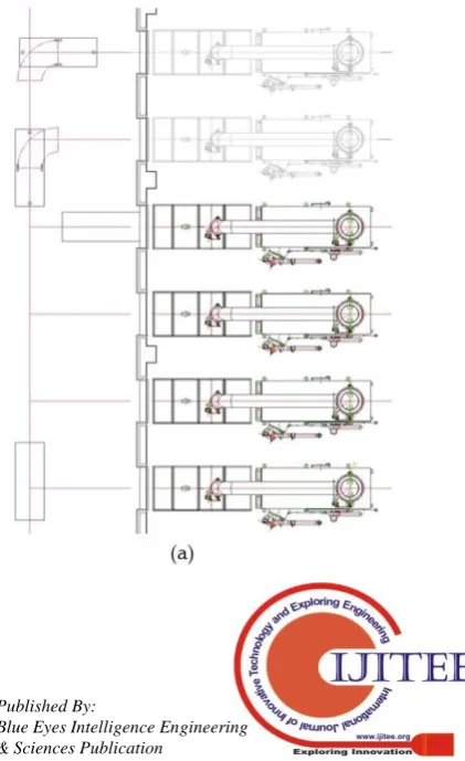
Fig. 13. (a) the actual drawing of the driving path in the crematorium (b) when the AGV arrives at the safe location to enter the furnace, (c) when the AGV enters the
furnace by automatically opening the door Fig.13(a) depicts the actual drawing of the rotation sub-path, the path reentry sub-path and the entry to the furnace. Fig.13(b) and Fig.13(c) show the snapshots of the AGV when it arrives at the safe location after rotation and then it enters the furnace by automatically opening the door of the furnace. Notice that the allowable margin between the entrance of the furnace and the AGV should be kept within 2cm to avoid collision.
V. CONCLUSION
The AGV that carries a dead body in a crematorium should be controlled more precisely than one used in industrial sites. We have divided the entire path into the four sub-paths, and applied the appropriate driving control method for each sub-path independently. The four independent control schemes have already been validated in our previous studies.The individual techniques were integrated into the overall system, changing its scheme to adapt for each sub-path and improving its function. When it finally enters the furnace, the door of the furnace opens automatically only if the location error is within 1cm. As the result of applying the proposed system to the actual field, it was confirmed that the AGV navigates safely without stopping during operation, except when the AGV stops due to an artificially creating an emergency situation. Various types of sensors, such as IR sensors, BLE beacons, and image sensors, were found to operate well according to each driving environment. The proposed system was first installed in the domestic crematorium [16] and is in operation.
ACKNOWLEDGMENT
This work is supported by the 2016 Grant of Incheon National University.
REFERENCES
1. I.F.A. Vis, “Survey of research in the design and control of automated guided vehicle systems”, European Journal Operation Research, Vol.170, pp.:677–709, 2006.
2. Y. Gu, A. Lo, I. Niemegeers, “A survey of indoor positioning systems for wireless personal networks”, IEEE Communications Surveys and Tutorials, Vol.11, No.1, pp.13-32, 2009.
3. D. Hahnel, W. Burgard, D. Fox, K. Fishkin, M. Philipose, “Mapping and Localization with RFID Technology”, IEEE Int. Conf. on Robotics and Automation, pp.1015-1020, ·May, 2004.
4. T. King, S. Kopf, T. Haenselmann, C. Lubberger, W. Effelsberg, “COMPASS: A Probabilistic Indoor Positioning System Based on 802.11 and Digital Compasses”, Proc. ACM Int. Workshop on Wireless Network Testbeds, Experimental evaluation and CHaracterization (WiNTECH), September, 2006.
5. K. Kaemarungsi, P. Krishnamurthy, “Properties of indoor received signal strength for WLAN location fingerprinting”, Proc. Int. Conf. on Mobile and Ubiquitous Systems, pp. 14-23, August 2004.
6. M. Brunato, K. Csaba, “Transparent location fingerprinting for wireless services”, Proc. Med-Hoc-Net, 2002.
7. Mikkel B. K., “Indoor location fingerprinting with heterogeneous clients”, Pervasive and Mobile Computing, Vol.7 pp31-43, 2011. 8. Hao Li, Joseph K. Ng, Victor C. C., William K.C., “Fast indoor
localization for exhibition venues with calibrating heterogeneous mobile devices”, Internet of Things, Vol.3–4, pp.175-186, October 2018. 9. Vahideh M., Andrew G. D., “Determining the best vector distance
measure for use in location fingerprinting”, pervasive and mobile computing, Vol.23, pp.59-79, 2015.
10. H. G. Jeon, Y. S. Hong, “A Moving Control of an Automatic Guided Vehicle Based on the Recognition of Double Landmarks”, Journal of KICS, Vol.37C, No.8, pp721–730, 2012.
11. Y. S. Hong, H. Han, S. Kim, “An Indoor Location-Tracking Using Wireless Sensor Networks Cooperated with Relative Distance Finger Printing”, IEEE Int. Conf. on Ubiquitous Intelligence and Computing, December, 2014.
12. U. J. Jang, Y. S Hong, “A control of moving path on the rotation section for an AGV using BLE beacon in indoor environment”, Int. Journal of Wireless and Mobile Communication for Industrial Systems, Vol.4, No.1, pp. 95-100, 2017.
13. J. Park, D. Curtis, S. Teller, J. Ledlie, “Implications of device diversity for organic localization”, Proc. of IEEE INFOCOM, pp.3182-3190, 2011.
14. Web site, http://www.hagisonic.com 15. Web site, https://estimote.com
16. Web site, Sangbok Memorial Park (domestic crematorium), http://sangbok.cwsisul.or.kr
AUTHORS PROFILE
Youn-Sik Hong He graduated from Hanyang University in electronics engineering, Seoul, Korea, in 1983. He received his Master and Ph. D. degrees in electrical and electronics engineering from Korea Advanced Institute of Science and Technology (KAIST), in 1985 and 1989, respectively. He worked LG Electronics Co. Ltd., from 1989 to 1991 as a senior researcher. At that time, he developed an integrated schematic editor system for efficiently designing VLSI circuits. He also served as a technical consultant for developing embedded software of cellular phone in LG Electronics Co. Ltd from 1998 to 1999. Currently he is a professor at the department of computer science and engineering at Incheon National University.
He received outstanding paper awards from several international conferences, including ICONI 2015 and IICCC 2019. He has published more than 60 technical papers. The title of his latest article is “determination of lying posture through recognition of multitier body parts” published in Wireless Communication and Mobile Computing (2019). He is a member of IEEE, IEICE, KISS, KICS, KAIS and so on. His current research interests include IoT based application using machine learning.
Hye-Kyung Jeon She worked as a programmer at GM Daewoo's computer room for 10 years from 1987. After that, she was in charge of automation project at an information and communication company, and in 2007, she established an engineering company named AndTech Korea Co. Ltd., to manage HMI Department, which integrates software and hardware.
![Fig. 8. The length of the recognized marker image with respect to the distance to the marker [11]](https://thumb-us.123doks.com/thumbv2/123dok_us/8163449.250279/5.595.307.552.449.536/fig-length-recognized-marker-image-respect-distance-marker.webp)