International Journal of Innovative Technology and Exploring Engineering (IJITEE) ISSN: 2278-3075, Volume-8 Issue-11, September 2019
SR-UML: Quality Visualization in Software Design
Vaishali Chourey, Meena Sharma
Abstract: The current requirements of software are intensively based on load sharing, on-demand services, cascading requirements, redundancy for reliability and executing on heterogeneous environments. It needs precise architectural details for development of such software systems. These are large scale software systems with complex interactions amongst the constituent components. Testing for performance and conformance to quality requires perspective modeling fordesigning critical systems. The analysis of these systems is focused on dynamic or execution time behavior for achieving quality. In the same context, this paper redefines Functional Flow Specification for dynamic analysis of critical and collaborating systems. Functional Flow based modeling is a mature concept in the domain of system engineering but is rarely applicable to software systems. Functional Flow Block Reliability Diagram (FFBRD) is a notation for abstract view of the system evolution and interactions. This adopts the specification format of UML and system modeling conventions of SysML specially Enhanced Functional Flow Block Diagram (EFFBD). The flow of data and control are so designed that it best suits the approaches for quality analysis like system reliability. The method proposed is System Reliability with UML or SR-UML for generating test through FFBRD. It also caters to the need of designing software in a familiar formalization for extending, translating and simulating with existing algorithms. From the results collected through various scenarios, we can conclude that SR-UML is instrumental in process improvement of current software development methods.
Keywords : SR-UML, Software Reliability, SysML, Software Testing
I. INTRODUCTION
Software systems are being used in applications ranging from conventional data-intensive business systems to handheld gadget and embedded systems. With the demand of being connected to multiple devices and services, the liabilities of software to be more fast, reliable and maintainable are expected. Various applications on mobile devices, web services or cloud-based enterprise systems have also been a subject of study in terms of architectures for software availability and reliability. The internal structure of the system through reusable components has made applications flexible, modular and robust. Such characteristics ensemble as Software Architectures, enable the components to be shared over a wide spectrum of applications through commercial components (COTS) or reusable patterns. The applicability of a single code to heterogeneous applications through reusability or contracts focuses the need for reliable system design and development.
Revised Manuscript Received on September 05, 2019.
Vaishali Chourey, Department of Information Technology, Medi-Caps University,
Indore (MP), India
Meena Sharma, Department of Computer Engineering, IET(DAVV), Indore (MP), India
The software architecture of complex systems is more of a coalition of systems, executing on demand and exhibit different behavior under different environments [2]. Resultant failures due to erroneous executions, data sharing errors, or even natural causes have raised keen interest in fault-tolerant systems. The need for software testing also evolves with development [1]. The concern for functional correctness has been translated to quality based expectations. The shift to test-driven development has imbibed testing over various stages of life cycle. From requirement validation to design correctness, dependency analysis, fault prediction and such methodologies have led the design artifacts to be tested for correctness before they are implemented as a code. The aspects of quality, productivity, cost of development and performance parameters have also been influenced. Studies reveal that most of the software failures are consequences of design errors neglected in the earlier stages of development. There is a surge to validate designs to prevent fault that propagates in further stages of development. Relevant research in the statistical and mathematical analysis of models for reliability and fault tolerance based on architectural specifications of the systems has been a study of wide interest [4,5,6]. New diagrams and graphical analyses are continuously generated with comfort, constraints and perspective of the system architects. Many diagrams do not scope well over applicability to thelarger domain because of lack of formalization. An attempt to define new conventions in presence of the prevalent notations, the acceptance is meager due to ambiguous interpretations. This is an important aspect of formalizing any new diagram with existing approaches that share a common convention of syntax and semantics. The implicit benefit lies in tools that support the implementation of these model conventions and so easily adapt to the new ones as well. The algorithms facilitate the diagrams to be translated and simulated for analysis. The only challenge lies in the unambiguous execution semantics that still needs to be formally defined. The main objective of this paper is to generate dependable designs based on their quality parameters. Approaches to analyse the software for understanding requirements, handling risks and adopting manageable implementations are already in practice. The basis of making architectural choices based on scenarios of quality attainment is the focus of the work presented here. The strength of this approach is that it works on perspectives to develop in an agile way. Also, the familiarity with UML makes it understandable and easy to adopt for complex communicating code modules. In continuation of our past work [25, 26] that introduced FFBDs in system analysis, we investigated various formal techniques and found FFBRD as defined in this paper with
semantics of UML for
The paper is organized as follows. The first section is the Introduction that covers the background, motivation and contributions of the paper. The second section is the review to the existing body of knowledge in this domain. The third section focuses on the methodology proposed in the paper i.e. SR-UML. It also mentions the model FFBRD to analyse the system and its functionalities. The next section is the result of the study carried out with the new model and methodology. The final section is the conclusion of the research followed by references.
II. RELATED WORK
UML is a versatile tool for planning the software engineering life cycle. The set of diagrams suffices to analysis, specification, design and verification. They are the standards for consistent and comprehensive representation of the system. The modularly structured capability of UML provides flexibility to select those parts of UML that define a domain or context of the application. It is important to explore this flexibility of UML, understand and apply it for developing reliable designs. Most of the review had been related to the diagrams, but in this paper we have included the language constructs of UML for reference. While the focus is on using the models or diagrams in various research, we have used the library of UML to define a new model and therefore, the initial part of the review restricts to the language infrastructure of UML.
A. UML Infrastructure
UML has a self organizing infrastructure that is flexibly extended and reused to any project. The language unit is the concept that renders this flexibility. The language unit is partitioned into diagrammatic aspects. They are context dependent and designed such that only the relevant diagrams are used and even extended to suit the purpose of clearly defining a system. This incremental capability is realized through compliance levels. The compliance at each level pertains to the abstract and concrete syntax for classes, their relationships, notations and interchange specifications. All the evolving diagrams must fundamentally inherit from this characteristic of UML. The modeling architecture of UML [7] is, therefore, a well-adopted industry standard for writing software specifications.
The language architecture and the specifications are important to understand before they are extended for any purpose. The formal specifications are defined as standards for meta-model which can be reasonably and logically mapped in designing software solutions. UML specification is organized as Infrastructure and Superstructure library [8]. The UML architecture along with the design principles of modularity, layering, partitioning, and reuse also defines extensibility. It states that UML can extend with new models in the UML family by extending its InfrastructureLibrary and augmenting it with meta-classes and meta relationships. The infrastructure of the UML defines meta-language core that can be reused to define meta-models namely – UML, MOF (Meta Object Facility) and CWM (Common Warehouse Model). These must be further aligned with XMI to support model interchange. UML Profiles allow customization and creation of new
models with mathematically formal specifications in Object-Z or any such notation.
B. UML4SysML
SysML extends the UML libraries to address system engineering requirements. The design principles may align with the constructs reused by SysML from UML and marked as UML4SysML in the specification of the language. The SysML profiles [9] reuse the semantics of UML profiles. Therefore, the foundation of our work relies on the constructs extended from the profile libraries. The analysis of quality like reliability is well covered with system engineering concepts and the diagrams align with the SysML conventions. The proposed work is a conjunction of the two diagrammatic domains i.e. the notations of quality visualization in the conventions of UML so that diagram is usable and adaptable to industry and academics. We classify our work in the way specified as UML4SysML [10]. The Blocks are more specific than classes. UML also contributes to QoS Profile for specifying the quality of components in the grammar of UML model attributes. The use of Blocks provides a representation to annotate the quality attributes and treat it like any other component in a system for its analysis. The class diagram represented the encapsulated behaviour and the activity represents flow of control. The Block is a meta-structure to include both the characteristics in one model definition. This is a benefit to use the constructs from UMl4SysML.
C. Functional Flow Block Diagram (FFBD)
Functional Flow Block Diagrams are a visual representation of the flow of control and data in system engineering. Since its inception in the 1950s it has become a popular tool for depicting system dynamics and behavior. FFBDs are the formal graphical representations in systems engineering for behavior of complex hierarchical systems. A formal definition is referenced for FFBDs with Communicating Sequential Processes (CSP) in process algebra [11]. It depicted the mathematical perspective of defining the system with concurrent processes. Its graphical equivalent represented functional blocks and the flow of control between interacting blocks. It shows the sequence and the choice structure for the paths of execution of functions. The constructs include AND and OR structures for selecting the path of execution in case multiple flows exist. The blocks can be hierarchically organized and nested to refine the ordering and levels of abstractions for the logical structuring of the components.
International Journal of Innovative Technology and Exploring Engineering (IJITEE) ISSN: 2278-3075, Volume-8 Issue-11, September 2019
FFBDs assume hardware and software components as blocks and are prevalent with analysis and design of embedded systems. FFBDs have been defined with different conventions and analysis. Tools support available for FFBDs is used for developing design specifications. Being a part of the design, the FFBD must comply with the syntax and semantics of other diagrams in design. It is also required that the set of diagrams including FFBD when executed must align with same specifications and simulation. This is indeed an open-ended research to develop FFBD in context to software systems and generate specifications in conformance to standards applied for other diagrams. D. MBT Approaches
Model Based Testing has been an important part of software testing research. The tests have been generated with UML models or transforming the model to an intermediate notation.
Using Activity Diagram:
Activity diagram depicts the flow of control and data during execution of functionality. They are also useful to extract test scenarios through the traversal of the paths in the diagram. A lot of research based on activity diagram and synthesis of test scenarios from them are noted. Linzhang[12]proposed an approach to derive test cases from activity diagram by traversing all the identified paths. The basic path coverage criteria handle the loops and forks as independent path each time they traverse. Bai[13] proposed flattening of the activity diagrams by resolving the paths as
threads as pre-processing before tests are generated. All the disjoint conditions like branch and concurrency are treated as separate trees. Li and Lam proposed the traversal to be a composite activity and not pre-processing it. Chandler [14] suggested the generation of usage scenario from the activity diagram. They employed the XML file to extract the model attributes and define usage scenarios from each iteration. Hartmann [15] annotated the activity diagrams for system level test generation. They also generated test data through category partitioning method for their test cases. Vieira[16] proposed GUI testing with annotated activity diagram and associated classes.
Using Sequence Diagram:
[image:3.595.66.533.424.657.2]Test case identification is also seen in many works that used sequence diagram as input. Binder [17] proposed a set of test requirements from the basic sequence diagram. Basanieri and Bertolino [18] suggested the use case diagram and sequence diagram to be used for test case generation. The ordered sequence of messages corresponds to the test cases generated. Test suites are defined with the use cases and test specifications were derived from the class diagrams associated with each of them. Fraikin and Leonhardt [19] proposed the generation of tests for Java programs. A test stub was proposed for the classes to generate test artifacts. Briand and Labiche [20] used the use cases to derive activity diagram for each sequential constraints. The activity diagrams are transformed into directed graphs for analysis of paths.
Table 1: Techniques for Reliability Assessment Model [4] Category of
Model
Approach / Assumptions
Type of Model Methodology Reliability Model
State-Based Control Flow
Graph for
representing the architecture of system
Discrete time
Markov Chain,
Continuous Time
Markov Chain,
Semi-Markov Process
Architecture Based; Transfer of control
between modules
modelled as Markov property
Littlewood Model,
Cheung Model, Laprie Model, Kubat Model, Gokhale et al. Model, Ledoux Model, Gokhale et al. Reliability Simulation Approach Path Based Combined
architecture and failure behaviour as path based
Failure Model Architecture Based;
System Reliability is computed as probability of failure in different execution paths
Shooman Model,
Krishnamurthy and
Mathur Model, Yacoub et al. Model,
Additive Component
Failure data used to predict overall system reliability
Non-Homogenous Poisson Process
Execution Based;
System intensity failure is expressed as sum of
component failure
intensities
Xie and Wohlin Model, Everett Model,
Cheng [21] proposed a generic model for distributed system’s testing.
E. Reliability Assessment Model
Reliability assessment models have been proposed to analyze and quantify reliability which is an important aspect of software quality. An array of methods exists that are applicable during different phases of software development life cycle. These black box techniques depend on failure data for analyses. The types of software developed
nowadays need analysis based on modules, their interactions and dynamically making choice of substituting modules for quality improvement. The key identifiers in the process of reliability modeling are:
b) Analyzing reliability with choice of the module to increase overall reliability
c) Analyzing interfaces and interactions across the modules
d) Prioritizing critical modules
e) Exploiting design decisions based on results of the analysis
There are three basic categories of architecture based reliability modeling namely – state-based, path based and additive methods. State-based methods use control flow graphs as a representation of architecture following discrete-time Markov chain, continuous discrete-time Markov chain or Semi Markov process [22]. The summary of the techniques, their methodology and shortcomings are given as in Table 1. All the techniques for estimating reliability with models align to one of the techniques for analysis. UML models have been an important study for testing functionality through behavioural diagrams like activity diagram, state charts and sequence diagrams. Converting into graphs, scenarios or interpretations from models have aided test generation from models. The effectiveness is to map it to test for quality attributes in the same manner as functionality is the application of the concept. The simulation of flows in the system makes it amenable to be analysed for its execution time behaviour. This facilitates understanding the performance of the system during the design stage. Such estimations also support optimization for enhanced delivery of the functionality. For the scope of our paper, we have taken reliability as the concern. The tool support of ReliaSoftBlockSim enables the analysis of components of the system for reliability. The conversion of behavioural models into blocks and then modelling their transitions for serial or parallel communications derives the system reliability.
III. PROPOSED METHODOLOGY
[image:4.595.53.286.577.722.2]The existing structure of Blocks define a structural element of the system that encapsulates its attributes and behavior. The models in UML accomplish the representation in control flow and structural composition in a behavior. The idea to collaborate the notations benefits in modeling complex systems with a perspective of quality.
Figure 1: Process Model SR-UML
The proposed methodology [figure 1] takes the requirements specified in the use case or in the documentations available to define a hierarchical structure of the system. This defines the levels of abstraction to view the system in order of their functional dependencies. A functionality evolves to its child
for its realization. This hierarchical structure helps in the managed decomposition of behavior. The second level generates the activity and class diagrams as its analysis phase. The composite of the two evolves into FFBRD to define the structure with more systematic Block wise arrangement. The levels of ordering is retained to keep the integrity in the design.
The FFBRD has a close resemblance to the RBD which is the most suitable model for analysis of system for quality attributes. The tool support for executing and simulating the RBD for reliability, availability and maintainability assessment is enhanced and widely available. This allows statistical analysis and testing of system for reliability in a managed environment. The designs are annotated with the reliability and other attributes derived from the simulations. This adds intelligence to the design and allows the designers to stake any component for optimizing the quality. This flexibility is the benefit of using SR-UML as the process to develop, revise designs and generate tests for the system. To elaborate on model elements of SR-UML the following section focuses on their syntax and use.
Feature Model
[image:4.595.382.467.630.724.2]For understanding the system, its components and its interactions, a hierarchical arrangement of functionalities is proposed. The concept of feature diagram is a tree or graph [23] structure representation of requirements and configurations often termed as features in software product lines. Using this notation enables us to reorganize functionalities (use cases), their derivatives and the non-functional requirements in one place. This extends the use case to another level representation including all the quality parameters left unattended while the requirements were finalized. Feature models are structural and logical ways to model system components and their dependencies [24]. This overcomes the limitation of use case diagram of being brief and adds valuable information regarding the consolidated configuration view of system behavior. This automatically enables partitioning the functionalities for implementation wise grouping and drawing our next diagram in sequence which is FFBD. Therefore, the use of feature in system structural representation is an important part of our paper. The feature model is grammatically expressed as graphs in its abstract syntax with nodes specifying features or functionalities. The features are either compound or primitive. The compound features are iteratively decomposed unless the primitive feature is explored which cannot be decomposed further.
International Journal of Innovative Technology and Exploring Engineering (IJITEE) ISSN: 2278-3075, Volume-8 Issue-11, September 2019
A feature model [figure 2 and 3] is a set of nodes out of which one of the nodes is root and rest are the nodes in lower hierarchy. The root represents the system as a whole. To define it in the syntax of UML, we have assumed each feature as a block with properties as denoted with stereotype as:
<<block>> {encapsulated} FeatureNoteRoot Constraints = NULL
Operations = {op1, op2, op3, .., opn} //the definition of
operations
Parts = all Blocks at level just below the current level References = block description document
Values = NULL
[image:5.595.352.500.125.357.2]Properties = Attributes from Requirements and extendedRequirements pertaining to this block
Figure 3: Feature Model and its Nomenclature The nomenclature of the feature blocks are based on the level to which they belong. The notation follows node_ID.level.sublevel continuing till the leaf node is attained. This allows operations to be aligned to implementation easy data structure.
Blocks
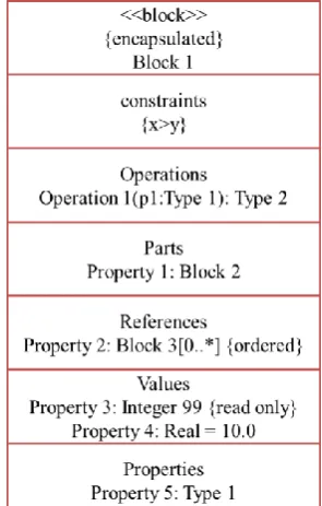
For brevity, we use the definition of Blocks to compose the structure, behavior, properties and operations of the simplest unit of the system. The components in the feature model derived from the logical or physical decomposition of the functionalities have a formal specification in close resemblance to Block Definition Diagram of SysML. The Blocks in our context also defines the priority and the quality metrics of the functionality for reusability with decision based on the metrics. The diagrammatic representation and definition of Blocks is constituted as Block Definition Diagram in line with the UML Class Diagram Blocks are modular units of system description. They are a collection of structural and behavioural features to functionally define a system. Internal block diagram captures internal structure of block to specify its properties in terms of values, parts and reference to other Blocks. We define the Block with the meta-language core and architecturally align it with UML, MOF and CWM. The infrastructure of the new meta-model depends on these and can be defined formally as Block with definition as in figure 4. UML is a well-adapted for design and analysis of various aspects of system and its visualization. The structural and dynamic representations through diagrams like class, activity, and state-charts are foundations to abstract and
[image:5.595.58.277.281.378.2]executable specifications. An inclusion in the dynamic behavior to represent layers of abstractions in one glance and further refining each layer subsequently will strengthen the definition of FFBD in the UML. We have the background of Blocks being defined in SysML that has a close resemblance to the objective of this work.
Figure 4: Block Specification Structure
The generic definitions and syntax of SysML will enable the construction of metamodel for FFBD. The application of FFBD to visualize quality (reliability) in design extends the notation to a new vocabulary of FFBRD. This is a conjugate of flow (dynamics) of UML specifications and analysis of reliability in terms of RBDs. The UML based semantics built upon existing research in software reliability through design is validated with reliability assessment strategies. The target software model that was a functional specification extends to quality specific attributes and generates test artifacts for regression testing. FFBDs in this semantic makes it adaptable to tools and analysis applicable to UML designs. This prevents unambiguous interpretations and fits FFBDs for software design and test modeling. The details of FFBD in the syntax of UML (adapted from SysML) are described further in this section.
Formalizing the FFBRD
FFBRD includes blocks that are functional entities of the system. They are connected to blocks in the manner of being invoked during execution. The flow is conventionally ordered from left to right.The FFBRD takes the requirements from the use case specification. The requirements are briefly analyzed for implementing the functionality and a sequence is drawn as the first level FFBRD.
For the better understanding of system dynamics, we propose a perspective of reliable transactions in the system. And with the attributed blocks, we define the FFBRD in the semantics of UML.
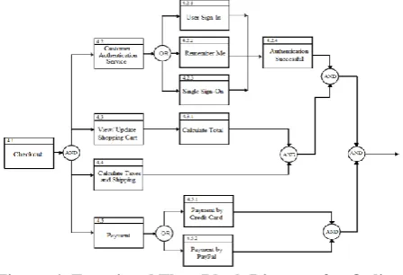
Figure 5: FFBRD Generation through Requirements The functionality which is View Items has alternate ways to be realized i.e. via General Browsing or Customer Authenticated way. The function of the View items utility is to finalize a product for order. The functionality depends on recommendation, wish list, personal information and cart makes it appropriate to realize security and reliability in the design. Similarly, the checkout option accesses the payment information of the customer. Any error in the functionality may lead to fault in the system that affects critical classes. A context can be developed for reliable browsing of the customer. The Reliability View is hence defined to check for the exceptions in the execution of the functionality and handle the errors or faults.
Figure 6: Functional Flow Block Diagram for Online Shopping
The previous works on synthesis of FFBD [25,26] is inspired from use case diagram, component diagram or sequence diagram. The activity diagram is another approach to defining flow in the system. The diagrams are drawn separately to exhibit flow and functionality. The composite diagram is a visualization of both the aspects taken together. The FFBRD contains blocks with properties and communications amongst the blocks to define the structure of the system. The aim of the study is to identify it as the best design alternative to fulfil the quality requirements of the system.
It is done by extending the DI package and define language-specific diagram interchange meta-model. FFBRD is a constrained use of activity diagram with Blocks as structure. It has the following definition
a) Stereotype: <<ffbrd>>
b) Base Class: UML4SysML::Activity {or subtype of <<nonStreaming>>}
SysML::Blocks c) Properties: N/A
d) Constraints: applicable in parameters, actions, activity, execution.
e) Activities defined as streaming in case they provide any output during execution or non-Streaming otherwise
For the clarity in the concept we have taken example of an online shopping system. Its functional requirements are well stated in the use cases.
Specification for Reliability:
QoS Characteristics is a part of <<view>> with a viewpoint for reliability and is written as {viewpoint = reliability
Viewpoint} and in XML as:
<<QoSCharacteristic>> Reliability <<QoSDimension>>
expected-number-service-failures: {direction(decreasing)} <<QoSDimension>>
Operation-semantic: String;
FFBRD are also based on UML classes and extended by UML composite structure. They are the FFBDs extended to include non-functional characteristics along with functional behaviour.
Attributes of the Reliability Viewpoint is given as: stakeholders = “customer”
concerns = “Will the system be reliable?”
purpose = Test the critical functionality rigorously (set test priority to such functionalities)
methods = check operation profile of behaviour and
estimate reliability; maximize reliability through
constraints, fault tolerance and exception handling; include functional viewpoint
languages = “UML”; “SysML”
Associations of the block will include SearchItem,
BrowseItem, View RecommendedItem, ShoppingCart, WishList and dependency on CustomerAuthentication Constraints the flow of data from view, browse should be added to recommendation and conversely the products from recommendation should be displayed on the customer dashboard. The access to the recommendation and wishlist from external classes must be restricted as this shall breach reliability in the behaviour. The operational behavior and the failure model together gives the directions to identify failure, retry functional execution, recover and restart thereby making the functionality FailSafe.
[image:6.595.58.282.415.568.2]International Journal of Innovative Technology and Exploring Engineering (IJITEE) ISSN: 2278-3075, Volume-8 Issue-11, September 2019
But confining it further to reliability, the method used for verification of requirements can be assumed as analysis and test. The analysis enables us to collect data based on simulations of the system and evaluate the attributes by varying the parameters. The data for reliability is collected and is valid only after it is executed. This way, test yields the outcomes and provides input to factual statistics about the component. This data collected over simulations gives us an insight to how the system will behave in the execution time while the data after execution revises the approximate values to actual ones. These are treated as inputs for the testing of a component for reliability. The frequency of the change is noted to give an idea whether the component or stable or affected with interactions from other components. The test profile {UML Test Profile} allows accommodation of these into generation of test cases as:
<<Stereotype>>TestCase :: Operation :: Behavior
The operation and behaviour are meta classes in UML. Activities, state machines and interactions are kinds of behaviour and extended in FFBRD. This facilitates generation of test cases through FFBRD. Similarly, TestComponent is applied to classes and its subclasses as components and nodes. This facilitates inclusion of FFBRD as component in test profiles in the grammar of UML. Context TestComponent
Self.base_Class.oclIsKindOf(Class) Self.base_Class.oclIsKindOf(Component) Self.base_Class.oclIsKindOf(Node)
IV. RESULTS
The notation FFBRD is effective in designing systems for non-functional and quality requirements. The conventions that are close to UML allows the FFBRD to be applicable to practical projects in industry. The most pressing issue of being accepted and being usable is visible with FFBRD. It is
[image:7.595.299.553.137.207.2]also extracted in XML for sharing across platforms. In order to understand the usage pattern of the components data from RETRO project is referenced. A sample is studied for non-functional requirements on a system. The data defines dependency on the model elements to fulfil the requirements.
Table 2: Quality Requirement and its Description Quality Characteristics Quality_ID Quality Description Usability U01 User Friendliness, intuitive
interface
U02 Ease to view requirements Reliability R01 Correctly label elements
R02 Spell correctly R03 System must not crash
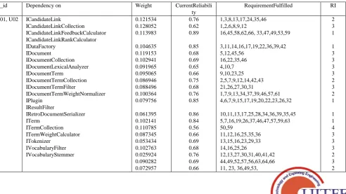
The example project was examined for analysing the two quality requirements- usability and reliability. The requirements were stated as textual descriptions for designing the system. Corresponding to each of the interfaces implemented for handling the system, the requirements were created. Each requirement is numbered from 1 to 66. The table has a column named RequirementFulfilled that corresponds to the requirement number for each requirements of the system. For instance, ICandidateLink corresponds to requirement number 1,3,8,13,17,24,35,46. The current weight is 0.121 based on its usage profile estimated during simulated executions. The current reliability is also calculated for the component ICandidateLink as 0.959228 for t=100s and 50 iterations.It also calculates Probability of Failure, Reliable Life, Mean Life and Failure Rate. This evaluates an attribute named ReliabilityImportance (RI) to be designated to the interface. This value is annotated in the properties of the model. This acts as input to the priority in regression testing when changes occur.
Table 3: Results for Retro Project Implementation
Q_id Dependency on Weight CurrentReliabili
ty
RequirementFulfilled RI
U01, U02 ICandidateLink ICandidateLinkCollection ICandidateLinkFeedbackCalculator ICandidateLinkRankCalculator IDataFactory IDocument IDocumentCollection IDocumentLexicalAnalyzer IDocumentTerm IDocumentTermCollection IDocumentTermFilter IDocumentTermWeightNormalizer IPlugin IResultFilter IRetroDocumentSerializer ITerm ITermCollection ITermWeightCalculator ITokenizer IVocabularyFilter IVocabularyStemmer 0.121534 0.128052 0.113983 0.104635 0.119153 0.102941 0.091965 0.095065 0.086946 0.088496 0.100364 0.079756 0.061395 0.102141 0.110785 0.087345 0.053434 0.102763 0.025924 0.090282 0.072957 0.76 0.62 0.89 0.85 0.68 0.69 0.65 0.66 0.75 0.68 0.76 0.85 0.86 0.84 0.56 0.66 0.69 0.68 0.76 0.69 0.66 1,3,8,13,17,24,35,46 1,2,6,8,9,12 16,45,58,62,66, 33,47,49,53,59 3,11,14,16,17,19,22,36,39,42 5,12,45,56 16,22,35,46 4,10,7 9,10,23,25 2,5,7,9,12,14,42,43 21,26,27,30,31 1,7,9,13,34,37,39,46,57,61 4,6,7,9,15,17,19,20,22,23,26,32 10,11,13,17,25,28,34,36,39,35,45 5,7,16,19,26,37,46,47,57,59,63 50,59 11,12,16,25,35,36 13,15,16,23,29,33 14,16,25,26 12,13,27,30,31,40,41,42 44,49,52,57,56,63,64,66 11, 23, 36,49,53,
[image:7.595.57.550.512.789.2]Reliability Allocation in FFBRD is done through the average reliability achieved through simulating the execution in BlockSim tool. The weightage depict the usage and the reliability importance is derived from the association of the interface with fulfilment of requirements through the specific interface. For the same example there were 66 requirements explicitly defined in RETRO project. An instance of the interface may suffice a few requirements directly or indirectly. We have assumed certain requirements specific to each interface as requirement numbers.
V. DISCUSSION
An important question that arises is why we need a new model or structure when UML is equipped with so many models? The answer is that the sufficiency of models as a standalone convention for testing is not available. Activity diagram independently depicts the flow for a transaction in UML notation. The drawback is that the layer of abstraction for all tasks taken together is not available with the activity diagram. Also, the diagram includes events and activities which does not map to the structural entity which is class. Even if the argument is to see only the behavior in the activity, the hierarchy of the complex but decomposed architecture is not represented. Similarly, the dependency amongst the components exists in the component diagram of UML but the flow is not important in that specification. To bring it into execution, we have to pick the constructs of UML from its meta-model definition as UML infrastructure which is discussed in next sub-section.
Second question is applicability of the new model in any real or practical context. It is possible to handle complex interactions and large scale systems with partitioned abstractions to express it in our notation. For instance, the model can be applied in the Cloud architecture and the requirements also align to quality expectations of Cloud like reliability. We have applied our model for Service Oriented Architecture. The parallel in the component and model-based development is illustrated within a standard notation called Service Component Architecture (SCA). SCAis a specification model for composing applications based on principles of service-oriented architecture. It encompasses techniques to create components and assemble them to provide target services in multitude of languages and platforms. Technology is backed by Web Services, EJB, CORBA etc. to integrate and access the services. Such composition includes reuse of existing application specific components besides creating new application or business functions. The logical constructs or composites constitute an application.
(a) Web Service Composition
(b) Equivalent FFBRD
International Journal of Innovative Technology and Exploring Engineering (IJITEE) ISSN: 2278-3075, Volume-8 Issue-11, September 2019
VI. CONCLUSION
This research focuses on use of UML development models to generate tests and to assess functional and non-functional attributes of large scale software systems; specifically reliability of the component based software architectures. This includes visualization of systems as interacting components and analyzing them for system reliability. This will yield support to system quality assessment methods from software architecture. The conventions in the paper follow UML and SysML semantics for defining the new model, FFBRD which enables assessment of reliability through quality characteristics. The new model is descriptive annotation to attributes of system for functional and quality requirements. The simulated results relate it to test preference and its compatibility with UML Test Profiles. Thus, the new model suffices the requirements of design with quality and test importance.
The only limitation to the modeling is integration of the model and script generation for test and code is not available currently. It requires firstly Eclipse framework to write scripts for diagram interchange, BlockSim for RBD analysis and manually deriving test scenarios. More experiments and enhanced tool support is required to use the potential of this model at fullest. .
REFERENCES
1. Bertolino, Antonia. "Software testing research: Achievements, challenges, dreams." In Future of Software Engineering, pp. 85-103. IEEE Computer Society, 2007
2. Herrmann, Christoph, HolgerKrahn, Bernhard Rumpe, Martin Schindler, and Steven Völkel. "Scaling-up model-based-development for large heterogeneous systems with compositional modeling." arXiv preprint arXiv:1409.6586, 2014
3. Zeeshan Anwar, NaziaBibi, and Ali Ahsan.. “The future of software engineering: a survey”. SIGSOFT Softw. Eng. Notes 39, 2, 1-3. March 2014
4. Goševa-Popstojanova, Katerina, and Kishor S. Trivedi. "Architecture-based approach to reliability assessment of software systems." Performance Evaluation 45, no. 2-3 ,2001: 179-204.
5. Wang, Wen-Li, Dai Pan, and Mei-Hwa Chen. "Architecture-based software reliability modeling." Journal of Systems and Software 79, no. 1 (2006): 132-146.
6. Wang, Lei, and Kishor S. Trivedi. "Architecture-based Reliability-sensitive Criticality Measure for Fault-Tolerance Cloud Applications." IEEE Transactions on Parallel and Distributed Systems (2019).
7. [UML Infra] www.omg.org, Unified Modeling Language: Infrastructure, version 2.0 formal/05-07-05, OMG (2006)
8. https://www.omg.org/spec/UML/2.5.1/PDF
9. OMG Systems Modeling Language (OMG SysML™)
http://www.omg.org/spec/SysML/20080501/UML4SysML-metamodel.xmi)
10. Friedenthal, Sanford, Alan Moore, and Rick Steiner. “A practical guide to SysML: the systems modeling language”. Morgan Kaufmann, 2014.
11. McInnes, Allan I., Brandon K. Eames, and Russell Grover. "Formalizing functional flow block diagrams using process algebra and metamodels." IEEE Transactions on Systems, Man, and Cybernetics-Part A: Systems and Humans 41, no. 1, 2011: 34-49. 12. Linzhang,W., Jiesong, Y., Xiaofeng, Y., Jun, H., Xuandong, L. and
Guoliang, Z.. “Generating test cases from UML Activity diagram based on gray-box method”, Proceedings of the 11th Asia-Pacific Software Engineering Conference, IEEE, 2004, pp. 284–291. 13. Bai, X., Lam, C. P. and Li, H. “An approach to generate the
thin-threads from the UML diagrams”, Proceedings of Computer Software and Applications Conference, 2004, pp. 546 – 552.
14. Chandler, R., Lam, C. and Li, H.. “Dealing with concurrent regions during scenario generation from Activity diagrams”, Proceedings of the International Conference on Systems, Computing Sciences and Software Engineering, Springer Netherlands, 2007, pp. 415–420.
15. Hartmann, J., Viera, M., Foster, H. and Ruder, A. “A UML-based approach to system testing”, Journal, Innovations in Systems and Software Engineering 1(1), 2005: 12–24. Springer London. 16. Vieira, M., Leduc, J., Hasling, B., Subramanyan, R. and Kazmeier, J.
“ Automation of GUI testing using a model-driven approach”, Proceedings of the International workshop on Automation of Software Test, Shanghai, China, 2006, pp. 9–14.
17. Binder, R. V. , “Testing Object Oriented Systems: Models, Patterns and Tools”, The Addison-Wesley Object Technology Series. (1999). 18. Basanieri, F. and Bertolino, A., “A practical approach to UML-based
derivation of integration tests”, Proceedings of the Software Quality Week QWE, 2000.
19. Fraikin, F. and Leonhardt, T. “SeDiTeC-testing based on sequence diagrams”, Proceedings of 17th IEEE International Conference on Automated Software Engineering, 2002, pp. 261–266.
20. Briand, L. and Labiche, Y., “A UML- based approach to system testing”, Journal of Software and Systems Modeling, 2002, 1(1): 10– 42.
21. Cheng, F., Wang, C. and Su, Y. , “Development of a generic tester for distributed object-oriented systems”, Proceedings of IEEE International Conference on Robotics and Automation, 2003, pp. 1723–1730.
22. Puliafito, Antonio, and Kishor S. Trivedi. "Systems Modelling: Methodologies and Tools." In Systems Modeling: Methodologies and Tools, pp. 1-7. Springer, Cham, 2019.
23. Schobbens, Pierre-Yves, Patrick Heymans, and Jean-Christophe Trigaux. "Feature diagrams: A survey and a formal semantics." In 14th IEEE International Requirements Engineering Conference (RE'06), pp. 139-148. IEEE, 2006.
24. Bécan, Guillaume, Mathieu Acher, Benoit Baudry, and Sana Ben Nasr. "Breathing ontological knowledge into feature model synthesis: an empirical study." Empirical Software Engineering 21, no. 4 (2016): 1794-1841.
25. Chourey, Vaishali, and Meena Sharma. "Component based reliability assessment from uml models." In 2015 International Conference on Advances in Computing, Communications and Informatics (ICACCI), pp. 772-778. IEEE, 2015.
26. Chourey, Vaishali, and Meena Sharma. "Functional flow diagram (FFD): semantics for evolving software." In 2016 International Conference on Advances in Computing, Communications and Informatics (ICACCI), pp. 2193-2199. IEEE, 2016.
AUTHORSPROFILE
Dr. Meena Sharma is a Professor in department of Computer Engineering, IET DAVV, Indore. She has research interests in Software Engineering and Software Quality. She has vast experience in academics and industry both.
![Table 1: Techniques for Reliability Assessment Model [4]](https://thumb-us.123doks.com/thumbv2/123dok_us/8181179.254969/3.595.66.533.424.657/table-techniques-for-reliability-assessment-model.webp)
![Figure 1: Process Model SR-UML The proposed methodology [figure 1] takes the requirements](https://thumb-us.123doks.com/thumbv2/123dok_us/8181179.254969/4.595.53.286.577.722/figure-process-model-proposed-methodology-figure-takes-requirements.webp)