Mechanical Engineering Principles
JOHN BIRD
BSc, CEng, CMath, FIMA, MIEE, FCollP, FIIE
CARL ROSS
BSc, PhD, DSc, CEng, FRINA, MSNAME
Newnes
Newnes
An imprint of Butterworth-Heinemann Linacre House, Jordan Hill, Oxford OX2 8DP 225 Wildwood Avenue, Woburn, MA 01801-2041
A division of Reed Educational and Professional Publishing Ltd
First published 2002
©John Bird and Carl Ross 2002
All rights reserved. No part of this publication may be reproduced in any material form (including photocopying or storing in any medium by electronic means and whether or not transiently or incidentally to some other use of this publication) without the written permission of the copyright holder except in accordance with the provisions of the Copyright, Designs and Patents Act 1988 or under the terms of a licence issued by the Copyright Licensing Agency Ltd, 90 Tottenham Court Road, London, England W1P 9HE. Applications for the copyright holder’s written permission to reproduce any part of this publication should be addressed to the publishers
British Library Cataloguing in Publication Data
A catalogue record for this book is available from the British Library
Library of Congress Cataloguing in Publication Data
A catalogue record for this book is available from the Library of Congress
ISBN 0 7506 5228 4
For information on all Newnes publications visit our website at www.newnespress.com
Contents
Preface ix
Part 1 Statics and strength of materials 1
1 The effects of forces on materials 1
1.1 Introduction 1
1.2 Tensile force 2
1.3 Compressive force 2
1.4 Shear force 2
1.5 Stress 2
1.6 Strain 3
1.7 Elasticity, limit of
proportionality and elastic limit 6
1.8 Hooke’s law 7
1.9 Ductility, brittleness
and malleability 11
1.10 Modulus of rigidity 12
1.11 Thermal strain 12
1.12 Compound bars 13
2 Tensile testing 18
2.1 The tensile test 18
2.2 Worked problems
on tensile testing 19
2.3 Further worked problems
on tensile testing 21
3 Forces acting at a point 25 3.1 Scalar and vector quantities 25 3.2 Centre of gravity and equilibrium 25
3.3 Forces 26
3.4 The resultant of
two coplanar forces 27
3.5 Triangle of forces method 28 3.6 The parallelogram
of forces method 29
3.7 Resultant of coplanar
forces by calculation 29
3.8 Resultant of more than
two coplanar forces 30
3.9 Coplanar forces in equilibrium 32
3.10 Resolution of forces 34
3.11 Summary 37
4 Forces in structures 40
4.1 Introduction 40
4.2 Worked problems on mechanisms
and pin-jointed trusses 41
4.3 Graphical method 42
4.4 Method of joints (a
mathematical method) 46
4.5 The method of sections
(a mathematical method) 52
Assignment 1 55
5 Simply supported beams 57
5.1 The moment of a force 57
5.2 Equilibrium and the
principle of moments 58
5.3 Simply supported beams
having point loads 61
5.4 Simply supported
beams with couples 64
6 Bending moment and shear force diagrams
69
6.1 Introduction 69
6.2 Bending moment (M) 69
6.3 Shearing force (F) 69
6.4 Worked problems on bending moment and
shearing force diagrams 70
6.5 Uniformly distributed loads 78
7 First and second moment of areas 84
7.1 Centroids 84
7.2 The first moment of area 84
7.3 Centroid of area between
a curve and the x-axis 84
7.4 Centroid of area between
a curve and the y-axis 85
7.5 Worked problems on
centroids of simple shapes 86 7.6 Further worked problems on
centroids of simple shapes 87 7.7 Second moments of
area of regular sections 88
7.8 Second moment of area
for ‘built-up’ sections 96
8 Bending of beams 103
8.1 Introduction 103
8.2 To prove that σ y =
M I =
E
R 103
8.3 Worked problems on
the bending of beams 105
9 Torque 109
9.1 Couple and torque 109
9.2 Work done and power
transmitted by a constant torque 110 9.3 Kinetic energy and
moment of inertia 112
9.4 Power
transmis-sion and efficiency 116
10 Twisting of shafts 120
10.1 Introduction 120
10.2 To prove that τ r =
T J =
Gθ
L 120
10.3 Worked problems on
the twisting of shafts 122
Assignment 3 126
Part 2 Dynamics 127
11 Linear and angular motion 127
11.1 The radian 127
11.2 Linear and angular velocity 127 11.3 Linear and angular acceleration 129 11.4 Further equations of motion 130
11.5 Relative velocity 132
12 Linear momentum and impulse 136
12.1 Linear momentum 136
12.2 Impulse and impulsive forces 139
13 Force, mass and acceleration 144
13.1 Introduction 144
13.2 Newton’s laws of motion 144
13.3 Centripetal acceleration 147
13.4 Rotation of a rigid
body about a fixed axis 149
13.5 Moment of inertia (I) 149
14 Work, energy and power 153
14.1 Work 153
14.2 Energy 157
14.3 Power 159
14.4 Potential and kinetic energy 162 14.5 Kinetic energy of rotation 165
Assignment 4 169
15 Friction 170
15.1 Introduction to friction 170
15.2 Coefficient of friction 170
15.3 Applications of friction 172
15.4 Friction on an inclined plane 173 15.5 Motion up a plane with
the pulling forceP
parallel to the plane 173
15.6 Motion down a plane with the pulling force
P parallel to the plane 174
15.7 Motion up a plane due
to a horizontal force P 175
15.8 The efficiency of a screw jack 177
16 Motion in a circle 182
16.1 Introduction 182
16.2 Motion on a curved banked track 184
16.3 Conical pendulum 185
16.4 Motion in a vertical circle 187
16.5 Centrifugal clutch 189
17 Simple harmonic motion 191
17.1 Introduction 191
17.2 Simple harmonic motion (SHM) 191
17.3 The spring-mass system 192
17.4 The simple pendulum 194
17.5 The compound pendulum 195
17.6 Torsional vibrations 196
18 Simple machines 198
18.1 Machines 198
18.2 Force ratio, movement
ratio and efficiency 198
18.3 Pulleys 200
18.4 The screw-jack 202
18.5 Gear trains 203
18.6 Levers 205
Assignment 5 209
Part 3 Heat transfer and fluid mechanics 211
19 Heat energy and transfer 211
19.1 Introduction 211
19.2 The measurement of temperature 212
19.3 Specific heat capacity 212
19.4 Change of state 214
19.5 Latent heats of fusion
and vaporisation 215
19.6 A simple refrigerator 217
19.7 Conduction,
convec-tion and radiaconvec-tion 217
19.9 Use of insulation
in conserving fuel 218
20 Thermal expansion 221
20.1 Introduction 221
20.2 Practical applications
of thermal expansion 221
20.3 Expansion and
con-traction of water 222
20.4 Coefficient of linear expansion 222 20.5 Coefficient of
super-ficial expansion 224
20.6 Coefficient of cubic expansion 225
Assignment 6 229
21 Hydrostatics 230
21.1 Pressure 230
21.2 Fluid pressure 231
21.3 Atmospheric pressure 232
21.4 Archimedes’ principle 233
21.5 Measurement of pressure 235
21.6 Barometers 235
21.7 Absolute and gauge pressure 237
21.8 The manometer 237
21.9 The Bourdon pressure gauge 238
21.10 Vacuum gauges 239
21.11 Hydrostatic pressure
on submerged surfaces 240
21.12 Hydrostatic thrust
on curved surfaces 241
21.13 Buoyancy 241
21.14 The stability of floating bodies 242
22 Fluid flow 247
22.1 Introduction 247
22.2 Differential pressure flowmeters 247
22.3 Orifice plate 247
22.4 Venturi tube 248
22.5 Flow nozzle 249
22.6 Pitot-static tube 249
22.7 Mechanical flowmeters 250
22.8 Deflecting vane flowmeter 250
22.9 Turbine type meters 250
22.10 Float and tapered-tube meter 251 22.11 Electromagnetic flowmeter 252
22.12 Hot-wire anemometer 253
22.13 Choice of flowmeter 253
22.14 Equation of continuity 253
22.15 Bernoulli’s Equation 254
22.16 Impact of a jet on
a stationary plate 255
23 Ideal gas laws 258
23.1 Introduction 258
23.2 Boyle’s law 258
23.3 Charles’ law 259
23.4 The pressure law 260
23.5 Dalton’s law of partial pressure 260 23.6 Characteristic gas equation 261 23.7 Worked problems on the
characteristic gas equation 261 23.8 Further worked problems on
the characteristic gas equation 263
24 The measurement of temperature 267
24.1 Introduction 267
24.2 Liquid-in-glass thermometer 267
24.3 Thermocouples 268
24.4 Resistance thermometers 270
24.5 Thermistors 272
24.6 Pyrometers 272
24.7 Temperature indicating
paints and crayons 274
24.8 Bimetallic thermometers 274
24.9 Mercury-in-steel thermometer 274
24.10 Gas thermometers 275
24.11 Choice of measuring device 275
Assignment 7 277
A list of formulae 279
Greek alphabet 283
Answers to multiple-choice questions 284
Preface
Mechanical Engineering Principles aims to broaden the reader’s knowledge of the basic principles that are fundamental to mechanical engineering design and the operation of mechanical systems.
Modern engineering systems and products still rely upon static and dynamic principles to make them work. Even systems that appear to be entirely electronic have a physical presence governed by the principles of statics.
For clarity, the text is divided intothree sections, these being:
Part 1 Statics and strength of materials Part 2 Dynamics
Part 3 Heat transfer and fluid mechanics
Mechanical Engineering Principles covers the following syllabuses:
(i) National Certificate/Diploma courses in Mechanical Engineering
(ii) Mechanical Engineering Principles (Ad-vanced GNVQ Unit 8)
(iii) Further Mechanical Engineering Principles (Advanced GNVQ Unit 12)
(iv) Any introductory/access/foundation course involving Mechanical Engineering Principles at University, and Colleges of Further and Higher education.
Although pre-requisites for the modules covered in this book include GCSE/GNVQ intermediate in
Mathematics and Science,each topic considered in the text is presented in a way that assumes that the reader has little previous knowledge of that topic.
Mechanical Engineering Principles contains over 280 worked problems, followed by over 470 fur-ther problems (all with answers). The further problems are contained within some130 Exercises; each Exercise follows on directly from the rele-vant section of work, every few pages. In addition, the text contains260 multiple-choice questions (all with answers), and 260 short answer questions, the answers for which can be determined from the preceding material in that particular chapter. Where at all possible, the problems mirror practical situ-ations found in mechanical engineering. 330 line diagramsenhance the understanding of the theory. At regular intervals throughout the text are some 7 Assignments to check understanding. For exam-ple, Assignment 1 covers material contained in Chapters 1 to 4, Assignment 2 covers the material in Chapters 5 to 7, and so on. No answers are given for the questions in the assignments, but alecturer’s guide has been produced giving full solutions and suggested marking scheme. The guide is offered free to those staff that adopt the text for their course.
At the end of the text, a list of relevantformulae is included for easy reference.
‘Learning by Example’ is at the heart of Mechanical Engineering Principles.
Part 1
Statics and strength of
materials
1
The effects of forces on materials
At the end of this chapter you should be able to:
• define force and state its unit
• recognise a tensile force and state relevant practical examples
• recognise a compressive force and state relevant practical examples
• recognise a shear force and state relevant practical examples
• define stress and state its unit • calculate stress σ fromσ = F
A
• define strain
• calculate strain ε fromε= x L
• define elasticity, plasticity, limit of propor-tionality and elastic limit
• state Hooke’s law
• define Young’s modulus of elasticity E and stiffness
• appreciate typical values forE
• calculate E fromE= σ ε
• perform calculations using Hooke’s law • plot a load/extension graph from given
data
• define ductility, brittleness and malleabil-ity, with examples of each
• define rigidity or shear modulus • understand thermal stresses and strains • calculates stresses in compound bars
1.1
Introduction
A force exerted on a body can cause a change in either the shape or the motion of the body. The unit of force is thenewton,N.
No solid body is perfectly rigid and when forces are applied to it, changes in dimensions occur. Such changes are not always perceptible to the human eye since they are so small. For example, the span of a bridge will sag under the weight of a vehicle and a spanner will bend slightly when tightening a nut. It is important for engineers and designers to appreciate the effects of forces on materials, together with their mechanical properties.
1.2
Tensile force
Tensionis a force that tends to stretch a material, as shown in Figure 1.1. For example,
(i) the rope or cable of a crane carrying a load is in tension
(ii) rubber bands, when stretched, are in tension
Force Force
Figure 1.1
(iii) when a nut is tightened, a bolt is under tension
A tensile force, i.e. one producing tension, increases the length of the material on which it acts.
1.3
Compressive force
Compression is a force that tends to squeeze or crush a material, as shown in Figure 1.2. For example,
Force Force
Figure 1.2
(i) a pillar supporting a bridge is in compression
(ii) the sole of a shoe is in compression
(iii) the jib of a crane is in compression
A compressive force, i.e. one producing compres-sion, will decrease the length of the material on which it acts.
1.4
Shear force
Shear is a force that tends to slide one face of the material over an adjacent face. For example,
(i) a rivet holding two plates together is in shear if a tensile force is applied between the plates — as shown in Figure 1.3
Force
Rivet
Force
Figure 1.3
(ii) a guillotine cutting sheet metal, or garden shears, each provide a shear force
(iii) a horizontal beam is subject to shear force
(iv) transmission joints on cars are subject to shear forces
A shear force can cause a material to bend, slide or twist.
Problem 1. Figure 1.4(a) represents a crane and Figure 1.4(b) a transmission joint. State the types of forces acting, labelledA toF.
Load
Force B
A
C D E
F
(a) (b)
Figure 1.4
(a) For the crane, A, a supporting member, is in compression, B, a horizontal beam, is in shear, andC, a rope, is intension.
(b) For the transmission joint, parts D andF are in tension, and E, the rivet or bolt, is in shear.
1.5
Stress
Forces acting on a material cause a change in dimen-sions and the material is said to be in a state of stress. Stress is the ratio of the applied force F to cross-sectional area A of the material. The symbol used for tensile and compressive stress isσ (Greek letter sigma). The unit of stress is the Pascal, Pa, where 1 Pa=1 N/m2. Hence
where F is the force in Newton’s and A is the cross-sectional area in square metres. For tensile and compressive forces, the cross-sectional area is that which is at right angles to the direction of the force. For a shear force the shear stress is equal to F /A, where the cross-sectional area A is that which is parallel to the direction of the force. The symbol used for shear stress is the Greek letter tau,τ.
Problem 2. A rectangular bar having a cross-sectional area of 75 mm2 has a tensile force of 15 kN applied to it. Determine the stress in the bar.
Cross-sectional areaA=75 mm2 =75×10−6 m2 and forceF =15 kN=15×103 N
Stress in bar,σ = F A =
15×103 N 75×10−6 m2 =0.2×10⁹ Pa=200 MPa
Problem 3. A circular wire has a tensile force of 60.0 N applied to it and this force produces a stress of 3.06 MPa in the wire. Determine the diameter of the wire.
ForceF =60.0 N and
stressσ =3.06 MPa=3.06×10⁶ Pa
Since σ = F
A
then area, A= F σ =
60.0 N 3.06×10⁶ Pa
=19.61×10⁻⁶ m2 =19.61 mm2
Cross-sectional areaA= π d2 4 ;
hence 19.61= π d 2
4 , from which,
d2 = 4×19.61
π from which,d=
4×19.61 π
i.e.diameter of wire = 5.0 mm
Now try the following exercise
Exercise 1 Further problems on stress
1. A rectangular bar having a cross-sectional area of 80 mm2 has a tensile force of 20 kN applied to it. Determine the stress
in the bar. [250 MPa]
2. A circular cable has a tensile force of 1 kN applied to it and the force produces a stress of 7.8 MPa in the cable. Calculate the diameter of the cable. [12.78 mm]
3. A square-sectioned support of side 12 mm is loaded with a compressive force of 10 kN. Determine the compressive stress
in the support. [69.44 MPa]
4. A bolt having a diameter of 5 mm is loaded so that the shear stress in it is 120 MPa. Determine the value of the shear force on the bolt. [2.356 kN]
5. A split pin requires a force of 400 N to shear it. The maximum shear stress before shear occurs is 120 MPa. Determine the minimum diameter of the pin.
[2.06 mm]
6. A tube of outside diameter 60 mm and inside diameter 40 mm is subjected to a load of 60 kN. Determine the stress in the
tube. [38.2 MPa]
1.6
Strain
The fractional change in a dimension of a material produced by a force is called thestrain. For a tensile or compressive force, strain is the ratio of the change of length to the original length. The symbol used for strain isε (Greek epsilon). For a material of length Lmetres which changes in length by an amount x metres when subjected to stress,
ε= x L
Strain is dimension-less and is often expressed as a percentage, i.e.
x
L
Reaction force γ
Applied force
Figure 1.5
For a shear force, strain is denoted by the sym-bolγ (Greek letter gamma) and, with reference to Figure 1.5, is given by:
γ = x L
Problem 4. A bar 1.60 m long contracts axially by 0.1 mm when a compressive load is applied to it. Determine the strain and the percentage strain.
Strainε= contraction original length =
0.1 mm 1.60×103 mm = 0.1
1600=0.0000625
Percentage strain=0.0000625×100=0.00625%
Problem 5. A wire of length 2.50 m has a percentage strain of 0.012% when loaded with a tensile force. Determine the extension of the wire.
Original length of wire=2.50 m=2500 mm
and strain= 0.012
100 =0.00012 Strainε= extensionx
original lengthL hence,extension x=εL=(0.00012)(2500)
=0.30 mm
Problem 6. (a) A rectangular metal bar has a width of 10 mm and can support a maximum compressive stress of 20 MPa;
determine the minimum breadth of the bar when loaded with a force of 3 kN.
(b) If the bar in (a) is 2 m long and decreases in length by 0.25 mm when the force is applied, determine the strain and the percentage strain.
(a) Since stress,σ = forceF areaA
then, area,A= F σ =
3000 N 20×106 Pa =150×10−6 m2 =150 mm2
Cross-sectional area=width×breadth, hence
breadth= area width=
150
10 =15 mm (b) Strain, ε = contraction
original length
= 0.25
2000 =0.000125 Percentage strain=0.000125×100
=0.0125%
Problem 7. A pipe has an outside diameter of 25 mm, an inside diameter of 15 mm and length 0.40 m and it supports a compressive load of 40 kN. The pipe shortens by 0.5 mm when the load is applied. Determine (a) the compressive stress, (b) the compressive strain in the pipe when supporting this load.
Compressive forceF =40 kN=40000 N,
and cross-sectional areaA= π 4(D
2−d2),
whereD =outside diameter=25 mm and d=inside diameter=15 mm. Hence
A= π 4(25
2−152)mm2
= π 4(25
2−
(a) Compressive stress,
σ = F A =
40000 N 3.142×10⁻⁴ m2 =12.73×10⁷ Pa=127.3 MPa
(b) Contraction of pipe when loaded,
x=0.5 mm=0.0005 m, and original length L=0.40 m. Hence, compressive strain,
ε= x L =
0.0005 0.4
=0.00125(or0.125%)
Problem 8. A circular hole of diameter 50 mm is to be punched out of a 2 mm thick metal plate. The shear stress needed to cause fracture is 500 MPa. Determine (a) the minimum force to be applied to the punch, and (b) the compressive stress in the punch at this value.
(a) The area of metal to be sheared,A=perimeter of hole×thickness of plate.
Perimeter of hole=π d=π(50×10−3)
=0.1571 m.
Hence, shear area,A=0.1571×2×10−3 =3.142×10⁻⁴ m2
Since shear stress= force area, shear force =shear stress×area
=(500×106×3.142×10−4)N =157.1 kN,
which is the minimum force to be applied to the punch.
(b) Area of punch= π d
2
4 =
π(0.050)2 4 =0.001963 m2
Compressive stress= force area
= 157.1×10³ N 0.001963 m2 =8.003×10⁷ Pa =80.03 MPa,
which is the compressive stress in the punch.
Problem 9. A rectangular block of plastic material 500 mm long by 20 mm wide by 300 mm high has its lower face glued to a bench and a force of 200 N is applied to the upper face and in line with it. The upper face moves 15 mm relative to the lower face. Determine (a) the shear stress, and (b) the shear strain in the upper face, assuming the deformation is uniform.
(a) Shear stress, τ = force
area parallel to the force
Area of any face parallel to the force =500 mm×20 mm
=(0.5×0.02)m2 =0.01 m2
Hence,shear stress,
τ = 200 N 0.01 m2
=20000 Paor20 kPa
(b) Shear strain,γ = x
L (see side viewin Figure 1.6)
= 15
300 =0.05(or5%)
x= 15 mm
L= 300 mm
Reaction force γ
Applied force
500 mm
Now try the following exercise
Exercise 2 Further problems on strain
1. A wire of length 4.5 m has a percentage strain of 0.050% when loaded with a ten-sile force. Determine the extension in the
wire. [2.25 mm]
2. A metal bar 2.5 m long extends by 0.05 mm when a tensile load is applied to it. Determine (a) the strain, (b) the percentage strain.
[(a) 0.00002 (b) 0.002%]
3. An 80 cm long bar contracts axially by 0.2 mm when a compressive load is applied to it. Determine the strain and the percentage strain. [0.00025, 0.025%]
4. A pipe has an outside diameter of 20 mm, an inside diameter of 10 mm and length 0.30 m and it supports a compressive load of 50 kN. The pipe shortens by 0.6 mm when the load is applied. Determine (a) the compressive stress, (b) the compressive strain in the pipe when supporting this load.
[(a) 212.2 MPa (b) 0.002 or 0.20%]
5. When a circular hole of diameter 40 mm is punched out of a 1.5 mm thick metal plate, the shear stress needed to cause fracture is 100 MPa. Determine (a) the minimum force to be applied to the punch, and (b) the compressive stress in the punch at this value.
[(a) 18.85 kN (b) 15.0 MPa]
6. A rectangular block of plastic material 400 mm long by 15 mm wide by 300 mm high has its lower face fixed to a bench and a force of 150 N is applied to the upper face and in line with it. The upper face moves 12 mm relative to the lower face. Determine (a) the shear stress, and (b) the shear strain in the upper face, assuming the deformation is uniform.
[(a) 25 kPa (b) 0.04% or 4%]
1.7
Elasticity, limit of proportionality
and elastic limit
Elasticityis the ability of a material to return to its original shape and size on the removal of external forces.
Plasticity is the property of a material of being permanently deformed by a force without breaking. Thus if a material does not return to the original shape, it is said to be plastic.
Within certain load limits, mild steel, copper, polythene and rubber are examples of elastic mate-rials; lead and plasticine are examples of plastic materials.
If a tensile force applied to a uniform bar of mild steel is gradually increased and the corresponding extension of the bar is measured, then provided the applied force is not too large, a graph depicting these results is likely to be as shown in Figure 1.7. Since the graph is a straight line, extension is directly proportional to the applied force.
Extensionx
F
orce
F
Figure 1.7
The point on the graph where extension is no longer proportional to the applied force is known as thelimit of proportionality. Just beyond this point the material can behave in a non-linear elastic man-ner, until theelastic limit is reached. If the applied force is large, it is found that the material becomes plastic and no longer returns to its original length when the force is removed. The material is then said to have passed its elastic limit and the result-ing graph of force/extension is no longer a straight line. Stress,σ =F /A, from Section 1.5, and since, for a particular bar, area A can be considered as a constant, thenF ∝σ.
proportionality a graph of stress/strain will be as shown in Figure 1.8, and is a similar shape to the force/extension graph of Figure 1.7.
Strain ε
Stress
σ
Figure 1.8
1.8
Hooke’s law
Hooke’s law states:
Within the limit of proportionality, the extension of a material is proportional to the applied force
It follows, from Section 1.7, that:
Within the limit of proportionality of a material, the strain produced is directly proportional to the stress producing it
Young’s modulus of elasticity
Within the limit of proportionality, stress α strain, hence
stress=(a constant)×strain
This constant of proportionality is called Young’s modulus of elasticity and is given the symbol E. The value ofEmay be determined from the gradient of the straight line portion of the stress/strain graph. The dimensions of E are pascals (the same as for stress, since strain is dimension-less).
E = σ ε Pa
Some typical values for Young’s modulus of elasticity, E, include: Aluminium alloy 70 GPa (i.e. 70×109 Pa), brass 90 GPa, copper 96 GPa,
titanium alloy 110 GPa, diamond 1200 GPa, mild steel 210 GPa, lead 18 GPa, tungsten 410 GPa, cast iron 110 GPa, zinc 85 GPa, glass fibre 72 GPa, carbon fibre 300 GPa.
Stiffness
A material having a large value of Young’s modulus is said to have a high value of material stiffness, where stiffness is defined as:
Stiffness= forceF extension x
For example, mild steel is a much stiffer material than lead.
SinceE= σ ε, σ =
F
A andε= x L,
thenE= F A x L
= F L
Ax =
F x
L A
i.e. E =(stiffness)×
L A
Stiffness
= F
x
is also the gradient of the
force/extension graph, hence
E =(gradient of force/extension graph)
L A
Since L and A for a particular specimen are con-stant, the greater Young’s modulus the greater the material stiffness.
Problem 10. A wire is stretched 2 mm by a force of 250 N. Determine the force that would stretch the wire 5 mm, assuming that the limit of proportionality is not exceeded.
Whenx=2 mm, F =250 N, thus 2=k(250), from which, constantk= 2
250 = 1 125 Whenx=5 mm, then 5=kF
i.e. 5=
1 125
F
from which, force F =5(125)=625 N
Thus to stretch the wire 5 mm a force of 625 N is required.
Problem 11. A force of 10 kN applied to a component produces an extension of
0.1 mm. Determine (a) the force needed to produce an extension of 0.12 mm, and (b) the extension when the applied force is 6 kN, assuming in each case that the limit of proportionality is not exceeded.
From Hooke’s law, extension x is proportional to force F within the limit of proportionality, i.e. x∝F orx=kF, where kis a constant. If a force of 10 kN produces an extension of 0.1 mm, then
0.1=k(10), from which, constantk= 0.1 10 =0.01 (a) When an extensionx=0.12 mm, then
0.12=k(F ), i.e. 0.12=0.01F, from which,
forceF = 0.12
0.01 =12 kN (b) When forceF =6 kN, then
extensionx =k(6)=(0.01)(6)=0.06 mm
Problem 12. A copper rod of diameter 20 mm and length 2.0 m has a tensile force of 5 kN applied to it. Determine (a) the stress in the rod, (b) by how much the rod extends when the load is applied. Take the modulus of elasticity for copper as 96 GPa.
(a) ForceF =5 kN=5000 N and
cross-sectional areaA= π d 2 4
= π (0.020)2 4 =0.000314 m2
Stress,σ = F
A =
5000 N 0.000314 m2
=15.92×10⁶ Pa=15.92 MPa
(b) SinceE= σ ε then
strainε= σ E =
15.92×10⁶ Pa
96×109 Pa =0.000166 Strainε= x
L, hence extension,
x=εL=(0.000166)(2.0)=0.000332 m i.e.extension of rod is 0.332 mm.
Problem 13. A bar of thickness 15 mm and having a rectangular cross-section carries a load of 120 kN. Determine the minimum width of the bar to limit the maximum stress to 200 MPa. The bar, which is 1.0 m long, extends by 2.5 mm when carrying a load of 120 kN. Determine the modulus of elasticity of the material of the bar.
Force, F = 120 kN = 120000 N and cross-sectional area A = (15x)10−6 m2, where x is the width of the rectangular bar in millimetres
Stressσ = F
A, from which, A= F
σ =
120000 N
200×106 Pa =6×10 −4 m2
=6×102 mm2=600 mm2
Hence 600=15x, from which,
width of bar, x= 600
15 =40 mm and extension of bar=2.5 mm=0.0025 m
Strainε= x L =
0.0025
1.0 =0.0025
Modulus of elasticity,E = stress strain =
200×106 0.0025 =80×109=80 GPa
When subjected to a compressive force the length of the rod is 199.6 mm. Determine (a) the stress in the rod when loaded, and (b) the magnitude of the force.
Take the modulus of elasticity for aluminium alloy as 70 GPa.
(a) Original length of rod, L = 200 mm, final length of rod=199.6 mm, hence contraction, x=0.4 mm. Thus, strain,
ε= x L=
0.4
200 =0.002 Modulus of elasticity,E= stressσ
strainε, hence
stress,σ =Eε=70×109×0.002 =140×106 Pa=140 MPa
(b) Since stressσ = forceF
areaA, then force,F =σ A
Cross-sectional area,A= π d 2
4 =
π(0.010)2 4 =7.854×10⁻⁵ m2. Hence,compressive force,
F =σ A=140×106×7.854×10−5 =11.0 kN
Problem 15. A brass tube has an internal diameter of 120 mm and an outside diameter of 150 mm and is used to support a load of 5 kN. The tube is 500 mm long before the load is applied. Determine by how much the tube contracts when loaded, taking the modulus of elasticity for brass as 90 GPa.
Force in tube, F = 5 kN = 5000 N, and cross-sectional area of tube,
A= π 4(D
2−d2)= π 4(0.150
2−0.1202)
=0.006362 m2.
Stress in tube, σ = F A =
5000 N 0.006362 m2 =0.7859×10⁶ Pa.
Since the modulus of elasticity,
E= stressσ strainε,
then strain, ε= σ
E =
0.7859×10⁶ Pa 90×109 Pa =8.732×10⁻⁶. Strain,
ε = contractionx original length L
thus, contraction,x =εL=8.732×10−6×0.500 =4.37×10⁻⁶ m.
Thus, when loaded, the tube contracts by 4.37μm.
Problem 16. In an experiment to determine the modulus of elasticity of a sample of mild steel, a wire is loaded and the corresponding extension noted. The results of the experi-ment are as shown.
Load (N) 0 40 110 160 200 250 290 340 Extension (mm) 0 1.2 3.3 4.8 6.0 7.5 10.0 16.2 Draw the load/extension graph.
The mean diameter of the wire is 1.3 mm and its length is 8.0 m. Determine the modulus of elasticityE of the sample, and the stress at the limit of proportionality.
A graph of load/extension is shown in Figure 1.9
E= σ ε =
F A x L
=
F x
L A
F
x is the gradient of the straight line part of the load/extension graph.
Gradient,
F x =
BC AC =
200 N 6×10⁻³ m =33.33×10³ N/m
Modulus of elasticity=(gradient of graph)
L A
40
A 80 120 160 200 240 280 320 360
C B D
Extension /mm
Load
/N
18 0 2 4 6 8 10 12 14 16
F
Figure 1.9
Length of specimen,L=8.0 m and
cross-sectional areaA= π d 2 4
= π (0.0013)2 4
=1.327×10⁻⁶ m2
Hencemodulus of elasticity,E
=(33.33×10³)
8.0 1.327×10−6
=201 GPa
The limit of proportionality is at point D in Figure 1.9 where the graph no longer follows a straight line. This point corresponds to a load of 250 N as shown.
Stress at the limit of proportionality
= force area =
250 1.327×10−6 =188.4×10⁶ Pa=188.4 MPa
Note that for structural materials the stress at the elastic limit is only fractionally larger than the stress at the limit of proportionality, thus it is reasonable to assume that the stress at the elastic limit is the same as the stress at the limit of proportionality; this assumption is made in the remaining exercises. In Figure 1.9, the elastic limit is shown as pointF.
Now try the following exercise
Exercise 3 Further problems on Hooke’s law
1. A wire is stretched 1.5 mm by a force of 300 N. Determine the force that would stretch the wire 4 mm, assuming the elastic limit of the wire is not exceeded. [800 N]
2. A rubber band extends 50 mm when a force of 300 N is applied to it. Assum-ing the band is within the elastic limit, determine the extension produced by a
force of 60 N. [10 mm]
3. A force of 25 kN applied to a piece of steel produces an extension of 2 mm. Assuming the elastic limit is not exceeded, determine (a) the force required to produce an extension of 3.5 mm, (b) the extension when the applied force is 15 kN.
[(a) 43.75 kN (b) 1.2 mm]
4. A test to determine the load/extension graph for a specimen of copper gave the following results:
Load (kN) 8.5 15.0 23.5 30.0 Extension (mm) 0.04 0.07 0.11 0.14 Plot the load/extension graph, and from the graph determine (a) the load at an extension of 0.09 mm, and (b) the exten-sion corresponding to a load of 12.0 N.
[(a) 19 kN (b) 0.057 mm]
5. A circular bar is 2.5 m long and has a diameter of 60 mm. When subjected to a compressive load of 30 kN it shortens by 0.20 mm. Determine Young’s modulus of elasticity for the material of the bar.
[132.6 GPa]
by 0.8 mm when carrying a load of 200 kN. [(a) 27.5 mm (b) 68.2 GPa]
7. A metal rod of cross-sectional area 100 mm2 carries a maximum ten-sile load of 20 kN. The modulus of elasticity for the material of the rod is 200 GPa. Determine the percentage strain when the rod is carrying its
max-imum load. [0.10%]
8. A metal tube 1.75 m long carries a ten-sile load and the maximum stress in the tube must not exceed 50 MPa. Deter-mine the extension of the tube when loaded if the modulus of elasticity for the material is 70 GPa. [1.25 mm]
9. A piece of aluminium wire is 5 m long and has a cross-sectional area of 100 mm2. It is subjected to increasing loads, the extension being recorded for each load applied. The results are:
Load (kN) 0 1.12 2.94 4.76 7.00 9.10 Extension (mm) 0 0.8 2.1 3.4 5.0 6.5
Draw the load/extension graph and hence determine the modulus of elastic-ity for the material of the wire.
[70 GPa]
10. In an experiment to determine the mod-ulus of elasticity of a sample of copper, a wire is loaded and the corresponding extension noted. The results are:
Load (N) 0 20 34 72 94 120 Extension (mm) 0 0.7 1.2 2.5 3.3 4.2 Draw the load/extension graph and de-termine the modulus of elasticity of the sample if the mean diameter of the wire is 1.23 mm and its length is 4.0 m.
[96 GPa]
1.9
Ductility, brittleness and
malleability
Ductilityis the ability of a material to be plastically deformed by elongation, without fracture. This is a property that enables a material to be drawn out into wires. For ductile materials such as mild steel, copper and gold, large extensions can result before
fracture occurs with increasing tensile force. Ductile materials usually have a percentage elongation value of about 15% or more.
Brittlenessis the property of a material manifested by fracture without appreciable prior plastic defor-mation. Brittleness is a lack of ductility, and brittle materials such as cast iron, glass, concrete, brick and ceramics, have virtually no plastic stage, the elastic stage being followed by immediate fracture. Little or no‘waist’ occurs before fracture in a brittle material undergoing a tensile test.
Malleabilityis the property of a material whereby it can be shaped when cold by hammering or rolling. A malleable material is capable of undergoing plas-tic deformation without fracture. Examples of mal-leable materials include lead, gold, putty and mild steel.
Problem 17. Sketch typical load/extension curves for (a) an elastic non-metallic material, (b) a brittle material and (c) a ductile material. Give a typical example of each type of material.
(a) A typical load/extension curve for an elas-tic non-metallic material is shown in Fig-ure 1.10(a), and an example of such a material is polythene.
(b) A typical load/extension curve for a brittle material is shown in Figure 1.10(b), and an example of such a material is cast iron.
(c) A typical load/extension curve for a ductile material is shown in Figure 1.10(c), and an example of such a material is mild steel.
Extension
Load
(a)
Extension
Load
(b)
Extension
Load
(c)
1.10
Modulus of rigidity
Experiments have shown that under pure torsion (see Chapter 10), up to the limit of proportionality, we have Hooke’s law in shear, where
shear stress
shear strain =rigidity (or shear) modulus
or γτ =G (1.1)
whereτ =shear stress,
γ =shear strain (see Figures 1.5 and 1.6) and G =rigidity (or shear) modulus
1.11
Thermal strain
If a bar of lengthLand coefficient of linear expan-sion α were subjected to a temperature rise of T, its length will increase by a distance αLT, as described in Chapter 20. Thus the new length of the bar will be:
L+αLT =L(1+αT )
Now, as the original length of the bar wasL, then thethermal straindue to a temperature rise will be:
ε= extension original length =
αLT L i.e. ε=αT
However, if the bar were not constrained, so that it can expand freely, there will be no thermal stress.
If, however, the bar were prevented from expand-ing then there would be a compressive stress in the bar.
Now ε= original length−new length original length
= L−L(1+αT )
L =
L−L−LαT L i.e. ε= −α T
and, since stress =strain×E,then σ = −αTE
Problem 18. A steel prop is used to stabilise a building, as shown in Figure 1.11. (a) If the compressive stress in the bar at 20°C is 30 MPa, what will be the stress in the prop if the temperature is raised to 35°C? (b) At what temperature will the prop cease to be effective?
TakeE=2×10¹¹ N/m2 and α=14×10−6/°C.
Prop
Rigid floor
Building
Figure 1.11
(a) Additional thermal strain,
εT = −αT
= −(14×10−6/°C)×(35−20)°C i.e.εT = −14×10−6×15=−210×10−6
Additional thermal stress,
σT =EεT
=2×10¹¹N/m2×(−210×10−6) i.e.σT = −42 MPa
Hence, the stress at 35°C =initial stress+σT
=(−30−42)MPa i.e.σ = −72 MPa
Therefore, drop in thermal strain
= −30×106 Pa 2×10¹¹Pa = −1.5×10−4=αT
from which, temperature
T = −1.5×10 −4
14×10−6 = −10.7
°C
Hence, the drop in temperature T from 20°C is−10.7°C
Therefore, the temperature for the prop to be ineffective=20°−10.7°=9.3°C
Now try the following exercise
Exercise 4 Further problem on thermal strain
1. A steel rail may assumed to be stress free at 5°C. If the stress required to cause buckling of the rail is−50 MPa, at what temperature will the rail buckle?. It may be assumed that the rail is rigidly fixed at its ‘ends’.
TakeE=2×10¹¹ N/m2 and
α=14×10−6/°C. [22.86°C]
1.12
Compound bars
Compound bars are of much importance in a num-ber of different branches of engineering, including reinforced concrete pillars, composites, bimetallic bars, and so on. In this section, solution of such problems usually involve two important considera-tions, namely
(a) compatibility
(or considerations of displacements)
(b) equilibrium
N.B. It is necessary to introduce compatibility in this section as compound bars are, in general, stat-ically indeterminate (see Chapter 4). The follow-ing worked problems demonstrate the method of solution.
Problem 19. A solid bar of cross-sectional areaA1, Young’s modulusE1 and coefficient of linear expansionα1 is surrounded
co-axially by a hollow tube of cross-sectional areaA2, Young’s modulusE2 and coefficient of linear expansionα2, as shown in
Figure 1.12. If the two bars are secured firmly to each other, so that no slipping takes place with temperature change, determine the thermal stresses due to a temperature riseT. Both bars have an initial lengthLand α1 > α2
Bar
L 1
2 Bar
Figure 1.12 Compound bar
α1LT
L α2LT
ε1L
ε2L
A A
Bar 1
Bar 2
Figure 1.13 “Deflections” of compound bar
There are two unknown forces in these bars, namely F1 and F2; therefore, two simultaneous equations will be required to determine these unknown forces. The first equation can be obtained by considering the compatibility (i.e.‘deflections’) of the bars, with the aid of Figure 1.13.
Free expansion of bar (1)=α1LT Free expansion of bar (2)=α2LT
these two positions (i.e. at the position A-A in Figure 1.13). To achieve this, it will be necessary for bar (2) to be pulled out by a distance ε2Land for bar (1) to be pushed in by a distance ε1L, where
ε1 =compressive strain in (1) and ε2 =tensile strain in (2)
From considerations of compatibility (‘deflection’) in Figure 1.13,
α1LT −ε1L=α2LT +ε2L i.e. ε1=(α1−α2)T −ε2 Now,σ1=E1ε1 andσ2=E2ε2
Hence, σ1 =(α1−α2)E1T −σ2 E1 E2
(1.2)
To obtain the second simultaneous equation, it will be necessary to consider equilibrium of the com-pound bar.
Let F1=unknown compressive force in bar (1) and F2=unknown tensile force in bar (2) Now, from equilibrium considerations,
F1=F2
butσ1= F1
A1 andσ2 = F2 A2 Therefore, σ1A1 =σ2A2
or σ1 =
σ2A2 A1
(1.3)
Equating equations (1.2) and (1.3) gives
σ2A2 A1 =
(α1−α2)E1T −σ2E1 E2 from which,
σ2 =
(α1−α2)E1T E1
E2
+A2 A1
= (α1−α2)E1T A1E1+A2E2
E2A1
i.e. σ2 = (α
1−α2)E1E2A1T (A1E1+A2E2)
(tensile) (1.4)
and σ1 = (α
1−α2)E1E2A2T (A1E1+A2E2)
(compressive)
(1.5)
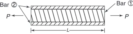
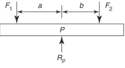
Problem 20. If the solid bar of Problem 19 did not suffer temperature change, but instead was subjected to a tensile axial forceP, as shown in Figure 1.14, determineσ1 and σ2.
L
P P
Bar 2 Bar 1
Figure 1.14 Compound bar under axial tension
There are two unknown forces in this bar, namely, F1 and F2; therefore, two simultaneous equations will be required.
The first of these simultaneous equations can be obtained by considering compatibility, i.e.
deflection of bar (1)=deflection of bar (2)
or δ1 =δ2
Butδ1=ε1Land δ2 =ε2L Therefore, ε1L=ε2L
or ε1 =ε2
Now,ε1= σ1 E1
andε2 = σ2 E2 Hence, σ1
E1 = σ2 E2
or σ1=
σ2E1 E2
(1.6)
The second simultaneous equation can be obtained by considering the equilibrium of the compound bar.
Let F1 =tensile force in bar (1) and F2 =tensile force in bar (2) Now, from equilibrium conditions
P =F1+F2
i.e. P =σ1A1+σ2A2 (1.7)
Substituting equation (1.6) into equation (1.7) gives:
P = σ2E1 E2
A1+σ2A2=σ2
E1A1 E2 +
A2
=σ2
A1E1+A2E2 E2
Rearranging gives: σ2=
PE2 (A1E1+A2E2)
(1.8)
and σ1=
PE1 (A1E1+A2E2)
(1.9)
N.B. IfP is a compressive force, then bothσ1 and σ2 will be compressive stresses (i.e. negative), and vice-versa ifP were tensile.
Problem 21. A concrete pillar, which is reinforced with steel rods, supports a compressive axial load of 2 MN.
(a) Determine stressesσ1 andσ2 given the following:
For the steel,A1 =4×10⁻³ m2 and E1=2×10¹¹ N/m2
For the concrete,A2=0.2 m2 and E2=2×10¹⁰ N/m2
(b) What percentage of the total load does the steel reinforcement take?
(a) From equation (1.9),
σ1= −
P E1
(A1E1+A2E2)
= − 2×106×2×1011
4×10−3×2×1011+0.2×2×1010
= − 4×10¹⁷
8×10⁸+40×108 =
4×10¹⁷
48×108
= 109
12 = −83.3×10
6
i.e.the stress in the steel,
σ1= −83.3 MPa (1.10)
From equation (1.8),
σ2= −
P E2
(A1E1+A2E2)
= − 2×106×2×1010
(4×10−3×2×1011+0.2×2×1010)
= − 4×10¹⁶
(8×10⁸+40×108)
= 4×10¹⁶ 48×108 =
108 12 = −8.3×10⁶
i.e.the stress in the concrete,
σ2 = −8.3 MPa (1.11)
(b) Force in the steel, F1 =σ1A1
= −83.3×106×4×10−3 =3.33×10⁵ N
Therefore,the percentage total load taken by the steel reinforcement
= F1
total axial load×100%
= 3.33×10⁵
2×106 ×100%=16.65% Problem 22. If the pillar of problem 21 were subjected to a temperature rise of 25°C, what would be the values of stresses σ1 andσ2?
Assume the coefficients of linear expansion are, for steel,α1=14×10−6/°C, and for concrete,α2 =12×10−6/°C.
Asα1 is larger thanα2, the effect of a temperature rise will cause the ‘thermal stresses’ in the steel to be compressive and those in the concrete to be tensile. From equation (1.5),the thermal stress in the steel,
σ1= −
(α1−α2)E1E2A2T (A1E1+A2E2)
= −
(14×10−6−12×10−6)×2×1011
×2×1010×0.2×25 48×108
= −40×1015
48×108 =0.833×10 7
=−8.33 MPa (1.12)
From equation (1.3), the thermal stress in the concrete,
σ2= σ1A1
A2 = −
(−8.33×106)×4×10−3 0.2
=0.167 MPa (1.13)
From equations (1.10) to (1.13):
σ1= −83.3−8.33=−91.63 MPa
Now try the following exercise
Exercise 5 Further problems on compound bars
1. Two layers of carbon fibre are stuck to each other, so that their fibres lie at 90° to each other, as shown in Figure 1.15. If a tensile force of 1 kN were applied to this two-layer compound bar, determine the stresses in each. For layer 1, E1 = 300 GPa and A1 =10 mm2; for layer 2, E2 =50 GPa andA2 =A1=10 mm2.
[σ1=85.71 MPa,σ2 =14.28 MPa]
Layer 1
Layer 2
P P
Figure 1.15 Carbon fibre layers
2. If the compound bar of Problem 1 were subjected to a temperature rise of 25°C, what would the resulting stresses be? Assume the coefficients of linear expan-sion are, for layer 1, α1 = 5×10⁻⁶/°C, and for layer 2, α2 =0.5×10⁻⁶/°C.
[σ1=80.89 MPa,σ2 =19.10 MPa]
Exercise 6 Short answer questions on the effects of forces on materials
1. Name three types of mechanical force that can act on a body.
2. What is a tensile force? Name two prac-tical examples of such a force.
3. What is a compressive force? Name two practical examples of such a force.
4. Define a shear force and name two prac-tical examples of such a force.
5. Define elasticity and state two examples of elastic materials.
7. Define plasticity and state two examples of plastic materials.
8. Define the limit of proportionality.
9. State Hooke’s law.
10. What is the difference between a ductile and a brittle material?
11. Define stress. What is the symbol used for (a) a tensile stress (b) a shear stress?
12. Strain is the ratio . . . . . . . . 13. The ratio stress
strain is called. . . .
14. State the units of (a) stress (b) strain (c) Young’s modulus of elasticity
15. Stiffness is the ratio . . . . . . . .
16. Sketch on the same axes a typical load/extension graph for a ductile and a brittle material.
17. Define (a) ductility (b) brittleness (c) malleability
18. Define rigidity modulus.
19. The new length L2 of a bar of length L1, of coefficient of linear expansionα, when subjected to a temperature rise T is: L2 =. . . .
20. The thermal strainεdue to a temperature riseT in material of coefficient of linear expansionα is given by:ε=. . . .
Exercise 7 Multi-choice questions on the effects of forces on materials (Answers on page 284)
1. The unit of strain is:
(a) pascals (b) metres
(c) dimension-less (d) newtons 2. The unit of stiffness is:
(a) newtons
(b) pascals
(c) newtons per metre
(d) dimension-less
3. The unit of Young’s modulus of elastic-ity is:
(a) Pascals (b) metres
(c) dimension-less (d) newtons 4. A wire is stretched 3 mm by a force of
exceeded, the force that will stretch the wire 5 mm is:
(a) 150 N (b) 250 N
(c) 90 N (d) 450 N
5. For the wire in question 4, the extension when the applied force is 450 N is:
(a) 1 mm (b) 3 mm
(c) 9 mm (d) 12 mm
6. Due to the forces acting, a horizontal beam is in:
(a) tension (b) compression
(c) shear
7. Due to forces acting, a pillar supporting a bridge is in:
(a) tension (b) compression
(c) shear
8. Which of the following statements is false?
(a) Elasticity is the ability of a material to return to its original dimensions after deformation by a load.
(b) Plasticity is the ability of a material to retain any deformation produced in it by a load.
(c) Ductility is the ability to be perma-nently stretched without fracturing.
(d) Brittleness is the lack of ductility and a brittle material has a long plastic stage.
9. A circular rod of cross-sectional area 100 mm2 has a tensile force of 100 kN
applied to it. The stress in the rod is:
(a) 1 MPa (b) 1 GPa
(c) 1 kPa (d) 100 MPa
10. A metal bar 5.0 m long extends by 0.05 mm when a tensile load is applied to it. The percentage strain is:
(a) 0.1 (b) 0.01
(c) 0.001 (d) 0.0001
An aluminium rod of length 1.0 m and cross-sectional area 500 mm2 is used to support a load of 5 kN which causes the rod to contract by 100 μm. For questions 11 to 13, select the correct answer from the following list:
(a) 100 MPa (b) 0.001 (c) 10 kPa
(d) 100 GPa (e) 0.01 (f) 10 MPa
(g) 10 GPa (h) 0.0001 (i) 10 Pa
11. The stress in the rod
12. The strain in the rod
13. Young’s modulus of elasticity
14. A compound bar of lengthLis subjected to a temperature rise of T. If α1 > α2, the strain in bar 1 will be:
(a) tensile (b) compressive
(c) zero (d)αT
15. For Problem 14, the stress in bar 2 will be:
(a) tensile (b) compressive
2
Tensile testing
At the end of this chapter you should be able to:
• describe a tensile test
• recognise from a tensile test the limit of proportionality, the elastic limit and the yield point
• plot a load/extension graph from given data • calculate from a load/extension graph, the modulus of elasticity, the yield stress, the ultimate tensile strength, percentage elongation and the percentage reduction in area
2.1
The tensile test
A tensile test is one in which a force is applied to a specimen of a material in increments and the corresponding extension of the specimen noted. The process may be continued until the specimen breaks into two parts and this is called testing to destruction. The testing is usually carried out using a universal testing machine that can apply either tensile or compressive forces to a specimen in small, accurately measured steps.British Standard 18gives the standard procedure for such a test. Test specimens of a material are made to standard shapes and sizes and two typical test pieces are shown in Figure 2.1. The results of a tensile test may be plotted on a load/extension graph and a typical graph for a mild steel specimen is shown in Figure 2.2.
(i) Between A and B is the region in which Hooke’s law applies and stress is directly proportional to strain. The gradient ofAB is used when determining Young’s modulus of elasticity (see Chapter 1).
(ii) Point B is the limit of proportionalityand is the point at which stress is no longer proportional to strain when a further load is applied.
Gauge length
Thickness
Width
(b) (a)
Diameter
Figure 2.1
A G
B
J
E
F
H C KD
Load
Permanent elongation
Extension 0
Figure 2.2
(iii) Point C is the elastic limit and a specimen loaded to this point will effectively return to its original length when the load is removed, i.e. there is negligible permanent extension.
(iv) PointD is called the yield pointand at this point there is a sudden extension to J, with no increase in load. The yield stress of the material is given by:
yield stress=
The yield stress gives an indication of the ductility of the material (see Chapter 1).
(v) For mild steel, the extension up to the point J is some 40 times larger than the extension up to the pointB.
(vi) Shortly after pointJ, the material strain hard-ens, where the slope of the load-extension curve is about 1/50th the slope of the curve from A to B, for materials such as mild steel.
(vii) Between points D and E extension takes place over the whole gauge length of the specimen.
(viii) Point E gives the maximum load which can be applied to the specimen and is used to determine the ultimate tensile strength (UTS) of the specimen (often just called the tensile strength)
UTS= maximum load original cross-sectional area
(ix) Between points E andF the cross-sectional area of the specimen decreases, usually about half way between the ends, and a waist or neckis formed before fracture.
Percentage reduction in area
=
(original cross-sectional area)
−(final cross-sectional area)
original cross-sectional area ×100% The percentage reduction in area provides information about the malleability of the material (see Chapter 1). The value of stress at point F is greater than at point E since although the load on the specimen is decreas-ing as the extension increases, the cross-sectional area is also reducing.
(x) At pointF the specimen fractures.
(xi) DistanceGH is called thepermanent elon-gationand
permanent elongation
=
increase in length during test to destruction
original length ×100% (xii) The point K is known as the upper yield
point. It occurs for constant load experi-ments, such as when a hydraulic tensile test-ing machine is used. It does not occur for
constant stain experiments, such as when a Hounsfield tensometer is used.
2.2
Worked problems on tensile testing
Problem 1. A tensile test is carried out on a mild steel specimen. The results are shown in the following table of values:
Load (kN) 0 10 23 32
Extension (mm) 0 0.023 0.053 0.074
Plot a graph of load against extension, and from the graph determine (a) the load at an extension of 0.04 mm, and (b) the extension corresponding to a load of 28 kN.
The load/extension graph is shown in Figure 2.3. From the graph:
0.01 0 4 8 12 16 17.2 20 24 28 32
0.02 0.03 0.04 0.05 0.06 0.07 0.08
Load
/kN
Extension / mm
Figure 2.3
(a) when the extension is 0.04 mm, the load is 17.2 kN
(b) when the load is 28 kN, the extension is 0.065 mm.
Load (kN) 0 8 19 29 36 Extension (mm) 0 0.015 0.038 0.060 0.072
The maximum load carried by the specimen is 50 kN and its length after fracture is 52 mm. Determine (a) the modulus of elasticity, (b) the ultimate tensile strength, (c) the percentage elongation of the mild steel.
The load/extension graph is shown in Figure 2.4.
0.01 0.02 0.03 0.04 0.05 0.06 0.07 0.08 0
10 20 25 30 40
A
Load
/kN
Extension / mm B
C
Figure 2.4
(a) Gradient of straight line is given by:
BC AC =
25000
0.05×10−3 =500×10 6 N/m
Young’s modulus of elasticity =(gradient of graph)
L A
, where
L=40 mm (gauge length) =0.040 m and area,
A=100 mm2=100×10−6 m2. Young’s modulus of elasticity
=(500×106)
0.040 100×10−6
=200×109 Pa=200 GPa
(b) Ultimate tensile strength
= maximum load
original cross-sectional area
= 50000 N
100×10−6 m2 =500×10 6 Pa
=500 MPa
(c) Percentage elongation
= increase in length original length ×100
= 52−40
40 ×100=
12
40 ×100=30%
Problem 3. The results of a tensile test are: Diameter of specimen 15 mm; gauge length 40 mm; load at limit of proportionality 85 kN; extension at limit of proportionality 0.075 mm; maximum load 120 kN; final length at point of fracture 55 mm.
Determine (a) Young’s modulus of elasticity, (b) the ultimate tensile strength, (c) the stress at the limit of proportionality, (d) the
percentage elongation.
(a) Young’s modulus of elasticity is given by:
E= stress strain =
F A x L
= F L
Ax
where the load at the limit of proportionality,
F=85 kN=85000 N,
L=gauge length=40 mm=0.040 m,
A=cross-sectional area= πd 2 4
= π(0.015)2
4 =0.0001767 m 2, and x =extension=0.075 mm=0.000075 m.
Hence, Young’s modulus of elasticity
E= F L Ax =
(85000)(0.040) (0.0001767)(0.000075)
(b) Ultimate tensile strength
= maximum load
original cross-sectional area
= 120000 0.0001767
=679×106 Pa=679 MPa
(c) Stress at limit of proportionality
= load at limit of proportionality cross-sectional area
= 85000
0.0001767=481×10
6 Pa=481 MPa
(d) Percentage elongation
= increase in length original length ×100
= (55−40)mm
40 mm ×100=37.5%
Now try the following exercise
Exercise 8 Further problems on tensile testing
1. What is a tensile test? Make a sketch of a typical load/extension graph for a mild steel specimen to the point of fracture and mark on the sketch the following: (a) the limit of proportionality, (b) the elastic limit, (c) the yield point.
2. In a tensile test on a zinc specimen of gauge length 100 mm and diameter 15 mm, a load of 100 kN produced an extension of 0.666 mm. Determine (a) the stress induced, (b) the strain, (c) Young’s modulus of elasticity.
[(a) 566 MPa (b) 0.00666 (c) 85 GPa]
3. The results of a tensile test are:
Diameter of specimen 20 mm, gauge length 50 mm, load at limit of propor-tionality 80 kN, extension at limit of pro-portionality 0.075 mm, maximum load 100 kN, and final length at point of frac-ture 60 mm.
Determine (a) Young’s modulus of elas-ticity, (b) the ultimate tensile strength, (c) the stress at the limit of proportion-ality, (d) the percentage elongation.
(a) 169.8 GPa (b) 318.3 MPa
(c) 254.6 MPa (d) 20%
2.3
Further worked problems on
tensile testing
Problem 4. A rectangular zinc specimen is subjected to a tensile test and the data from the test is shown below. Width of specimen 40 mm; breadth of specimen 2.5 mm; gauge length 120 mm.
Load (kN)
10 17 25 30 35 37.5 38.5 37 34 32 Extension (mm)
0.15 0.25 0.35 0.55 1.00 1.50 2.50 3.50 4.50 5.00 Fracture occurs when the extension is 5.0 mm and the maximum load recorded is 38.5 kN.
Plot the load/extension graph and hence determine (a) the stress at the limit of proportionality, (b) Young’s modulus of elasticity, (c) the ultimate tensile strength, (d) the percentage elongation, (e) the stress at a strain of 0.01, (f) the extension at a stress of 200 MPa.
A load/extension graph is shown in Figure 2.5.
(a) The limit of proportionality occurs at point P on the graph, where the initial gradient of the graph starts to change. This point has a load value of 26.5 kN.
Cross-sectional area of specimen
=40 mm×2.5 mm=100 mm2 =100×10−6 m2.
Stress at the limit of proportionality is given by:
σ =force area =