Int. J. Electrochem. Sci., 7 (2012) 2811 - 2831
International Journal of
ELECTROCHEMICAL
SCIENCE
www.electrochemsci.orgEffect of Air Plasma Sprays Parameters on Coating
Performance in Zirconia–Based Thermal Barrier Coatings
Mohamed S. Morsi1,*, Soha A. Abd El Gwad1, Madiha. A. Shoeib2, Khalid. F. Ahmed3
1
Chemistry Department, Faculty of Science, Cairo University, Giza, Egypt
2
Corrosion Control and Surface protection Department, CMRDI.Cairo, Egypt
3
Chemistry Department, Engine Factory, AOI, Cairo, Egypt .
*
E-mail: dr_m_saber@live.com
Received: 6 February 2012 / Accepted: 12 March 2012 / Published: 1 April 2012
Advanced ceramic multilayered coatings are commonly used as protective coatings for engine metal components, where, aerospace gas turbine engines are now designed such that the heat resistant super alloys operate at temperature very close to their melting, so current strategies for performance improvement are centered on thermal barrier coatings. The main focus of this work is to study the effect of different parameters of air plasma spraying technique for various thermal barrier coatings comprised of zirconia stabilized with magnesia top coat and nickel-aluminum bond coat as well as their properties with those obtained using reference techniques. The deviations of the parameters from the optimum conditions are discussed. The investigation shows that: the deviation of the plasma spray parameters from the optimum conditions led to create a poor contact between the bond coat and the Ni-base-super alloy substrate, increase of the cracks resulting from the relaxation of residual stresses in the planer direction (open porosity), increase of the voids resulting from poor deformation of partially melted particle (few micrometer void), and present of the un-melted particles. The conclusions of this experimental study are in good agreement with theoretical predictions resulting from a sensitivity analysis reported in a previous study.
Keywords: Thermal barrier coating, air plasma spray, heat treatment, thermal expansion coefficient, thermal conductivity, zirconia stabilized with magnesia.
1. INTRODUCTION
the temperature regime in which a component can operate [3, 4]. A typical application is in gas turbine engine which are now designed such that nickel super alloy components operate at temperatures very close to their melting points, so current strategies for performance improvements are concentrated on thermal barrier coatings [5-8].
Thermal barrier coating systems on super alloys combine a thermal insulating zirconia top coat, which has a relatively low thermal conductivity and large thermal expansion coefficient compared with other technological ceramic, with a metallic bond coat that protects the substrate from both oxidation ( usually with the development of stabilized protective thin layer) and hot corrosion when operated at high temperature.
For ease and economy of fabrication, a graded thermal barrier coatings is comprised of finite number of layers, each have a certain ceramic-bond coat alloy proportions. Several studies have addressed the thermal fracture and failure mechanisms in pure ceramic thermal barrier coatings [9-17].
The zironica is excellent refractory owing to its high melting point (about 2680 0C), its low coefficient of expansion and thermal conductivity, and its resistance to chemical action so it's used as a raw material for TBC system.
Pure ZrO2 has three polymorphs. Monoclinic zirconia (m-ZrO2) is stable up to 1170oC, where it
transforms to tetragonal zirconia (t.Zr O2), the later tetragonal zirconia changed into cubic zirconia (c-ZrO2) at 2370oC and finally zirconia melt at 2680oC [18].
The magnesia-zirconia system which has already become established as plasma sprays TBC in high temperature aero engine application. Magnesia-zirconia are nevertheless considered the best prospective starting materials for industrial gas turbine, TBC and the test programmed was therefore concentrated on modifying zirconia-stabilized with magnesia to give optimum properties. Zirconia-stabilized with magnesia coating have been used in aircraft gas turbines as thermal barriers in combustor cans for several years. They have more recently been utilized on high pressure nozzle guide vane plat forms and there is much interest in coating the pressure surfaces of turbine blades. Plasma sprayed magnesia stabilized with zirconia coatings consist of porous phase material attached to a substrate by an intermediate bond coat. The porous nature of the coating greatly enhances thermal and crack resistance.
There are many spray parameters that affects the properties of the sprayed plasma coating, the most common control parameters are: Chemical compositions, phase structure and crystal size of the powder input, substrate temperature, plasma gas, plasma torch, powder feeder (.e.g. grain size chemical and phase composition, shape, internal porosity (correlated with apparent density) and flow-ability), spray angle, and finally spray distance.
The properties of TBC have to be suited to the final application, with some specific design criteria being related directly to the powder. The material must be designed to give optimum thermal insulation coupled with the required engineering properties, to provide physical performance with visible economic benefits.
microscope at different conditional plasma parameters with hardness, tensile strength and porosity. Also, a comparative study for corrosion resistance of coated and uncoated substrate was done.
2. MATERIALS AND EXPERIMENTAL METHODS
2.1. Apparatus and Process Description
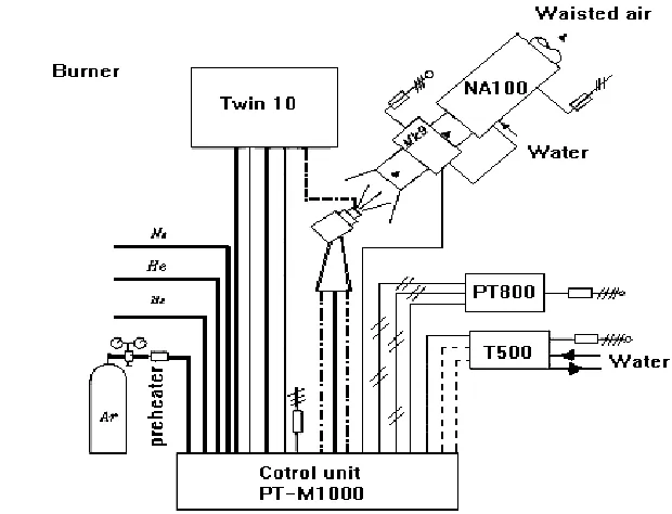
PLASMA-TECHNIK AG M-1000 apparatus, Figure (1) is used for plasma spraying with improved and developed plasma torches and auxiliary equipment for the spraying of aerospace components. It comprises: power source (PT-800), control unit (PT-M1000), plasma torch- (F4), powder feed unit (TWIN- 10), water cooler system (T-500) and holding device for the work piece, in addition to dust separator (MK-9) and wet separator (NA-100).
The direct current arc, energized from the power source using high frequency sparking ionizes the gas flowing through the torch. Argon gas is used for arc initiation (easily ionized), an auxiliary gas is normally added, such as H2 dissociate at high temperatures before ionizing, therefore, it exhibit a
higher energy (for a certain temperature) than gases such as Ar or He. The mixture of electrons, ions and neutral gas particles is the plasma i.e. a gas with an extremely high temperature (104-3x10⁴ k) and heat capacity. The increase in temperature causes the plasma to exit from the anode nozzle with a high velocity. The sprayed powder is introduced into hot and fast plasma using an injector; the particles are heated, accelerated and the powder particles become molten. The particles impact the surface to be coated with a high kinetic energy forming a laminar coating. Plasma spray coating is produced by successive impacts of accelerated particles on the substrate or previously deposited layers. The conditions of both particles (temperature, velocity and size) and substrate (temperature, chemistry, roughness, etc) determine the particle spreading and solidification. In our investigation the plasma spraying gas is a mixture of pure Ar gas and small addition of H2. Argon is a primary gas it cause
rapid heat transfer rate between a plasma jet flame and the heated object [19], in addition it protects powder particles against oxidation while hydrogen is an auxiliary gas to increase plasma voltage; which lead to increase in plasma enthalpy and heat transfer rates [20] therefore, higher plasma gas heat capacity resulted. The purity level of the gases used plasma spraying is 99.997 %; it must be observed at all times of investigation. The key parameters controlling the thermo-mechanical properties of plasma sprayed are the heat and momentum transfers between the plasma jets and the injected particles. These, depends strongly on the plasma isotherms lengths and diameters which in turn controlled by the different spray parameters of control unit PT-M 1000, powder feed (TWIN-10) and plasma torch (F4).
2.2. Testing materials
material zirconia stabilized magnesia (ZrO2-20 wt. % MgO), AMDRY 333 of 0.3-0.8 mm thickness with an agglomerated and sintered morphology was chosen. The metallic bond coating material
powder was (Ni-5wt % Al), AMDRY 956 of 0.05 mm as a minimum thickness. Table (1), shows characteristics for plasma coating systems.
To improve the mechanical adhesion of the coating and induces compressive stresses into the substrate, the substrate must be roughened into a surface roughness value of 10 ± 2.5 μm using automatic adjustable device. The phase analysis and the quantitative identification of the base material (substrate) has analyzed by using X- ray diffraction (XRD) and spectrum label technique (elector diffraction X- ray) EDX respectively.
2.3. Surface investigation
Metallographic examinations of the coat have been investigated by using scanning electron microscopic (SEM). Cross-sections were made in the plane perpendicular to the treated surface, then encapsulated and polished.
Tensile bonding measurement takes place by using ASTM 633- 96 or DIN 50160 standards. Bonding of sprayed coating is measured by using a traction machine. The installation must allow carrying out the test perpendicular to the coated surface, and the load application rate is constant, between 0.8 and 1.2 mm/ min. Bond strength value or stress to rupture is the ratio between the rupture load and the bonding surface, this is expressed in Mega-Pascal (M Pa). For coating with a single layer, thicknesses required are 150 μm to 200 μm.
Particle velocity and surface temperature measurements, especially in the field of particle diagnostics, many systems are available to measure particle velocity and surface temperature on-line [21-24]. In this study, a commercially available DPV-2000 system made by TECNAR Canada was used enables the on-line measurement of surface temperature, velocity and diameter of single particles in a spray plum by the principle of two-wavelength pyrometry [24,25].
Porosity and pore distribution were tested with commercially available mercury intrusion porosity-meter [26]. The method consists of evacuating the sample and immersing in mercury at low pressure, mercury is then pressurized and the series of pressures and corresponding volumes of intruded mercury is determined. The corrosion rate as well as the corrosion behavior of specimens was determined usinglinear polarization and potentiodynamic techniques, the tests were conducted by sweeping the potential with scan rate of 1mv/s from -100 mv below Ecorr to 1000mv above Ecorr before and after plasma thermal spray technique.
3. RESULTS AND DISCUSSION
before impinging on substrate (super-alloy) surface. The change of H2 gas flow rate and consequently
H2-content in the plasma spraying gas plays a serious and important effect on plasma voltage for Ni-Al
bond coat and zirconia-magnesia top coat. Figure (2), represents the rapid variation of plasma voltage through increasing of H2-content in plasma gas, where, the plasma voltage rises from 27 volts for pure
Ar plasma gas to 68 volts when H2 gas flow rate is 9.5 L/min and H2-content in Ar-H2 mixture is equal
to 20.2% for deposition of Ni-Al bond coat, while it reaches to a value of 72 volts for H2 gas rate flow
13 L/min and H2-content of 27.6% in plasma gas mixture for deposition of zirconia-magnesia top coat.
It is clear that H2 gas flow rate and consequently H2-content in plasma gas mixture plays an important
role for increasing the mean integrated thermal conductivity, although H-ionization potential is lower than Ar-ionization potential by about 2.0 electron volts. The higher plasma voltage values are attributed to enhanced conductive thermal looses at temperatures higher than 4000 k which lead to an increase of the electric field strength.
3.1. Influence of the plasma spray parameters on coating performances of Ni-Al bond coat:
The most common of AMDRY 965 powders are basic aluminizes that can be diffused into a substrate or base parent metal to form an external coating of metal aluminize. As aluminized is driven inward, it combines with key base metal element to form complex inter-metallic coating that is primarily Ni-Al. Optimization of plasma sprays parameters is very importance for the deposition of high dense coatings with fine microstructure, low porosity and continuous interface between the Ni-Al bond coat and the substrate without separation and voids, which indicate excellent wetting and adhesion between the two constituents. The optimum conditions of the plasma spray parameters are H2 gas flow rate 9.5 L/min and total flow rate 56.5 L/min with H2-content 20.2% of, plasma current
450 A, plasma voltage 68V, injector angle 90o and spraying distance 130 mm with maximum substrate temperature 140oC. The deviation from the optimum conditions of these parameters on the coating performances and mechanical properties were studied, while keeping constant all other spray parameters of control unit PT-M 1000, powder feed (TWIN-10) and plasma torch (F4). A comparison of mechanical properties for different TBC at different spray conditions in terms of corresponding porosity is given in table (2). Figures(3A&3B) show metallographic image analysis of sprayed AMDRY 956 bond coat with different spray parameters. SEM images show the following possible defects., 1► poor contact to the Ni-base-super alloy substrate, 2► crack resulting from the relaxation of residual stresses in the planer direction (open porosity), 3► void resulting from poor deformation of partially melted particle, 4►un-melted particle.
According to the results obtained for hardness, tensile bond strength and porosity one can deduce; that highest values for hardness and tensile bond strength are 190 HV3 and 35M Pa
[image:6.596.147.457.135.372.2]
(NiCr20TiAl), such reduction in (Cr) from 20 wt % into 16 wt % and increase in other refractory metal (Ni) from 75 wt % into 82.15 wt %.
[image:6.596.98.470.431.585.2]Figure 1. Systematic diagram of (Plasma-Technique AG M-1000).
Figure 2. Effect of H2-content % on plasma voltage for Ni - Al bond coat, and Zirconia top coat.
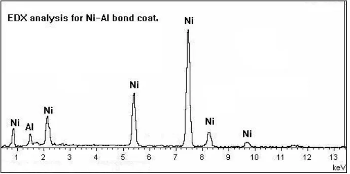
The electron dispersive x-ray (EDX) analysis was examined on cross-section samples taken at different positions for each coating was measured. The analysis was taken at the diffused layer (coating/substrate interface) and at the bond coat (Ni-Al). The EDX analysis of specimens is shown in Figure (4) and table (3). By decreasing the H2 gas flow rate from 9.5 L/min to 8.6 L /min i.e.
decreasing H2-content from 20.2% to 18.2% ,the plasma voltage decreased from 68 V to 60 V that
unmelted particles, cracks and void resulted, photo S1 (Fig.3A). Increasing of the plasma current from
the deposition efficiency decreased. The least tensile bond strength 25 MPa and highest porosity 9% obtained at plasma current 400 A. The coating was shown defects. open porosity, voids and un-melted particles, Photos S3 (Fig.3B). The deviation of injector angle from 90o to 35o leads to decrease in the
number of droplet which impact normally that poor contact, voids and unmelted particles resulted , photo S4 (Fig.3B).On decreasing the spraying distance from 130 mm to 75 mm, the substrate
temperature increased, also, wrongly placed of cooling air jets leads to increase in the substrate temperature, deviation occurs for the droplet during flight for long distance, photos S2 and S5 Fig.(3A)
and Fig.(3B) respectively.
(x500) So (x200) H2 gas flow rate 9.5 L/min and total flow
rate 56.5 L/min with H2-content 20.2% of, plasma current 450 A, plasma voltage 68V,
injector angle 90o, maximum substrate temperature 140oC and spraying distance 130 mm.
S1 S2
H2 gas flow rate 8.6 L /min i.e. H2-content Spraying distance 75mm,
18.2% , plasma voltage 60 V substrate temperature 400°C
Figure 3A. Back scattered SEM image for cross section view of Nickel - Aluminum (bond coat) coating sprayed with the optimum and deviated condition.
Ni-Al bond coat
Sharp edge
Ni-base substrate
substrate Diffusion between
substrate and bond coat
[image:7.596.91.502.228.720.2]
S3A S3B
400A 500A
S4 S5
Injection angle 35° wrong placed of cooling air jet
Figure 3B. Back scattered SEM image for cross section view of Nickel - Aluminum (bon coat) coating sprayed with the optimum and deviated condition.
3 4
2 3
[image:8.596.124.470.592.768.2][image:9.596.43.554.346.470.2]
Figure 4. EDX patterns taken, at the interface (i.e. between the bond coat and the substrate), also at the bond coat.
Table 1. Characteristics for plasma coating systems
Powder Characteristics Coating Characteristics
Spray Powder Grain Size (μm) Allowed Thickness (mm) Micro-hardness (HV3) Tensile strength (M Pa) Porosity (%) Density (g/cc) Operation Temp. (°C) AMDRY 956 Bond coat
45~90 0.05~1 Min 180 Min 35 Max 2 Min 7.43 Max 870
AMDRY 333 Top coat
10~45 0.1~0.5 Min 200 Min 22 Max 15 Min 4.28 Max 1000
Table 2. Mechanical properties of the Ni-Al bond coat for deviated conditions
Specimen
Number Deviated Parameter
Tensile Strength (M Pa) Hardness (HV3) Porosity (%) Thick-ness ( μm)
So Optimum Conditions 35 190 2 250
S1
H2 gas flow rate and % content 8.6 L/min, 18.2 %
Plasma voltage 60 V
150 27 6 160
S2A
S2B
Plasma current, Particle speed and temperature
400 A, 400 m/s, 1420°C 500 A, 500 m/s, 1490°C
130 155 25 31.6 9 1.5 125 240 S3
Injection Angle, 35°
165 33 5.5 200
S4
Wrong cooling, max. substrate temperature
350°C 157 30
7
175
S5
Spraying distance and substrate temperature
[image:9.596.39.561.521.750.2]
Table 3. EDX results of the diffused layer (inner the coating interface between the bond coat and the substrate) and the bond coat layer (outer the coating interface).
Position of analysis
Element (wt %)
Ni Al Cr Ti Si O Mn
At outer the coating interface
95 5 -- -- -- --
At inner the coating interface
82.15 1.2 16 0.4 0.9 0.15 0.1
3.2. Influence of the plasma spray parameters on coating performance of zirconia-magnesia top coating:
AMDRY 956 is an aggregate powder comprised of nickel spheres surrounded by minute particles of aluminum. When thermally sprayed, the aluminum and nickel react and self bond to a clean sand blast roughened metallic surface. Hence it is particularly suitable for use as a bond coat or pre-coat to enhance the adhesion of less adherent zirconia coating material. As a top coating material zirconia stabilized magnesia (ZrO2-20 wt% MgO (AMDRY 333) powder thermally sprayed as a top coating. The highest surface hardness value of 200 HV3 and tensile bond strength value of 22 MPa,
which corresponding to a porosity value of 9.8 % for zirconia (top coat), are obtained at the optimum conditions of the plasma spray parameters for (ZrO2-MgO) top coat which are H2 gas flow rate 13
L/min and total flow rate 60.5 L/min with H2-content 27.6% of, plasma current 630 A, plasma voltage
72V, injector angle 90oand spraying distance 90 mm ,with maximum substrate temperature 150oC. As previously estimated the deviation of these parameters from the optimum conditions leads to serious defects and unrequired mechanical properties. By keeping constant all other spray parameters of control unit PT-M 1000, powder feed (TWIN-10) and plasma torch (F4), the effect of deviated parameters on surface morphology and mechanical properties for different TBC were studied. Table (4) summarizes mechanical properties for different TBC at different spray conditions in terms of corresponding porosity, while Figures (5-7) show the SEM image for cross- section view of zirconia stabilized with magnesia (top coat) coating on nickel-aluminum (bond coat) sprayed with different conditions. The following possible defects are observed. 1► poor contact to previous coating e.g. bond-coat, interface of plasma sprayed at different conditions is not sharp; 2► crack resulting from the relaxation of residual stresses in the planar direction (open porosity); 3► void resulting from poor deformation of partially melted particle (few micrometer void); 4► Large crystals (i.e. the deposition of high dense coating with fine microstructure decreases) 5► dislocation indicates the extended zirconia. The electrochemical parameters: corrosion potential (Ecorr), corrosion current (Icorr),
polarization resistance (RP), and corrosion rate (CR) derived from linear polarization experiments for
Ni-base supper alloy substrate specimens to corrosion rates of same substrates coated with zirconia top coat and sub-layer Ni-Al bond coat at different conditions. According to the results obtained, one can detect the following: For plasma gas, by introducing plasma gas as pure Argon only, the hardness decreases from 200 HV3 to 115 HV3 which is less than expected one due to low plasma voltage
(27.6V) which lead to un-melted phases and de-laminations, in addition the intensity of non bonded particles of zirconia increased. In otherwise, the hardness of the coating decreases with decreasing plasma energy [27]. Argon ions are heavier than hydrogen ions, so, we must expect its responsibility for particle acceleration, this lead to a worse melting behavior for powder particles, consequently, lower deposition efficiency and lower coating thickness obtained, also, in absence of H2 the flam
temperature decreased and lower energy input obtained that lead to increase in solidification rate. As a fact lower-heated droplets has larger viscosity that it is not easily flattened that a variations in the wetting of the droplet on the substrate may be occurs, which could influence the final shape [28]. Figure (5) shows micro-photos ("So) which is for optimized spray parameter conditions, the coatings
are very sharp and distinct, that the corrosion rate of the Ni-base super alloy substrate was largely decreased through plasma spraying zirconia coating at optimum condition for specimen ("So); the
efficiency of corrosion inhibition was 93%. Figure (6) Shows the micro-photo ("S1) which is for pure
Ar-gas at 47 L / min. where many defects observed: poor contact to the previous coating, void
resulting from poor deformation of partially melted particle and large crystals. . For plasma current; by increasing the plasma current from 630A to higher value 700A or
decreasing it to lower value 560A, the particle velocity increased from 280 m/s to 310 m/s or it decreased to 260 m/s respectively. That leads to higher particle surface temperature and higher plasma power at higher currents consequently worse melting of particle powder obtained. At lower currents plasma power lowered much, which leads to un-melted phase. Generally, the pumping effect decreases as the plasma current decreases [29]. It is clear in both cases the deposition efficiency decreased as well as thickness. Therefore, increasing of the plasma current to higher value 700A or decreasing it to lower value 560 A, the hardness decreases from 200 HV3 to 190 HV3 and 125 HV3 respectively. The
porosity is not affected much by increasing of the plasma current, but increased from 9 % to 12.9 % as the plasma current decreased to 560 A. This may refer to the fine microstructure of high dense coating becomes lower i.e. increasing of the crack resulting from the relaxation of residual stresses in the planar direction, increasing of the voids resulting from poor deformation of partially melted particle and the deposition of high dense coating with fine microstructure decreases. This explains the highest corrosion rate with lower efficiency less than 6% for specimen "S2A. The microstructure of sprayed
zirconia coatings at different plasma currents were shown in Fig. (6). with different plasma currents "S2A at 700 A and "S2B at 560A respectively.
For the injection angle; as the injector angle decreases from 90° to the lower value of 600, the hardness decreased from 200 to 187 HV3 and the porosity increased from 9.8 % to 13.8 %. This may
be referred to the poor contact to previous coating at interface, also, plasma sprayed at different conditions is not sharp and increase the voids resulting from poor deformation of partially melted particle. The micro photo "S3 in figure (6), shows defects of such conditions.
work piece, type of plasma gas, amount of plasma gas, the amount of powder, and heat energy leaving the plasma torch. The preheat substrate temperature has effect on the morphology of the droplet (splat) and the properties of the deposits. The change of the mounting of the coating air jets from 45° to 10° is resulting of increasing of the substrate temperature from 150°C to 400°C which lead to increase of the voids resulting from poor deformation of partially melted particle (few micrometer void), decrease of the deposition of high dense coating with fine microstructure and increase of the dislocation which indicates the extended of zirconia. The amount of the oxide phases were increased and thermal expansion decreased [30]. The microstructure (cross-section) of sprayed zirconia p coat) with different substrate temperature was show in figure. (7), photo "S4.
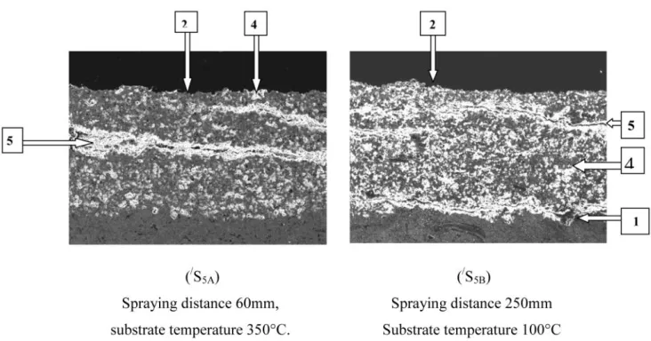
Injection distance; the spray distance affects the droplet temperature and thus the properties of spray coatings. Then the microstructures of sprayed particles are changed. The effect of spray distance on splat morphology, adhesion, and microstructure were examined and given in table (4), and figure. (7) Photos /S5A & /S5B. . As the spray distance increases the number of droplets which impact normally
decrease because deviation occurs for the droplet during flight for a long distance and the hardness value decreased, also the atmospheric oxygen incorporated with splats during impinging affect the properties of the coating because they create a kind of stress points. By increasing the spraying distance from 90mm to 250m, the hardness decreases from 200 HV3 to 110 HV3. The deviation of the
spray distance from the optimum condition leads to increase the porosity, pullout, un-melted particles and de-laminations, that leads to lower corrosion efficiency (<6%) for the specimens /S5B due to long
spraying distance and less Vickers Hardness (110 HV3). At small spraying distance; the substrate
exhibits the highest temperature that the temperature increased from 140 to 350 and the droplets have the highest velocity and droplet impinging on close substrate. By decreasing the spraying distance from 90mm to 60mm the hardness decreases from 200 HV3 to 190 HV3. The decreased porosity of
coatings caused by shorter distance between the nozzle and the sprayed surface results in their lower quality due to higher plasma temperature causing super heating effect on the substrate..
3.3. Effect of crystal structure on coating performance
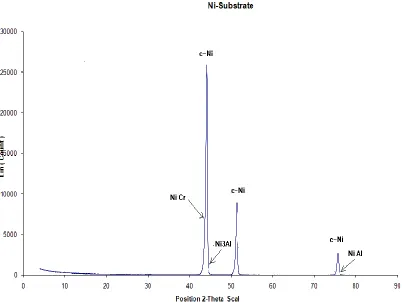
An analysis was used for the comparison of x-ray diffraction results of Ni-base substrate material, feed stock powder and as sprayed coatings. There are many kinds of unit cells which can be formed by the translational operation for coating system.
Figure (13) shows the XRD patterns of the feed stock powder which consists of some amorphous phase, while the as sprayed coatings have a well crystallized material and no amorphous phase is present any more. The substrate material contains a mixture of face cubic center Ni, Ni Cr, Ni Al, and Ni3Al phases.
Ni-Al (AMDRY 956) powder contain a mixture of c-Ni, c -Al, Ni3Al and Ni Al phases. Since
coating of metal aluminide. A part of this aluminide phase oxidizes during air plasma spraying to form a tenacious Al2O3 (and NiO) phases as a protective surface scale.
Pure zirconia (i.e. non-stabilized zirconia) exhibits the following polymorphic phase transformations:
(m-ZrO2) (t-ZrO2) (c-ZrO2).
The phase transition between the monoclinic and tetragonal phases is accompanied with a weight change of about 3.4 %, it is difficult to obtain a stable sintered body (i.e. t-ZrO2).
Since the ionic radius of Zr4+ is 0.82 0A is rather smaller than that of 8 fold coordination of ideal ionic of octahedral sites in fluorite structure (1.02 0A), so the structure of pure ZrO2 is distorted
(i.e. has un equal ZrO2 distances) and then not stable. In order to stabilize the cubohydral coordination
(distorted tetragonal structure) at a wide range of temperatures by substituting the Zr4+ sites with Mg2+ (0.66 0A).
Table 4. Mechanical properties of the zirconia stabilized with magnesia (top coat) for deviated conditions.
Specimen
Number Deviated Parameter
Tensile Bond Strength (M Pa) Hard- ness (HV3) Poro- sity (%) Thick-ness ( μm)
"So Optimum Conditions 22 200 9.8 230
"S1
gas flow rate
pure Ar gas 47 L/min, Plasma voltage 27 V
12 115 18.8 135
"S2A
"S2B
Plasma current, Particle speed and temperature
560 A, 260 m/s, 2589°C 700 A, 310 m/s, 2780°C
13 12 125 190 12.5 9 175 190 "S3 Injection Angle
60° 20 187 13.8 190
"S4
Wrong cooling, max. substrate
temperature 400°C 18.2 170
12.6
180
"S5A
"S5B
Spraying distance and substrate temperature
60 mm, 350°C 200 mm,100°C 20.8 15 190 110 12 18 180 175
1000oC 2370oC
[image:13.596.80.518.394.722.2]
These doped ZrO2 are called stabilized zirconia. Since the structure with anions in cubic center
phase and cations all resulting octahedral interstices occurs for MgO, and is commonly known as the rock salt structure. MgO is the only alkaline earth oxide which has octahedral coordination. Because of the spherical symmetry of oxide ions (O2-), these ions tend to form a stable structure which is tetragonal. In other words zirconia stabilized with magnesia is utilized to eliminate dimensional which occur due to allotropic transformations of the zirconia at specific critical temperature ranges.
[image:14.596.74.544.214.649.2]
ZrO2-MgO (AMDRY 333) powder contains a mixture of c-MgO; m-ZrO2, hexagonal
magnesium zirconium oxide phase (h-Mrg2Zr5O12) and they are results of the powder manufacturing
[image:15.596.68.540.165.707.2]technique. Rapid solidification and rapid cooling are the phenomena that occur after the impact of the particle with the previously deposited coating. Meta-stable structure and amorphous solid solutions are frequently observed, particularly in ceramic bulk materials.
These phenomena may result in the example is the formation of /t-ZrO2 phase (being
[image:16.596.115.481.305.497.2]meta-stable at room temperature) while air plasma spraying the zirconia stabilized with magnesia.
[image:16.596.44.554.601.745.2]Figure 7. SEM image for zirconia top coating on Ni-Al (bond coat) at different spraying distance and at wrongly placed cooling applied.
Table 5. Results of linear polarization experiments.
Specimen No. Ecorr (V)
Rp
(Ohm. cm2 X103)
Icorr (μA/Cm2)
Corrosion rate (mpy)
Efficiency (%)
substrate - 0.297 8.416 3.2906 0.97832 ----
"S0 - 0.237 185.8 0.22988 0.06834 93.01 %
"S1 - 0.290 54.58 2.11229 0.62798 35.8 %
"S2A - 0.323 8.648 3.2024 0.9521 2.6 %
"S2B - 0.231 18.67 2.2877 0.6813 30.3 %
"S3 - 0.266 13.91 3.0705 0.9128 6.6 %
"S4 - 0.477 8.661 3.1976 0.9506 2.8 %
"S5A - 0.469 148 1.8712 0.556 43.1 %
"S5B - 0.461 8.541 3.2425 0.964 1.4 %
[image:17.596.68.470.78.380.2]
Figure 8D. XRD patterns forstabilized ZrO2 with MgO powder & typical as deposit
4. CONCLUSIONS
A number of new coating methods have evolved and older methods were refined. New analytical tools are introduced. The development and evaluation of coatings are expensive and there is now a need, more than ever, to conserve resources, optimize test programmed and for a greater coordination dissemination of information.
In this study, The TBC system was investigated using several processes to conclude the influence of plasma spray parameters on the coating performance, from the obtained data, discussion and interpretation of the results, it could be concluded that:
1. The total porosity of the APS coating decreases as the hydrogen flow rate increases.
2. Argon was mainly responsible for accelerating the powder particles, not hydrogen flow rate. The higher particle velocity resulted in a worse melting behavior of the powder due to the shorter dwell time, leading to a lower coating thickness, namely a lower deposition efficiency of the powder. 3. The plasma current play a very important role with the increase of the pumping effect led to an
increase in the particle velocity as well as in the particle surface temperature, while the decrease in the plasma power from the optimum conditions led to a decrease in the deposition efficiency and an increase in the porosity.
4. As the injection angle decreases (or as the injection distance increases) led to increase the porosity, decrease the droplet temperature and decrease the number of droplets which impact normally. 5. It is noteworthy that amorphous microcrystalline, and meta-stable phase are commonly observed in
plasma sprayed materials due to the high rate (rapid solidification and rapid cooling) that are inherent in this process.
ACKNOWLEDGENMENT
The authors are grateful to all staff members of the Central Metallurgical Research and Development Institute (CMRDI) for their help during technical assistance and data analysis.
References
1. P. Vincenzini, Industr. Ceram. 10 (1990) 113.
2. J.T. DeMasi-Marcin and D.K. Gupta, Surf. Coat. Technol. 68-69 (1994) 1. 3. T.C. Mc Geary and J.M. Koffshey, Met. Progr. 1965.
4. M.L: Thrope and H.J. Richter, J. Thermal Spray Technol., 2(1992)161. 5. R.A Miller, J. Therm. Spray Technol. 6 (1997) 35
6. W. Beele, G. Marijnisen and A. van Lieshout, Surf. Coat. Technol. 121 (1999) 61, 52 (2000) 28 . 7. J.R. Nicholls, J. Met. 52 (2000) 28..
8. E.A.G. Shillington and D.R. Clarke, Acta Mater 47 (1999) 1297 .
9. Y.R. Takeuchi and K. Kokini, ASME Trans. J. Eng. Gas Turbines Power 116 (1994) 266. 10.K. Kokini and Y.R. Takeuchi, Mater. Sci. Eng. A 189 (1994) 301.
11.K. Kokini, B.D.and Coulees, Compos. Eng. 5-7 (1995) 865. 12.K. Kokini and Y.R. Takeuchi, Fracture Mech. 25 (1995) 177.
13.B.D. Coulees and K. Kokini, ASME Trans. J. Eng. Mater. Technol. 118 (4), (1996) 522. 14.K. Kokini and M.Case, ASME Trans. J. Eng. Mater. Technol. 119 (1997) 148.
15.Y.R. Takeuchi, J. K. Kokini, Thermal Stresses 21 (7), (1998) 715.
16.B.D. Choules K. Kokini, T.A. Taylor, Surf. Coat. Technol. 106 (1998) 23.. 17.B.D. Choules, K. Kokini, T.A. Taylor, Mater. Sci. Eng. A 299 (2001) 296.
18.E. Ryshkowitch, and D.W Richardson, Oxide ceramics, Second edition, Academic press Inc., 1985,
19.Giacobbe, F.W., High Temperature Technology, 8(1), (1990).
20.Milewski, 1973, Vinoyo et al., 1985b, Rangaswamy and Herman, 1986.
21.E. Hamalainen, J. Vattulainen, T. Alahautala, T. Mantyla, (2001) proceedings of ITSC 2001, Singapore, Singapore, PP.
22.D. Landes, T.V. Streibel, J. Zierhut, (2002) Proceedings of ITSC 2002, Essen, Germany, 2002, pp. 45.
23.P. Bertrand, I. Smurov, M. Ignatiev, (2002) Proceedings of ITSC 2002, Essen, Germany, 2002, pp. 66.
24.L. Leblanc, p. Gougeon, C. Moureau,(1997) Proccedings of UTSC, Indianapolis, USA, 1997, pp. 567.
25.P Gourgeon, C. Moureau, M. Lamontagne, V. Lacasse, G. Vaudreuil, P. Cielo, (1994) Proccedingnes NTSC, Boston, 1994, pp. 431- 437.
26.Whittemore, O. J. Mercury porosimetry of ceramic. Powder Technology, 29, (1981) 167- 175. . 27.Gao Y., Xu. Yan, Z., Xin, G. Surface coatings technology 154 (2-3), 2002 189-193.
28.A., M. Worthington study of splashes, Macmillan, 1963.
29.M. Brossa, E. Pfender, Plasma Chemistry, Plasma processing 8 (1) 75 (1988). 30.Sarikaya, O. Materials and design, 26 (1), (2005) 53- 57.