Article
The Analysis and Control of Zero-Sequence
Components in a Transformerless Back-To-Back
(BTB) System Using Modular Multilevel Cascade
Converters for Power Distribution Systems
Pracha Khamphakdi
Department of Electrical and Electronic Engineering, Faculty of Engineering, Ubon Ratchathani University, Ubon Ratchathani 34190, Thailand
E-mail: [email protected]
Abstract. This paper provides an intensive discussion on analysis and simulation of a back-to-back (BTB) system based on double-star chopper cells (MMCCs-DSCCs). It is installed between two 6.6-kV power distribution feeders. It is also referred to as the so-called “loop power flow controller.” A three-phase 200-V, 10-kW, 50-Hz BTB transformerless system is simulated to verify its operating principles, modelling, and performance of zero-sequence current control using combination between a simple PI controller and a common-mode choke. The simulation results show that the zero-sequence current circulating between the two feeders can be suppressed as small as 10 mA (0.03%) in rms, which is within acceptable value and small enough to negligible.
Keywords: Back-to-back (BTB) systems, distributed power generators, loop power flow controller, modular multilevel cascade converters (MMCCs), zero-sequence components.
ENGINEERING JOURNAL Volume 21 Issue 6 Received 28 August 2017
1.
Introduction
The power generation based on renewable energy is often called as distributed power generators (DGs) in contrast to centralized power generators because most of them are installed on power distribution systems [1]. Furthermore, in the future, an increasing part of the installed capacity will be connected to the DGs, which poses additional challenges to planning and safe operation of the systems [2]. In addition, flexible AC transmission system (FACTs) devices for control of power flow, voltage, and frequency are used to increase transmission capacity, reduce congestion, improve controllability and integrate more renewable energy into grids. For traditional two-level converters used in the above applications, step-up transformers and/or zigzag transformers are used to reach the medium and high voltage levels and to synthesize output voltage to multi-pulse waveforms [3]. However, transformers are bulky, lossy, high cost and present nonlinear/saturation problems that lead to difficulties in the system control.
Recently, attention has been paid to the “modular multilevel converter” (MMC) [4, 5] for high-voltage and high-power applications such as long-distance high-voltage direct-current (HVDC) transmission systems. According to the classification of modular multilevel cascade converters in [6], an MMCC using chopper cells is referred to as a double-star chopper cells (DSCC). Research scientist and engineers in power electronics and power systems have presented or published technical papers on DSCC-based power conversion systems with focus on control, modelling, analysis, design, and/or operation [7-11]. The “HVDC-Plus” from Siemens [12], “HVDC-Light” from ABB [13], and “HVDC-Maxsine” from Alstom [14] are examples of the implementation of DSCC concept in applications of VSC-HVDC transmission. Some papers in the literature have focused on control, modelling, and performance of the DSCC-based BTB or HVDC systems during the voltage sags using different control strategies for mitigating and controlling the zero-sequence current components in the systems, especially in case of transformerless system [15].
The aim of this paper following [15] is to analyse and control the zero-sequence components in details when the BTB system is installed between two 6.6-kV power distribution feeders with many distributed power generators. It also referred to as the so-called “loop power flow controller.” A simple modelling is used for simulation by the software package “PSCAD/EMTDC” to verify the validity and effectiveness of the zero-sequence current control techniques for the DSCC-based BTB system.
Fig. 1. A 6.6-kV power distribution system consisting of two radial feeders equipped with a DSCC-based BTB system [1].
2.
Circuit Configuration and Equations
2.1. Circuit Configuration
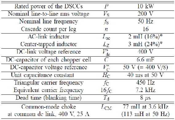
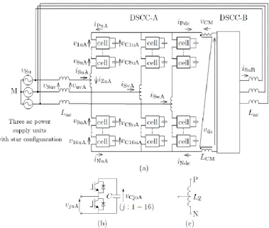
Figure 2(a) shows the circuit configuration for a transformerless DSCC-based BTB system used in experiments and simulations. Table 1 summarizes the circuit parameters of Fig. 2(a). Figure 2(a) is a simplified model of Fig. 1, in which the following reasonable assumptions are made:
[image:2.595.132.485.457.595.2] The impedances in feeder A and feeder B are neglected, while two ac-link inductors are used to connect the feeders and the BTB system;
The currents flowing to the loads or flowing out from the distributed power generators are set to zero.
Table 1. Circuit parameters of Fig. 2.
2.2. Circuit Equations
Figure 2(a) shows the power circuit configuration of the DSCC-based BTB system with a per-leg chopper-cell count of 16 producing 17-level (33-level in line-to-line) pulse width modulation (PWM) waveforms [16]. The chopper-cell uses a dc capacitor and two IGBTs that form a bidirectional chopper as shown in Fig. 2(b). Here, vju is the low-voltage side voltage of each chopper-cell. In Fig. 2(a), a couple of identical DSCCs,
“DSCC-A” and “DSCCB” are connected back-to-back without any common dc-link capacitor. Each DSCC consists of 48 chopper cells depicted in Fig. 2(b), and three-center-tapped inductor in Fig. 2(c). In Fig. 2(a), iPuA and iNuA are the positive and negative arm currents, iSuA is the supply current, and iZuA is the
circuit current along the u-phase leg of DSCC-A. Hence, the following equations exist among the four currents:
) (
2 1
NuA PuA
ZuA i i
i , (1)
) 2
( ZuA
SuA
PuA i
i
i , (2)
) 2
( ZuA
SuA
NuA i
i
[image:3.595.172.457.171.366.2]Fig. 2. Circuit configuration for the transformerless DSCC-based BTB system with a cascade of n = 16. (a) Main circuit. (b) Chopper cell. (c) Center-tapped inductor [15].
3.
Modelling and Zero-Sequence Components
A zero-sequence current i0 may flow when two load ends of feeder A and feeder B are connected by a
transformerless BTB system, in which i0 is defined as
( ) , , , , , , 0 NxA w v u x pxA w v u x w v u x i i
i
Ndc Pdc i i
i0 , (4)
where iPdcand iNdcare dc-link currents at positive bus and negative bus, respectively.
Figure 3 shows an equivalent circuit with a focus on zero-sequence components derived in [1]. Here, each arm is represented by a voltage source (e.g., vPuA or vNuA), which is the sum of low-voltage-side voltages
of the corresponding chopper cells. It should be noted that i0 circulates through feeder A and feeder B, and
no zero-sequence current flows in the common ac mains because the 6.6-kV utility distribution systems in Japan are based on a three-phase ungrounding system. In addition, the background system inductance Ls
does not affect io because no zero-sequence current flows in Ls. Figure 3(a) can be changed to Fig. 3(b), in
which three wires at the ac sides are summarized to a single wire. Each of six legs in Fig. 3(b) produces the same amount of zero-sequence voltage. Figure 3(b), therefore, is changed to Fig. 3(c), where v0 is a
zero-sequence voltage produced by each arm. The detail on how to derive Fig. 3(c) is given in [1].
Figure 4 shows the block diagrams of power control and zero-sequence current control used in DSCC-A. The power control is achieved by the conventional decoupled current control and the detail is given in [14]. The zero-sequence current i0 contains low-frequency components less than 1 Hz and switching-ripple
components around several kilo-hertz. Ideally, i0 contains no low-frequency components less than 1 Hz.
[image:4.595.110.490.76.397.2]common voltage reference which is determined by the feedback control of i0 and its reference i0∗ = 0 as
shown in Fig. 4. On the other hand, the switching-ripple components around several kilo-hertz should be suppressed by using the appropriately-designed common-mode choke LCM connected to the common dc
link [1].
(a)
(b)
(c)
[image:5.595.129.463.139.704.2]Fig. 4. Block diagrams of power control and zero-sequence current control used in DSCC-A [15].
4.
Simulation and Analysis Results
Figure 5 shows simulated waveforms of the zero-current components during normal voltage condition, where p* = 10 kW and qA*= qB* = 0 kVA. Figure 5(a) shows the zero-sequence voltage of DSCC-A, v0A and
that of DSCC-B, v0B. Here, v0A is not equal to v0B. The zero-voltage component v0 is 7.3 V in rms as shown
in Fig. 5(b), while the voltage across common-mode choke vCM is 10.2 V in rms as shown in Fig. 5(c).
Figure 5(d) shows the three waveforms of zero-sequence current i0 under different conditions such as: (1)
No control and No common-mode choke, (2) control and No common-mode choke, and (3) PI-control and common mode choke. As can be seen in Fig. 5(d), i0 consists of mainly dc component, low
frequency components and high-switching ripple components. The dc and low-frequency components can be suppressed by using the PI-controller in which the rms value of i0 is decreased from 1.86 A (No
PI-control) to 0.5 A (with PI-PI-control). However, the PI-control cannot suppress the high-frequency components. Hence, the combination of feedback control and connecting a common-mode choke to the common dc link is required to mitigate the zero-sequence current circulating consisting of low and high frequency components. The blue-line waveform in Fig. 5(d) shows that the zero-sequence current can be suppressed as small as 10 mA (0.03%) in rms, which is small enough to be negligible, compared to the rated feeder current 30 A ( /√ ). Note that in the actual system, the zero-sequence current should be controlled less than 200 mA (0.06%) of the rated capacity of the feeder 300 A to avoiding malfunction of grounding-detection relays [16].
5.
Conclusion
[image:6.595.127.489.78.373.2]0.01 A in rms at the rated dc-link current 25 A or 0.03% in rms of rated feeder current 30 A, which is within acceptable value and small enough to negligible.
Fig. 5. Simulation waveforms of the zero-sequence components during normal voltage condition, where
p* = 10 kW and qA*= qB* = 0 kVA: (a) Comparison between zero-sequence voltage of DSCC-A, v0A and
that of DSCC-B, v0B.; (b) Zero-sequence voltage v0 (= v0A); (c) Voltage across common-mode choke vCM; (d)
Fig. 6. Frequency spectra of zero-sequence current (i0) in Fig. 5.: (a) Low-frequency band; (b)
High-frequency band.
References
[1] P. Khamphakdi, K. Sekiguchi, M. Hagiwara, and H. Akagi, “A transformerless back-to-back (BTB) system using modular multilevel cascade converters for power distribution systems,” IEEE Trans. Power Electron., vol. 30, no. 4, pp. 1866–1875, Apr. 2015.
[2] B. Gemmell, J. Dorn, D. Retzmann, and D. Soerangr, “Prospects of multilevel VSC technologies for power transmission,” in Transmission and Distribution Conference and Exposition, 2008. T&D. IEEE/PES, 2008, pp. 1–16.
[3] H. Abu-Rub, M. Malinowski, and K. Al-Haddad, Power Electronics for Renewable Energy Systems, Transportation and Industrial Applications. John Wiley & Sons, 2014.
[4] M. Perez, S. Bernet, J. Rodriguez, S. Kouro, and R. Lizana, “Circuit topologies, modeling, control schemes, and applications of modular multilevel converters,” IEEE Trans. Power Electron., vol. 30, no. 1, pp. 4–17, 2015.
[5] A. Nami, J. Liang, F. Dijkhuizen, and G. Demetriades, “Modular multilevel converters for HVDC applications: Review on converter cells and functionalities,” IEEE Trans. Power Electron., vol. 30, no. 1, pp. 18–36, 2015.
[7] S. Rohner, S. Bernet, M. Hiller, and R. Sommer, “Modulation, losses, and semiconductor requirements of modular multilevel converters,” Industrial Electronics, IEEE Transactions on, vol. 57, no. 8, pp. 2633–2642, Aug. 2010.
[8] S. Debnath, J. Qin, B. Bahrani, M. Saeedifard, and P. Barbosa, “Operation, control, and applications of the modular multilevel converter: A review,” IEEE Trans. Power Electron., vol. 30, no. 1, pp. 37–53, Jan. 2015.
[9] J. Wang, R. Burgos, and D. Boroyevich, “A survey on the modular multilevel converters modeling, modulation and controls,” in Energy Conversion Congress and Exposition (ECCE), 2013 IEEE, 2013, pp. 3984–3991.
[10] M. Davies, M. Dommaschk, J. Dorn, J. Lang, D. Retzmann, and D. Soerangr, “HVDC PLUS basics and principle of operation,” Siemens Energy Sector, HVDC PLUS V3, Tech. Rep., 2008.
[11] C. Westerlind, V. Lescale, and B. Jacobson, “HVDC technology for large scale offshore wind connections,” presented at EWEA 2011, Brussels, Belgium: Europe’s Premier Wind Energy Event, 2011. [12] F. Hassan and C. Davidson, “HVDC-VSC: Transmission technology of the future,” Alstom Grid
Spring-Summer 2011 1, Tech. Rep., 2011.
[13] H. Akagi, “Classification, terminology, and application of the modularmultilevel cascade converter (MMCC),” IEEE Trans. Power Electron., vol. 26, no. 11, pp. 3119–3130, Nov. 2011.
[14] P. Khamphakdi, K. Sekiguchi, M. Hagiwara, and H. Akagi, “Zero-voltage ride-through capability of a transformerless back-to-back system using modular multilevel cascade converters for power distribution systems,” IEEE Trans. Power Electron., vol. 31, no. 4, pp. 2730–2714, Apr. 2016.
[15] K. Sekiguchi, P. Khamphakdi, M. Hagiwara, and H. Akagi, “A grid-level high-power BTB (back-to-back) system using modular multilevel cascade converters without common DC-link capacitor,” IEEE Trans. Ind. Appl., vol. 50, no. 4, pp. 2648–2659, Jul/Aug. 2014.
![Fig. 1. A 6.6-kV power distribution system consisting of two radial feeders equipped with a DSCC-based BTB system [1]](https://thumb-us.123doks.com/thumbv2/123dok_us/8107709.235533/2.595.132.485.457.595/power-distribution-consisting-radial-feeders-equipped-dscc-based.webp)
![Fig. 3. Equivalent circuits for zero-sequence components [1].](https://thumb-us.123doks.com/thumbv2/123dok_us/8107709.235533/5.595.129.463.139.704/fig-equivalent-circuits-zero-sequence-components.webp)
![Fig. 4. Block diagrams of power control and zero-sequence current control used in DSCC-A [15]](https://thumb-us.123doks.com/thumbv2/123dok_us/8107709.235533/6.595.127.489.78.373/block-diagrams-power-control-sequence-current-control-dscc.webp)
