N
N
N
N
UCLEAR
UCLEAR
UCLEAR
UCLEAR
F
F
F
F
UELS
UELS
UELS
UELS
present and future
Donald R. Olander
University of California, Berkeley
Corresponding author: Fax: 01 510 526 0556;
email: [email protected]
ABSTRACT
The important new developments in nuclear fuels and their problems are
reviewed and compared with the status of present light-water reactor fuels.
The limitations of these fuels and the reactors they power are reviewed with
respect to important recent concerns, namely provision of outlet coolant
temperatures high enough for use in H
2production, destruction of plutonium to
eliminate proliferation concerns, and burning of the minor actinides to reduce
the waste repository heat load and long-term radiation hazard. In addition to
current oxide-based fuel-rod designs, the hydride fuel with liquid metal thermal
bonding of the fuel-cladding gap is covered. Finally, two of the most promising
Generation IV reactor concepts, the Very High Temperature Reactor and the
Sodium Fast Reactor, and the accompanying reprocessing technologies,
aqueous-based UREX and pyrometallurgical, are summarized. In all of the
topics covered, the thermodynamics involved in the material’s behavior under
irradiation and in the reprocessing schemes are emphasized.
KEYWORDS
I . Introduction
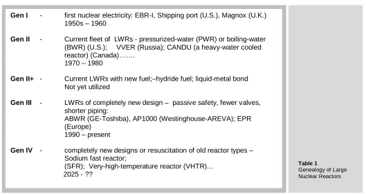
The history and future of the nuclear reactor designed for electricity production (and other uses) are shown in Table 1. In the U.S., the light-water reactors (LWRs) now in operation were designed and for the most part built in the decade of the seventies. This phase of nuclear-reactor orders came to an abrupt halt with the advent of the Three Mile Island reactor accident. In the U.S. there has been a 30-year lacuna in design and construction of any type of nuclear reactor.
The rapid rise in the cost of natural gas have made power plants using this fuel less desirable than it has been in the past. Coal-fired plants suffer from the carbon dioxide that they emit. Consequently, there has been a “renaissance” of sorts of nuclear power, resulting in the U. S., of well over 30 applications for construction-and-operating licenses for Gen III reactors have been submitted to the Nuclear Regulatory Commission. However, no money has yet been invested for their construction .
The pressure of competing economically with electricity produced by burning coal and natural gas has driven current reactor operators to seek ever higher burn-up of their fuel. The current fuel design has reached its limit at a burn-up estimated to be ~ 80 MWd/kgU. In addition, light-water reactors produce outlet coolant water at a maximum temperature of ~ 320oC, which limits the efficiency of converting heat to electricity to ~ 33% and precludes use as process heat for H2 production.
Moreover, concerns that were not present when the current fleet of reactors was designed have arisen. The two most important are the need to burn the minor actinides (MA), also called transuranics (TRU)1, and the need to reprocess fuel in a manner that never exposes pure plutonium. The reason for the former is to reduce the radioactivity and heat generation rate of nuclear wastes at long storage times. Because of their long half-lives, the minor actinides remain after essentially all of the fission products have decayed. Containing plutonium in a mixture whose radioactivity is high enough to deter separation into weapons purity is referred to as proliferation resistance. These two needs are met by changing both the design of the reactor and its fuel and by the method of treating the spent fuel.
In this paper, the materials constraints of the current light-water reactors are described along with a new fuel that eases the burn-up limitation. Finally, two of the so-called Generation IV reactor concepts and their associated reprocessing methods are reviewed.
1
The minor actinides include Np, Am and Cm
Gen I - first nuclear electricity: EBR-I, Shipping port (U.S.), Magnox (U.K.)
1950s – 1960
Gen II - Current fleet of LWRs - pressurized-water (PWR) or boiling-water
(BWR) (U.S.); VVER (Russia); CANDU (a heavy-water cooled reactor) (Canada)…….
1970 – 1980
Gen II+ - Current LWRs with new fuel;–hydride fuel; liquid-metal bond
Not yet utilized
Gen III - LWRs of completely new design – passive safety, fewer valves,
shorter piping:
ABWR (GE-Toshiba), AP1000 (Westinghouse-AREVA); EPR (Europe)
1990 – present
Gen IV - completely new designs or resuscitation of old reactor types –
Sodium fast reactor;
[image:2.595.37.566.467.748.2](SFR); Very-high-temperature reactor (VHTR)… 2025 - ??
Table 1
Il. Gen II Fuel assemblies and fuel elements for
light-water reactors
A LWR reactor core is comprised of fuel assemblies in an arrangement that satisfies the following requirements:
i) to provide a rigid structure for holding the fuel elements ii) to deliver the desired thermal power to the coolant
iii) to provide a critical assembly with a minimum of neutron leakage
iv) to provide adequate coolant flow to remove fission heat and sufficient coolant volume for thermalization of fission neutrons by hydrogen.
v) to accommodate control rods that maintain criticality as the fuel is consumed
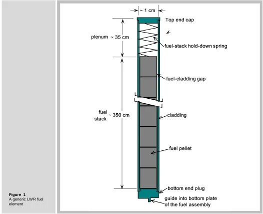
Figure 1 shows a generic LWR fuel element. It consists of a ~ 4 m length of a zirconium-alloy tube with an OD of ~1.2 cm for boiling-water reactor (BWR) fuel rods and 0.8 cm OD for PWR rods. This cladding tube is filled with a ~3 m stack of fuel pellets, either UO2 with
uranium enrichments up to 5% or a mixture of UO2 and PuO2 (MOX). The remaining space
above the fuel stack is an open volume called a plenum, which is designed to accommodate normal fission gas release from the fuel without over pressurizing the cladding.
Figure 1
[image:3.595.32.558.298.725.2]2.1 Fretting failure of the cladding
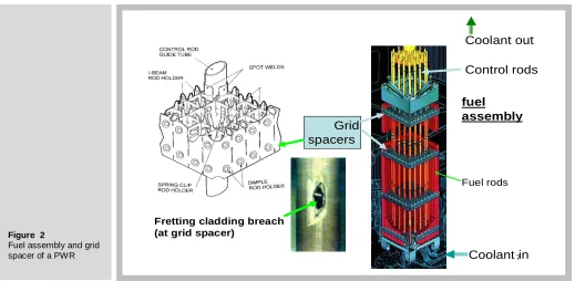
Figure 2 shows a cutaway drawing of the fuel assembly of a pressurized water reactor (PWR) and a very important component, the grid spacer through which the fuel rods pass. The cladding tubes are fixed in the grid spacer by rod holders, of which three types are shown. The design of rod holders is a true engineering compromise. If held too tightly, vertical thermal expansion of the rods due to temperature changes is impeded; if the rods are not firmly gripped, flow-induced vibration of the rods within the grid occurs. In either case, a fretting breach of the cladding as shown in the figure can result. This is the principal cause of cladding failure of LWR fuel rods.
2.2 Coolant chemistry
PWR coolant contains:
- boric acid enriched in B10 for nuclear reactivity control, - lithium hydroxide to minimize corrosion by adjusting the pH,
- zinc (added as an organometallic compound) to reduce the transfer of radioactivity from the fuel rods to walls of the coolant circuit
- hydrogen to remove highly-oxidizing species created by radiolysis of water.
Solid solutes cannot be added to BWR coolant water because vaporization at the upper portion of the fuel assembly would result in accumulation of the solutes in the liquid. Only hydrogen treatment is accorded to BWR coolant.
2.3 Cladding corrosion
Despite the above adjustment of the water chemistry, severe corrosion occasionally occurs, as shown in Fig. 3. The left hand photograph shows the type of corrosion observed on BWR cladding. The white spots are ZrO2 which was formed by ingress of
water through cracks in the otherwise intact oxide film. This is termed nodular corrosion.
Because the cladding OD temperatures are higher in a PWR (by about 20oC), uniform corrosion is more extensive than on BWR cladding. In addition, a mixture of iron and chromium spinel called CRUD collects on the cladding from deposition of Fe, Ni and Cr ions that have entered the coolant by corrosion to stainless steel piping in the primary coolant loop. This layer, which is not a corrosion layer, is harmful for two reasons. First, it can occlude boron from solution and alter the axial neutron flux distribution. Second, it can release radioactive transition-metal nuclides that plate out at downstream locations in the primary circuit. The uniform corrosion layer beneath the CRUD is limited to a thickness of 100 microns. More extensive corrosion reduces the tube cross section sufficiently to increase the stresses in this component.
2.4 Hydrogen embrittlement
The second consequence of corrosion, particularly in PWRs, is absorption of ~ 15% of the corrosion-product hydrogen in the substrate metal, as shown in the lower photograph of Figure. 3. The terminal solubility of hydrogen in zirconium is sufficiently low that platelets of zirconium hydride precipitate out. These precipitates result in significant loss of ductility of the metal.
2.5 Pellet-Cladding Interaction
As a result of conversion by fission of one atom of uranium to two fission-product atoms, the fuel swells during irradiation. In addition, the steep temperature gradient in the fuel pellet generates thermal stresses that exceed the fracture stress of UO2. The
First, embrittlement due to hydrogen precipitates permits the stress to initiate cracking on the cladding OD. Second, the chemical effect of fission products such as iodine and cadmium on incipient cracks in the cladding ID can result in stress-corrosion cracking. This phenomena is termed pellet-cladding interaction (PCI), and remains a non-negligible source of cladding failures during operation.
Figure 5 shows a typical stress-corrosion crack in the cladding. In addition to the uniform stresses engendered by pellet expansion, localized stresses are built up in regions where a piece of the pellet is missing, usually due to chipping during fabrication. This missing pellet fragment, when it occurs next to a crack in the fuel, is an especially potent source of PCI. The crack in the fuel facilitates movement of the dangerous fission products from the hot center of the pellet where release occurs to the fuel-cladding interface and from there to the tip of the crack in the cladding. Here the ductile metal is converted to the metal iodide ZrI4, which is brittle and facilitates
progression of the crack.
2.6 Fission-gas release
Two deleterious phenomena result from release of the fission gases Kr and Xe from the fuel. The first concerns the portion that accumulates in the fuel-cladding gap, where the heavier rare gases replace some of the original helium. The consequence is a greatly reduced thermal conductivity of the gas. If the gap has not been closed by fuel swelling, this admixing causes the fuel temperature to rise, which in turn results in increased release of fission gas. This “bootstrapping” effect can result in excessively high fuel temperatures and larger-than-usual fission-gas release fractions.
The second life-limiting feature arises from the fission gases that accumulate in the plenum (Figure 1). If the added gas causes the pressure here to exceed the coolant pressure, the cladding “lifts off” the fuel, thereby increasing the gap size and its thermal resistance.
2.7 Life-limiting phenomena
[image:5.595.41.560.550.804.2]Any one these phenomena, namely fretting wear, cladding corrosion, hydrogen embrittlement, pellet-cladding interaction or excessive internal pressure due to fission-gas release, can be life-limiting for LWR fuel elements. The maximum burn-up of current fuel designs is ~ 60 MWd/kgU. At greater burn-ups, the probability of a cladding failure becomes significantly larger than the current value of ~10-5. Rupture of the cladding of a single fuel element in the core is more of an economic concern than a safety issue. Release of fission products and fuel through the breach in the cladding spreads radioactivity throughout the primary coolant circuit, necessitating reactor shutdown, replacement of the fuel assembly containing the defective fuel rod and extensive decontamination of exposed components.
Figure 2
Fuel assembly and grid
spacer of a PWR 7
Control rods
Grid spacers
Fuel rods
Coolant in Coolant out
Fretting cladding breach (at grid spacer)
12
Beginning of life
Pellets swelling
Gaseous fission products (Xenon, Krypton...)
Density and porosity evolve with burn
Density and porosity evolve with burn--upup
After 1 cycle
“Bambooing”
Thermal stress cracks
Swelling due
to solid fission
products
Gap closure - PCI
Stress concentration
“hourglassing”
Figure 3
Corrosion of Zirconium-alloy LW R cladding
Figure 4
Effects of fuel swelling and thermal stresses
Fuel
cladding
Thermal-stress crack (fission-product path)
Chip off pellet
Stress-corrosion crack
Gap closes due to
fuel swelling
Figure 5
Consequences of pellet-cladding interaction (PCI)
PWR CRUD
Hydride
UO2pellet
cladding Oxide scale
III. Gen II+ Advanced Fuels for LWRs
3.1 Mixed U-Pu oxide (MOX)
Until now, the only fuel other than UO2 that has been burned in LWRs is the mixed
oxide (U,Pu)O2. This fuel does not require isotope enrichment and serves as a means
of disposing of plutonium from weapons programs and recycled Pu from reprocessing of spent LWR fuel. Its irradiation performance is no better than that of UO2, and may
even be less desirable.
Depending on the method of fabricating MOX fuel, the microstructure may a three-phase system with dispersed PuO2 and UO2 particles embedded in a mixed-oxide
matrix [1] or a two-phase material with (U,Pu)O2 particles in a continuous UO2 phase
[2] . Figure 6 shows electron microprobe pictures of the MOX microstructures of the latter type. The large white spots are the Pu-rich particles where the bulk of the fissions occur.
In some but not all reports, fission-gas release from MOX is higher than that from UO2,
mainly because its thermal conductivity is ~10% lower, thereby increasing fuel temperature. Figure 7 shows the scanning electron microscope and optical microscope images of high-burnup regions of the two-phase type of MOX described above. The SEM image reveals large bubbles of fission gas in a plutonium-rich agglomerate close to the cladding inner surface. Optical image (b) shows precipitates of noble-metal fission products in the same region. Fuel-cladding contact is so intimate that a mixed (U,Zr)O2 layer has developed on the inner Zircaloy surface.
In addition, the ratio of the fissile isotopes 239Pu + 241Pu to the non-fissile isotopes
240
Pu + 242Pu decreases with each recycle. This requires increasing total Pu loadings to maintain criticality. [3]. A maximum Pu/U+Pu ratio of 0.1 is permitted in order to avoid a positive void coefficient. On the favorable side, the creep rate of MOX is greater than that of UO2, which results in reduction of the bambooing effect shown in
Fig. 4 and the consequent risk of cladding failure by excessive hoop stress on the cladding.
3.2 Hydride fuel with a liquid-metal bond
This fuel combines features from two very different reactors into a promising new fuel for LWRs. Instead of UO2 or MOX, the fuel is the hydride of uranium and zirconium,
(U0.31Zr)H1.6 [4]. This fuel consists of particles of metallic uranium dispersed in a matrix
of ZrH1.6 (Fig. 8). It powers the well-known TRIGA research reactors [5].
The advantages of the hydride over the oxide fuel include:
- A part of the moderator (H) is in the fuel; not all moderation need be provided by the hydrogen in the coolant. This is especially important in BWRs, where the upper reaches of the core are filled with steam, which has very little capacity for moderating neutrons. Even in a PWR, the coolant channel cross section can be reduced because the water is needed only for cooling, not for moderation of neutrons. In both cases, the fuel rods can be more closely packed, which reduces the volume of both the core and the pressure vessel.
- Higher burn-up can be attained in a hydride-fueled LWR than in one with oxide fuel [6 ]
- The negative reactivity feedback in a transient is faster with hydride fuel than with oxide fuel (TRIGA reactors are routinely pulsed by rapid control-rod withdrawal) - The thermal conductivity of the hydride is ~ 6 times greater than that of UO2, and
is much less temperature-dependent [5]. Consequently, for a linear power of 375 W/cm, for example, the maximum fuel temperature is < 700oC. For an oxide fueled rod operating at the same linear power, the maximum temperature would be close to 2100oC. The result is a significant reduction is stored energy and fission-product release.
initial gap thickness of ~ 80 µm. With this size, the gap closes after about one year of irradiation, and thereafter fission-product swelling continues to strain the cladding.
A second problem with helium bonding of the fuel-cladding gap is that pre-pressurization of the rod during fabrication of ~ 20 atm is required. The reason is that with a lower He concentration, mixing with released fission gas (mainly Xe) would degrade the thermal conductivity of the gas to an unacceptable level.
In order to maintain a sufficiently low fuel temperature in a hydride-fueled rod, helium cannot be used as a thermal bond in the fuel-cladding gap. Instead, a low-melting (~ 120oC) metal alloy consisting of equal parts by weight of lead, tin and bismuth is the gap filler. As a liquid, this material has a thermal conductivity that is 100 times greater than that of helium, which essentially eliminates the gap thermal resistance. The alloy does not react with water and has a very low neutron cross section. Several important advantages flow from the use of a liquid metal (LM) in the gap.
- At a linear heat rate of 375 W/cm, the maximum fuel temperature is reduced to ~ 550oC from ~ 700oC with a helium bond [4], resulting in practically no thermal release of fission gases.
- The liquid metal protects the cladding ID from noxious fission products, which, as shown in Fig. 5, helium cannot.
- The initial gap thickness can be made wide enough to prevent contact of fuel and cladding for the entire lifetime of the fuel element [7]. This means that the cladding is never stressed in tension, so cracking of the type shown in Fig. 5 is avoided. - In the event of a cladding breach, such as the fretting hole shown in Fig. 1, the LM
in the gap is blown into the plenum by the inrush of coolant, which flashes to steam. However, the LM beneath the breach is unaffected, and prevents ingress of steam to the bottom of the rod. This serves to prevent secondary hydriding, the cause of some spectacular cladding failures in conventional He-bonded fuel rods.
The LM-bonded hydride fuel rod is intended to replace oxide fuel in existing LWRs with no change in cladding dimensions. However, in the construction of the Gen III LWRs, the fuel-rod pitch can be reduced, resulting in a smaller core and pressure vessel.
There are, however, several significant disadvantages of LM-bonded hydride fuel rods. First, the uranium density of the hydride is only 40% that of oxide fuel. To maintain the same linear power, the U-235 enrichment must be increased by a factor of 2.5 – that is, to 10 – 12%. This not only incurs a nontrivial increase in the enrichment component of the fuel-fabrication cost, but requires a major revision of the regulations governing maximum enrichment for power reactors (5%).
Figure 6
Electron microprobe images MOX fabricated by two methods [1]
Figure 7
SEM (a) and optical microscope (b) images of a former Pu-rich agglomerate in high-burnup MOX [2]
Black: U
Gray: ZrH
1.6
10
µ
µµ
µ
m
Figure 8
Optical microscope picture of hydride fuel
21
LM fills pellet-pellet interface
LM fills gap
and cracks
in fuel
IV. Gen IV New (or recussitated) reactor designs
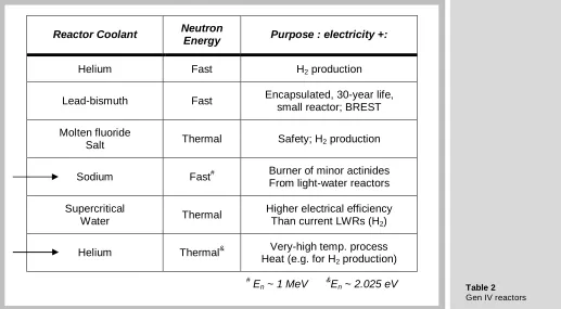
Several years ago, the U. S. DOE and international collaborators selected for detailed study six advanced reactor systems and their accompanying reprocessing schemes. The reactor concepts are shown in table 2. Three are fast-neutron reactors, in which moderating material is absent and three are thermal-neutron reactors, which rely on moderators such as hydrogen or carbon to reduce the 1 MeV fission neutrons to ~ 0.03 eV thermal neutrons. Of the six, only the two that are most likely to be constructed are reviewed here.
Reactor Coolant Neutron
Energy Purpose : electricity +:
Helium Fast H2 production
Lead-bismuth Fast Encapsulated, 30-year life, small reactor; BREST
Molten fluoride
Salt Thermal Safety; H2 production
Sodium Fast# Burner of minor actinides From light-water reactors
Supercritical
Water Thermal
Higher electrical efficiency Than current LWRs (H2)
Helium Thermal& Very-high temp. process Heat (e.g. for H2 production)
#
En ~ 1 MeV &
[image:10.595.39.563.51.321.2]En ~ 2.025 eV
Figure 9
Destructive examination of an as-fabricated LM-bonded fuel rod
Table 2
[image:10.595.39.556.461.746.2]V. Very-high-temperature reactor (VHTR)
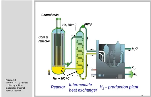
Figure 10 is a flow diagram of the VHTR listed in the last row in Table 2. A number of reactors of this type have been built and operated (e.g., the Fort Saint Vrain reactor in Colorado), but none are currently operating. The VHTR is explicitly designed to produce outlet coolant temperatures high enough to operate a hydrogen production plant. It may also generate electricity as a byproduct. It is a loop-type reactor, meaning that the coolant flows through the core and delivers energy to an external heat exchanger. In this sense, the VHTR is similar to LWRs. The helium coolant transfers energy to an intermediate heat exchanger, which may utilize either steam or helium as a secondary coolant stream. The primary helium from the reactor is not sent directly to the hydrogen plant in case the coolant is contaminated with fission products from leaking fuel.
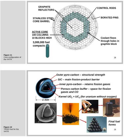
Figure 11 is a cross section of the core of the VHTR. The shaded hexagons represent graphite blocks with axial holes, some for coolant flow and the rest for holding the small compacts containing fuel. The open hexagons in the drawing are graphite blocks without any penetrations. Their function is to reflect neutrons that leak from the core back to the core.
The heart of the VHTR are the small particles of fuel shown on the left of Fig. 12. These 1 mm-diameter spheres contain a fuel kernel surrounded by three CVD layers of carbon and one layer of silicon carbide. Each layer has a distinct function, as indicated on the figure. The spheres are called tri-isotropic (TRISO)-layered particles; they were developed in Germany.
The two types of graphite forms in which the fuel particles are dispersed are shown in the lower right of Fig. 12. One option is to embed the particles in a 5-cm long, 1.2-cm diameter graphite cylinder called a compact. These are then inserted into holes in the hexagonal graphite blocks that form the reactor core shown in Figure. 11. The other fuel form in which TRISO particles are contained are graphite spheres the size of tennis balls called pebbles. To form a reactor, these are loaded into a core barrel of the appropriate dimensions to yield a critical mass. This so-called pebble-bed reactor, acronym THTR, was first constructed in Germany and operated from 1986 through 1989. A nearly identical reactor is currently under construction in South Africa. The VHTR in the U. S. Gen IV program will be of the graphite-block type shown in Fig. 11.
24
Control rods
Core &
reflector
He, ~ 900
oC
He, 500
oC
Intermediate
heat exchanger
H
2– production plant
Reactor
pump
H
2O
O
2 [image:11.595.28.554.452.790.2]H
2Figure 10
5.1 Fuel-particle Chemistry
Fission of uranium produces an array of products that bind varying amounts of the oxygen released when a uranium atom fissions. This chemical effect profoundly influences the thermochemistry the particle and ultimately its integrity.
The temperature and the O/U of the fuel dictate the oxygen partial pressure, or the oxygen potential:
RTlnpO2 = F(O/U,T). (1)
For UO2±x the function F(O/U,T) is given, for example, in Ref. [9]. The oxygen
potential determines: i) the oxidation states of the fission products; and ii) the pressure of carbon monoxide in the buffer. Consequently, determination of the effect of burn-up on the O/U of the fuel is the key problem to be worked out.
Some kernel designs utilize the mixed oxide (U,Pu)O2-x, in which case the function F
contains the U/Pu ratio as a variable. Considerable effort has gone into thermodynamic modeling of the U-Pu-O ternary system [10, 11].
5.2 The oxidizing effect of fission in UO
2Fission causes uranium to disappear but does not affect oxygen. The latter can either be bound to reactive fission products or remain in the fuel associated with uranium. The oxygen-to-uranium ratio changes during fission according to:
O 2 S FIMA
U 1 FIMA
− × =
− (2)
where FIMA is a measure of burn-up that stands for the Fraction of Initial Metal Atoms that have fissioned. S is the sum over all fission products of the atoms of oxygen bound to each:
S=
∑
y Ai i (3)where yi is the yield of fission product i and Ai is the number of oxygen atoms it binds.
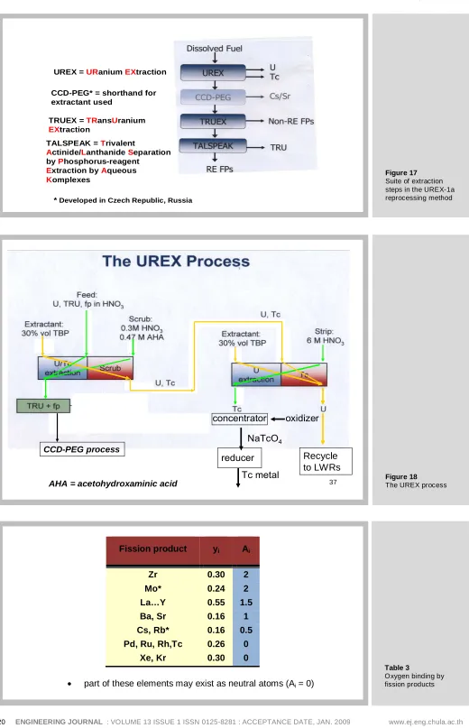
These are shown in Table 3. Whether the O/U ratio decreases with burn-up depends on S. If this sum is less than 2, the O/U ratio increases with burn-up, or the fuel becomes hyperstoichiometric. If S > 2, the fuel turns hypostochiometric.
Forming this sum from the entries in Table 3 gives S = 2.15. According to Eq (2), this should result in decreasing O/U with burnup. However, as noted in the table, Mo and the Cs,Rb combination may exist partially in the elemental state, and not bind oxygen. If Ai for these fission products is zero, S = 1.59, and the fuel becomes progressively
hyperstoichiometric with burn-up. Where in the range 1.59 < S< 2.15 the actual value lies depends on the details of the thermochemistry, particularly of Mo. In most cases, the sum is less than 2 because enough Mo exists as the element combined with the noble metals rather than as Mo4+ in the fuel where it binds oxygen [12].
In a typical LWR fuel element, the inner cladding surface scavenges excess oxygen by forming ZrO2. In the fuel kernel of a TRISO particle, on the other hand, the only
oxygen sink is the pure carbon of the buffer layer. Unfortunately, when this oxidizes, the gas produced (CO) contributes to the internal pressure in the particle. In addition, a portion of the oxygen not bound to fission products remains in the fuel, thereby converting UO2 to UO2+x.
5.3 A practical TRISO particle
A workable fuel for a VHTR differs from the fully-enclosed UO2 kernel described above
in two ways, both related to the buffer layer of carbon surrounding the kernel: i) A restricted void space is available to accommodate gases; ii) the kernel is in contact with carbon.
As UO2+x is formed during burnup, it is reduced to UO2 by the reaction:
where a = x’ – x << 1. The carbon monoxide produced by this reaction accumulates in the porosity of the buffer layer The CO pressure in this volume can attain large values if the fuel is pure UO2 and, along with the pressure contributed by the released fission
gases, can compromise the integrity of the pyrocarbon layers (Figure. 13a).
Equation (4) is not an equilibrium reaction; it is meant solely to indicate the role of carbon in maintaining the stoichiometry of the fuel but at the expense of producing CO.
The sequence of steps in modeling the thermochemistry of an initially-stoichiometric UO2 kernel is sketched in Fig. 14. N initial moles of UO2 with burn-up given by FIMA
results in reduction of the quantity of uranium but does not affect the oxygen. Because S < 2, oxygen is “liberated” from the fuel as burn-up proceeds. Instead of remaining in the fuel, the excess O is partitioned between the fuel and the gas phase. The partitioning is described by f, which is defined as the fraction of the available oxygen that remains with the fuel (in excess of that combined with reactive fission products). The fraction 1-f, which is termed “free” oxygen in Fig. 14, escapes to the gas phase in the buffer void volume. Because the equilibrium constant of the reaction
2C + O2 = 2CO,
2
2 CO O
K
=
p
/ p
(5)is very large, essentially all of the gas-phase oxygen is present as CO.
The fraction f is determined as follows. The CO partial pressure shown in the right-hand box in the middle of Figure. 14 is inserted into Eq (5) to determine
2
O
p
(as afunction of f). This result, along with the O/U ratio from the left-hand middle box in Figure. 14, is inserted into Eq (1) and the result solved (numerically) for f. With f determined, O/U and
p
CO are calculated. Finally, the partial pressure of O2 in thebuffer void space is given by Eq (5).
Another method of expressing the result of the thermochemical analysis is by the ratio of “free” oxygen to the number of fissions [13]:
free
fiss
O (1 f ) (2 FIMA S)
N FIMA
− × − ×
= (6)
Example S = 1.7 T = 1400 K FIMA = 0.5 Ofree/Nfiss = 0.14 [13 ]
For these values, Eq (6) gives f = 0.94. The following are typical values for the TRISO particle:
kernel diameter = 350 µm; kernel density = 10.4 g/cm3 → N = 6.5x10⁻⁷ moles UO2
buffer thickness = 100 µm; buffer porosity = 0.5 → Vbuffer = 3.2x10 -5
cm3
Using these numbers in the equations in the middle of Fig. 14 gives
p
CO= 154 atm and O/U = 2.17.5.4 Influence of UC
2In the U. S. VHTR, the fuel is a 3:1 ratio of UO2:UC2. The role of the UC2 is
straightforward: as UO2+x is converted to UO2+x’ with burn-up, UC2 reduces it back to
UO2+x according to 2
:
UO2+x’ + aUC2→ (1 + a)UO2+x +2aC (7)
where a = (x’ – x)/(2 + x) << 1. Because this sequence does not release CO, it is more desirable than the reaction that would occur in the absence of UC2 (Eq (4)).
2
To thermodynamically assess the effect of the UC2 component of the fuel, the
following equilibria need to be added to the analysis in Sect. 5.3:
UO2+x + (4+x)C = UC2 +(2+x)CO (8)
or
2UO2+x + (7+2x)C = U2C3 + 2(2+x)CO (9)
Whether the dicarbide or the sesquicarbide is present depends upon temperature. Above 1900 K, the former is stable [14].
The calculation proceeds as follows:
- Eq (5) provides a relation between
p
CO and2
O
p
- Eq (1) provides a relation between
2
O
p
and O/U = 2 + x- The equilibrium constant of Reaction (8) or (9) provides a relation between x and
p
CO3.
Three equations need to be solved simultaneously for the three unknowns. Because the CO pressure is very low, the fraction f of the liberated oxygen that remains in the fuel is unity, so the detailed calculation outlined in Figure. 14 is not needed.
The CO pressure from reactions (8) or (9) is very low; for reaction (8) at x = 0 and 1400 K, pCO = 2x10
-5
atm [13]. As long as UC2 is present, the CO pressure is very
small and the only stress on the inner pyrocarbon layer is due to released fission gases.
Since the initial ratio UC2/UO2 = γ is < 1, all of the UC2 will be consumed before all
U-235 is exhausted. A conservative estimate of the burn-up at which this occurs, denoted by FIMA*, can be obtained by assuming that O/U remains at 2 throughout irradiation. The equation in the fifth row of boxes in Fig. 14 yields the fraction f:
1 2
1 FIMA f
1 S FIMA
− =
− × (10)
and the “free” O equation in the fourth row of Fig. 14 gives Ofree = (2–S×FIMA) × NUO2,
where NUO2 is the initial number of moles of UO2 in the kernel (the N in Figure. 14).
According to Eq (8) with x = 0, two moles of CO are required to remove 1 mole of UC2,
so the moles of UC2 removed is (1 – ½ S) × FIMA × NUO2. In addition, fission removes
FIMA×NUC2 moles of uranium from the carbide, where NUC2 is the initial number of
moles of UC2 in the kernel. When the sum of these chemical and nuclear reductions in
UC2 equals the initial amount, all UC2 has disappeared. Thus, FIMA* is:
1 2
FIMA*
1
S
γ
=
−
+ γ
(11)For S = 1.7 and γ = 1/3, Eq (11) gives FIMA* = 0.23. At this burn-up, the buffering action of Eq (7) vanishes and the CO pressure jumps to the all-UO2 value of hundreds
of atm. Had the increase in the O/U ratio been taken into account, FIMA* would have been larger than 0.23. However, the full equilibrium calculation described at the beginning of this section would have to be performed. Also, Homan et al [15] have analyzed the additional consumption of UC2 by conversion of fission-product oxides to
the corresponding carbides. However, this was simply a mass-balance calculation and did not involve thermodynamics.
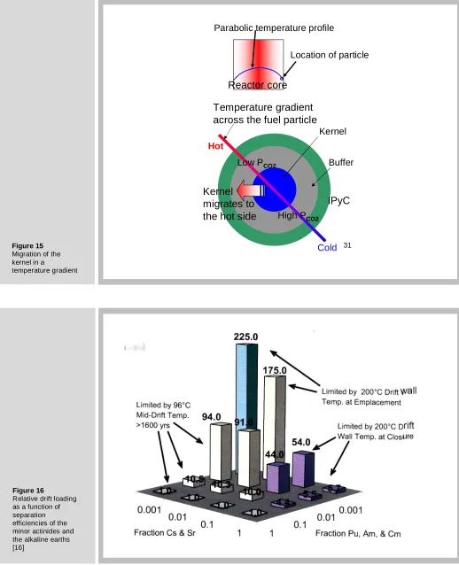
5.5 Kernel Migration
Mechanical rupture of the structural pyrocarbon layers of the particle (see Figure. 12) is not the only deleterious effect of CO on TRISO particle performance. Another is kernel “migration”, a phenomenon that appears to cause the kernel initially at the center of the particle to move off center. This is shown in Figure. 13b. If the kernel
3
“moves” as far off-center as to touch the SiC layer in Figure. 12, rupture of the latter can occur with concomitant loss of fission products.
Actually, the kernel does not move; the rest of the particle does. Figure 15 illustrates the mechanism. There is a temperature gradient through the compacts due to the necessity of transferring heat from the center to the edge, whence it ultimately reaches a coolant channel. As a corollary, each particle sustains a temperature gradient, and it is this non-uniformity that causes material movement.
The cause is the temperature dependence of the equilibrium constant for the reaction:
2CO = CO2 + C (12)
for which:
2
2
CO CO
K
=
p
/ p
(13)Being an exothermic reaction, K decreases with increasing temperature.
Consequently, the hot side of the particle has a lower CO2/CO ratio than the cold side.
This causes a flux of CO2 from the hot to the cold side. Upon arriving at the hot side,
CO2 reacts with C to maintain the equilibrium partial pressures. At the cold side, the
CO moving from hot-to-cold decomposes and deposits carbon. The net result is removal of carbon on the hot side and deposition of carbon at the cold side. This transfer of carbon gives the visual impression of kernel migration. Carbon is first removed from the buffer layer at the hot side, then from the inner pyrocarbon layer. The kernel eventually touches the silicon carbide layer.
Both the mechanical stress and the kernel migration effects are due to a high CO pressure in the buffer volume.
5.6 Reprocessing of particle fuel
5.6.1 The Purex process
At present, the only large-scale scheme for reprocessing spent nuclear fuel to separate fission products, plutonium, and uranium is the PUREX (short for plutonium extraction) process. This is an aqueous solvent-extraction method that was used to remove weapons-grade Pu from the uranium slugs irradiated in the Hanford production reactors. This process is also used in the UK and France (and soon in Japan); the separated plutonium is mixed with depleted uranium to form MOX fuel for LWRs.
Briefly, the PUREX process involves the following steps:
1. Dissolving the uranium in nitric acid. This leaves U as U6+ and Pu as Pu4+
2. Extracting U6+ and Pu4+ nitrates from the aqueous phase by contacting with a solvent containing the complexing molecule tributyl phosphate (TBP) in a diluent such as kerosene. The fission products and the minor actinides are not extracted because they are not complexed by TBP. 3 Scrubbing (stripping) the U and Pu from the organic phase to an
aqueous nitric acid phase.
4. Reducing Pu4+ to inextractable Pu3+ by passing the solution over a bed of iron filings.
5. Using the aqueous solution of U6+ and Pu3+ as the feed to a second solvent extraction to recover highly-purified U and Pu streams.
5.6.2 Recent changes in reprocessing requirements
The following new requirements for reprocessing have rendered the PUREX process obsolete:
1. For proliferation reasons, Pu can no longer be recovered in a pure state.
3. Burning and/or separation of the minor actinides and separation of the alkaline-earth fission products barium and strontium permit a denser loading of waste in a repository than is possible with un-reprocessed spent fuel. The reasons for this are temperature limitations at various times and positions in the repository. Figure 16 shows the relative waste-packing density compared un-reprocessed spent fuel [13]. The limiting temperatures are 200oC at the drift wall and 96o C half way between drifts4. The variables are the fraction of the minor actinides and Cs/Sr remaining in the waste following reprocessing. It can be seen that if all but 0.1% of these groups are removed, the drifts can be loaded with 225 times as much waste as un-reprocessed spent fuel elements. The heights of the columns are fixed by reaching limiting temperatures at various times. The limits are:
1. Drift wall at time of placement of the waste in the drift (25 yrs) 2. Drift wall at time of closure of the drift (100 yrs)
3. Mid-drift temperature for t > 1600 yrs.
Figure 16 shows that removal of the TRU nuclides is important in limit No. 3 while the short-term limits 1 and 2 are controlled by removal of Cs and Sr. This graph demonstrates the necessity of removing these two groups of elements from the spent fuel if the repository such as Yucca Mountain is to be capable of storing high-level waste for many years. If the prohibition on reprocessing in the U. S. continues and all of the waste currently stored on reactor sites were transferred as spent fuel to Yucca Mountain when it opens, the repository would be filled to capacity and have to shut down immediately.
5.6.3 The UREX1a Suite of Extractions
Figure 17 shows a much more complicated “suite” of extraction processes designed to remove the shortcomings of the old PUREX process. The first step, called UREX (for URANIUM EXTRACTION), separates uranium and technetium together from the spent fuel. A subsequent step (not shown) separates U and Tc from each other. The uranium is re-enriched with U-235 or Pu-239 and recycled to LWRs. The recovered Tc is alloyed with the Zircaloy cladding material and removed as waste.
The second step is called CCD-PEG after the extractant used removes cesium and strontium from the aqueous stream issuing from the UREX process.
The third process, TRUEX, removes all but the 3+ valence ions from the waste. The former are the rare earths and the minor actinides.
The last process, TALSPEAK, is intended to perform the difficult separation of the minor actinides (TRU) from the lanthanides
Figure 18 shows the details of the UREX process. Yellow arrows represent organic-phase flows; green arrows are aqueous flows. The dissolved spent fuel is fed to the middle of a solvent extraction device (either a column or a series of centrifugal separators) that removes U and Tc to the organic extractant but leaves the TRU (and plutonium) along with all fission products in the aqueous phase. The scrub section is intended to remove unwanted nuclides from the organic phase with a very specialized organic chemical (AHA).
The organic product containing U and Tc is the feed to a second column using the same extractant but a different scrub (strip) solution. Uranium remains in the organic phase but technetium is removed to the aqueous phase, from which it is eventually converted to metal.
Table 4 shows the subsequent steps illustrated in Fig. 17. The CCD-PEG process separates cesium and strontium (CCD for Cs and PEG for Sr). The TRUEX process removes the non-rare-earth fission products for disposal and delivers the stream containing the minor actinides and the rare-earth fission products to the final extraction, called TALSPEAK. The rare-earth fission products are sent to a geologic repository after vitrification and the minor actinides (including Pu) are
4
recycled to a reactor capable of fissioning them, thus removing them from the waste stream.
The series of separations shown in Fig. 17 are part of the Global Nuclear Energy Partnership (GNEP) program in which many countries participate. However, none of the processes have reached the pilot-plant scale of development
26
GRAPHITE
REFLECTORS
STAINLESS STEEL
CORE BARREL
ACTIVE CORE
100 COLUMNS
10 BLOCKS HIGH
CONTROL RODS
BORATED PINS
3,000,000 fuel
compacts
Coolant flows
through holes in
graphite block
26
Outer pyro-carbon – structural strength
inner pyro-carbon – retains fission gases
SiC – main fission-product barrier
Porous carbon buffer – space for fission
gases and CO
Kernel UO
2+ UC
2(for uranium without oxygen)
1 mm
[image:17.595.32.561.132.717.2]Final fuel
forms
Figure 11
Core configuration of the VHTR
Figure 12
(a) (b)
Figure 13
TRISO kernels after irradiation:
(a) mechanical failure by fission-gas and CO pressure; (b) kernel migration by the CO mechanism
Figure 14
Irradiation effect on the O2 and CO partial
pressures and the O/U ratio of a UO2
fuel kernel with loss of oxygen to a gas space.
N moles UO2
burnup: FIMA
U O
(1-FIMA)N 2N SxNxFIMA
O bound by fission products
(2-SxFIMA)N
O not attached to fps O remains
in fuel “free” O
fx(2-SxFIMA)N (1-f)(2-SxFIMA)N
released to gas phase
O f x(2 S xFIMA)
U 1 FIMA
− =
− CO
buffer
(1 f ) x (2 FIMA x s) xN xRT p
V
− −
=
2
2
O CO
p
=
Kp
UO2 thermochemistry2
O
O
RT lnp
F(
,T)
U
=
Solve for f, then O/U and
2
O
31
Reactor core
Kernel
Buffer
IPyC
Location of particle Parabolic temperature profileTemperature gradient
across the fuel particle
Hot
Cold
Kernel
migrates to
[image:19.595.35.553.49.687.2]the hot side
High PCO2 Low PCO2Figure 15
Migration of the kernel in a
temperature gradient
Figure 16
Fission product yi Ai
Zr 0.30 2 Mo* 0.24 2 La…Y 0.55 1.5 Ba, Sr 0.16 1 Cs, Rb* 0.16 0.5 Pd, Ru, Rh,Tc 0.26 0
Xe, Kr 0.30 0
• part of these elements may exist as neutral atoms (Ai = 0)
Table 3
[image:20.595.41.561.23.830.2]Oxygen binding by fission products
Figure 17
Suite of extraction steps in the UREX-1a reprocessing method
Figure 18
The UREX process
34
UREX = URaniumEXtraction
TRUEX = TRansUranium
EXtraction
CCD-PEG* = shorthand for extractant used
TALSPEAK = Trivalent
Actinide/Lanthanide Separation
by Phosphorus-reagent
Extraction by Aqueous
Komplexes
* Developed in Czech Republic, Russia
37
concentrator oxidizer
reducer
NaTcO4
Tc metal
Recycle to LWRs
CCD-PEG process
PROCESS AQUEOUS FEED
EXTRACT. (DILUENT)
SCRUB RAFFINATE PRODUCT
UREX Spent fuel, fp w/o Xe, l
TBPa (dodecane) Dilute HNO3 AHAi TRU, fp in HNO3
U, Tc in TBP
CCD-PEG TRU, fp in HNO3
CCDb, PEGc (FS-13e)
2 M HNO3
TRU, fp in HNO3
Cs, Sr in CC-PEG
TRUEX TRU, fp in HNO3
TBP, CMPOd (dodecane)
HNO3 non-RE f
fp TRU, RE fp in aqueous
TALSPEAK TRU, RE fp HDEHPg
(dodecane)
Lactic acid, DTPAh
TRU RE fp
in aqueous
a
tributyl phosphate
b
cobalt dicarbollide (for Cs)
c
polyethylene glycol (for Sr)
d
n-octyl-diphenyl-di-isobutyl-carbomoyl-methyl-phoshine oxide
e
phenyltrifluorosulfone
f
rare-earth fission products
g
di(2-ethylhexyl) phosphoric acid
h
diethylenetrianimne-pentaacetic acid
i
[image:21.595.38.560.32.806.2]acetohydroxaminic acid
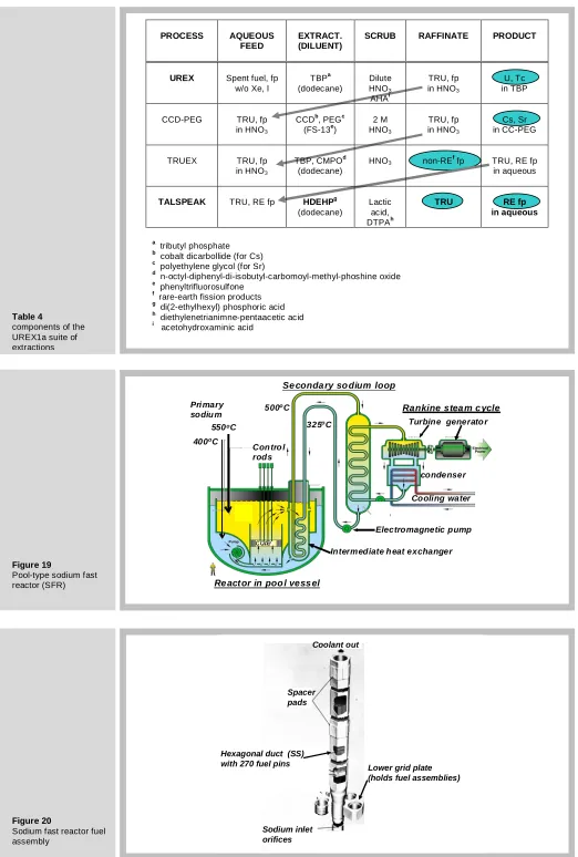
Table 4
components of the UREX1a suite of extractions
Figure 19
Pool-type sodium fast
reactor (SFR) 4 0
550oC
400oC
500oC
325oC
Pri mary sodiu m
Electromagnetic pump Se conda ry so dium loop
Re act or in poo l vess el
Turbine generato r
condenser Rankine stea m c ycle
Cooling water
Intermediate h eat exchanger
core
Con tro l rods
Figure 20
Sodium fast reactor fuel assembly
Hexagonal duct (SS) with 270 fuel pins
Spacer pads
Coolant out
Sodium inlet orifices
Vl. The Sodium Fast Reactor (SFR)
Figure 19 shows the power-generation plant driven by a sodium-cooled fast reactor. As the name implies, the coolant is liquid sodium. Contrary to the loop-type system of the VHTR (Figure. 10), the heat exchanger that receives the energy extracted from the core by the primary sodium and transfers it to a secondary sodium circuit is located in a pool of liquid sodium. The electromagnetic pump pushes sodium coolant up through the core and into a large inside section of the pool where the temperature is about 550oC. The primary sodium exiting the shell side of the intermediate heat exchanger is pumped into the core. The heated secondary sodium drives a second heat exchanger with water in the tube side. This drives an ordinary Rankine cycle to produce electricity. However, an equally-important function of the SFR is to burn the minor actinides and plutonium.
The fuel assembly for the sodium fast reactor is shown in Figure. 20. The hexagonal assemblies, each holding 270 fuel pins, are set into a lower grid plate. They are fixed at the upper part by two spacer pads, which is where each assembly contacts the six surrounding assemblies.
Figure 21 depicts the fuel pin, which is what a fuel rod or fuel element is called in the fast reactor trade. The fuel pin is smaller than the fuel element of a LWR, being only 6.5 mm in diameter. Its cladding is made of a ferritic steel HT9 because this type of steel is much more resistant to void swelling than the austenitic steels such as 3165. HT9 is especially hardened to give it strength normally lacking in ferritic steels.
A noteworthy feature of the SFR fuel pin is the huge (compared to LWR) fuel-cladding gap, the reason for which will be reviewed later. The fuel is an alloy of depleted uranium with 20% of recycled plutonium and 10% zirconium. The last of these elements increases the liquidus temperature and increases the resistance to fuel-cladding interaction. The sodium bond is essential for avoiding excessively-high fuel temperatures.
The fuel pin is rather short – less than 2 m long. About 1 m contains fuel slugs with the sodium bond in the fuel cladding gap. An equally long section is devoted to a plenum to receive released fission gases without overpressurizing the cladding wall. The other noteworthy feature of the fuel pin is the wire wrapping. This serves two purposes. The first is to separate fuel pins. The second is to induce a swirl in the up-flowing sodium coolant to improve convective heat transfer.
6.1 Irradiation effects on metal fuel
Figure 22 shows photomicrographs of cross sections of the fuel pin before and after irradiation. The Zr component of the as-fabricated fuel forms a separate phase in the U-Pu matrix.
After irradiation, a number of profound changes take place. First, there is extensive separation of the elemental components. There are usually three distinct radial zones, but in this case only the low-melting central phase, which is close to the eutectic composition that melts at about 700oC, is formed. Except for the outer surface, the outer annulus of the fuel does not exhibit significant changes.
The right-hand photomicrograph of Fig. 22 reveals extensive fuel-cladding interaction, with the rare-earth fission products and plutonium liquefying the cladding by forming an alloy with iron.
The figure shows that the initial 600 µm radial gap has completely closed. This occurs rather early during irradiation because swelling of the fuel due to fission-gas bubbles is large.
Figure 23 shows the close relation between swelling and fission gas release in metal fuel. Fission gas precipitates into large bubbles very early in irradiation. If the fuel-cladding gap is too small, the swelling fuel exerts an unacceptably-large stress on the
5
cladding. However, at about 33% swelling, the gas bubbles interlink and vent their contents to the plenum. Thereafter, the swelling rate diminishes drastically.
The design compromise is to allow for a gap sufficiently large so that bubble interlinkage and closure of the gap occur simultaneouosly. This requirement is fulfilled with an initial gap thickness if the neighborhood of 600 µm. With this stratagem, burn-ups up to 75% FIMA are attainable, and essentially complete burnup of the minor actinides and plutonium is achieved.
Vll. Pyroprocessing
Instead of aqueous methods, metal fuel is reprocessed by non-aqueous, pyrometallurgical techniques (pyroprocessing) [16]. The motivations are the same as for aqueous reprocessing, namely separation of plutonium and the minor actinides from the other fuel components in order to prepare them for conversion to short-lived fission products . The efficiency of removing fission products from the recycle uranium is much lower than that from the aqueous process. The latter can be handled as if it were uranium from the ground, but the U product from pyroprocessing is sufficiently radioactive that it must be handled in a hot cell.
As Figure. 24 shows, the spent fuel from both LWRs and SFRs are treated by pyrometallurgical methods (electrorefining). The diagram represents an entire fuel cycle except for the enrichment in U-235 required for fuel fabricated for the LWR and the mining, milling and conversion of ore to U metal or oxide. The head-end step for LWR spent fuel is the same as in the UREX process, namely a chop-leach operation that separates fuel from cladding6 followed by conversion of the nitric-acid leach solution containing all elements of the spent fuel to oxides. The oxide must be reduced to metal by reaction with lithium:
2Li + UO2→ 2Li2O + U (14)
The contaminated U product is fed to an electrorefiner which separates uranium, plutonium plus minor actinides and all fission products from each other. The uranium product is recycled to a fuel-element fabrication plant where fuel elements for the LWR(s) are made. The Pu+MA product is fed to a second electrorefiner, which also receives as feed the chopped spent fuel slugs from the SFR. This unit separates out only the fission products; the heavy metals U and Pu and the minor actinides are recycled to the SFR to be burned. Plutonium and the minor actinides never leave the fuel cycle; uranium enters and electricity and fission products come out.
6
if the fuel-cladding gap of LWR fuel were LM-bonded, the chop-leach step would be unnecessary. Since fuel and cladding never come in contact, the spent fuel should simply slip out of the cladding.
42
Gas Plenum
Na in gap
Bottom end cap
Fuel slu gs –91
cm
Wire wrap (HT9)
Cladding (HT) Top end cap
HT9 cladding mm OD mm thick
sodium in gap mm thick
U-20Pu-10Zr 6.5 0.5
[image:23.595.34.557.499.770.2]0.6
Figure 21
43 as-fabricated
Zr-rich phases
Low- Melting Phase
[image:24.595.39.561.40.803.2]La, Ce, Pr, Nd, Pu react with SS cladding
Figure 22
Photomicrographs of SFR fuel before (left) and after irradiation (center and right)
Figure 23
SFR fuel irradiated to FIMA = 0.02
Figure 24
Pyroprocessing of spent fuel from LW Rs and SFRs UO 2-fueled light-water reactor U-metal-fueled fast reactor removal of Zr cladding oxide reduction
U, Pu, MA, fp
Li Li
2O
U, Pu, MA, fp
Electrorefining fuel-element fabrication recycle U fresh U enriched waste treatment fp Electrorefining Pu, MA chop up fuel element
spent fuel spent fuel
U, Pu, MA, fp fuel-element
fabrication fresh U (natural)
U, Pu, MA
fp
geologic disposal
fp = fission products MA = minor actinides (Np, Am Cm)
44 Fuel swelling, %
F is s io n -g a s r e le a s e , % Bubble interlinkage at 33 % swelling
7.1 The Electrorefiner
The electrorefiner, which is the heart of pyroprocessing, is shown in Figure. 25. This could also be called an electrotransporter, meaning that components are separated and moved to different locations. However, it is not electrolytic in the sense that an oxidized and reduced species are produced.
The system consists of an anode in the form of a basket into which are loaded the chopped fuel slugs from the SFR or the recovered metal from the LWR branch. The two cathodes are both at the same potential relative to the anode. The first one is stainless steel and the second one is a pool of liquid cadmium. Another pool of molten Cd occupies the bottom of the steel vessel which also contains the molten LiCl/KCl electrolyte. The eutectic temperature of LiCl and KCl is 350o, so the unit operates at ~ 500oC.
The following separations are effected:
1. U3+ migrates to the first cathode where it is reduced to a very pure metal; none of the other components of the spent fuel co-deposit.
2. Pu3+ and the minor actinide ions, are transported to the second cathode, where they are reduced to metals and dissolve in the Cd pool
3. Alkali metals (Cs) and alkaline earths (Ba, Sr) and the rare earths remain in the electrolyte
4. The noble metals fall to the cadmium pool at the bottom of the vessel.
The thermochemistry of the separation is analyzed below.
7.1.1 Electrode potential
For an adequate rate of electrotransport, the “transportable” metal ion mole fraction in the electrolyte must ~ 0.02 [16]. All transportable ions from dissolution of the anode (see Fig. 25) are trivalent. The standard free energies of formation of the transportable ions at 500oC range from - 55 kcal/mole for UCl3 to -62 kcal/mole for PuCl3. The minor
actinides fall between these values. Taking U as the major component, the anode reaction is:
U → U3+ + 3e
For which the standard electrode potential is obtained from:
o o
f
G
3
∆
= − ℑε
where ℑ is Faraday’s constant. With ∆Gfo = −55 kcal mole/ , this formula yields
εo
= 0.80 V. The applied voltage is equal to the Nernst potential:
3
o
U
RT lna
3 +
ε = ε − ℑ
neglecting non-ideality, aU3+ ≅xU3+ =0.02, so at T = 773 K, ε = 1.0 V. This is the
voltage applied between the anode and the cathodes.
7.1.2 Why Pu doesn’t deposit on the first cathode
The standard free energy of formation for Pu → Pu3+ + 3e is – 62 kcal/mole, so the standard free energy for the reaction:
U3+ + Pu = U + Pu3+
is ∆Go = - 7 kcal/mole. The law of mass action for this reaction is:
3 3
cath salt U Pu
cath salt Pu U
a a 7000
exp 92
1.986 773 a a
+ +
−
= − =
×
For the U-20Pu-10Zr fuel:
3 3
salt salt cath
U
Pu U
a
+≈
0.2a
+a
≈
1
These activities yield an activity of plutonium metal in the uranium deposit of cath
Pu
a
= 0.002 – thus explaining the high uranium purity on the first cathode.7.1.3 How is Pu collected at the liquid Cd cathode?
The Nernst equation for the electrode reaction Pu3++ 3e = Pu(Cd) is:
3
o Pu
Cd Pu
a RT
ln
3 a
+
ε = ε −
ℑ
Where
a
CdPu is the activity of plutonium in liquid cadmium. For the same anode-cathode voltage (ε = 1V) and the standard electrode potential for the Pu/Pu3+ couple (εo = 0.9V) the above equation yields:3
salt Cd Pu Pu
a
+/ a
=
0.13
Pu and Cd form the strongly bound intermetallic compound PuCd6, which reduces the
activity of Pu in the cadmium (but not its concentration) to 4x10⁻⁶. Therefore the activity of Pu3+ in the salt is 0.13x4x10-6 = 5x10⁻⁷. Neglecting nonideality, this is the mole fraction of Pu3+ in the salt adjacent to the second cathode, i.e., essentially zero. Thus the driving force for Pu3+ to be transported to the second cathode is its maximum value. When Pu3+ arrives at the second cathode, it is converted to the intermetallic compound and held in the liquid cadmium.
7.1.4 Why doesn’t uranium collect in the second cathode?
Because it does not form an intermetallic compound as does plutonium.
Mo, Pd, Rh, Ru U, Pu, MA, RE
Cs, Ba, Sr
Unstable
(in Cd pool)
Electro-transportable Stable
[image:26.595.41.560.459.785.2](in salt phase)
Figure 25
Vlll. Summary
The conventional fuel element for LWRs – UO2 fuel, Zircaloy cladding, He bond – has been
in continuous use for 50 years. Recently, economics-driven extension of fuel burnup has resulted in stresses on both the cladding and the fuel. Specific concerns are:
- strain from fission-product-driven swelling fuel
- internal pressurization by fission gas released from fuel - internal stress-corrosion cracking by fission-product iodine - vibration-driven fretting degradation by grid spacers - external corrosion by coolant water
- embrittlement by corrosion-product hydrogen -
Although the probability of cladding failure from these causes during the lifetime of a fuel element is low ( ~ 10-5), the consequences are not (~$1M/day if shutdown of the reactor is required and replacement power must be purchased). Nonetheless utilities and vendors resist even modest changes in fuel, such as a liquid-metal bond to replace helium in the fuel-cladding gap or replacing UO2 or MOX fuel with a U-Zr hydride.
The next generation nuclear plant (Gen IV) is likely to be the very-high-temperature reactor (VHTR). This reactor is fueled by tiny fuel particles (TRISO) embedded in graphite and cooled by helium. This reactor concept promises to deliver outlet coolant at temperatures approaching 1000oC, which would make thermochemical hydrogen production or electrolysis of water economical. The UREX1a reprocessing suite is needed to fulfill the requirements of nonproliferation and to avoid approaching limiting temperatures and site-boundary dose rates in the high-level waste repository. This collection of four distinct solvent extraction steps contained in UREX1a, however, is far from being demonstrated.
Another candidate for the next generation nuclear plant is the sodium-cooled fast reactor (SFR). This reactor is intended to operate in coordination with one or more LWRs in a fuel cycle that accepts only fresh uranium and delivers only fission products and heat (electricity). The minor actinides and plutonium are recycled in the SFR until they are completely converted to fission products.
REFERENCES
1 G. Oudinet, I. Munoz-Viallard, L. Aufore, M. J. Gotta, J. M. Becker, G. Chiarelli, and R. Castelli, "Characterization of plutonium distribution in MIMAS MOX by image analysis," Journal of Nuclear Materials, vol. 375, pp. 86-94, 2008.
2 H. Kleykamp, "Post-irradiation studies on LW R-MOX fuel fabricated by the optimized co-milling process," Journal of Nuclear Materials, vol. 324, pp. 198-202, 2004.
3 J. Turnbull, "A review of MOX fuel and its use in LW Rs," OECD Halden Reactor Project HW R-435, 1995.
4 D. R. Olander and E. Greenspan, "Uranium-zirconium hydride fuel properties," Nuclear Engineering and Design, vol. to be published.
5 M. T. Simnad, "The U-ZrHx alloy: Its properties and use in TRIGA fuel," Nuclear Engineering and Design, vol. 64, pp. 403-422, 1981
6 E. Greenspan "Hydride Fuel for LW Rs - Project Overview," Nuclear Engineering and Design, to be publised.
7 D. W ongsawaeng and D. Olander, "Liquid-metal bond for LW R fuel rods," Nuclear Technology, vol. 159, pp. 279-291, 2007.
8 A. F. Lillie, D. T. McClelland, W . J. Roberts, and J. H. W alter, "Zirconium hydride fuel element performance characteristics," Atomics International Div., Canoga Park, Califlonia, USA AI-AEC--13084, 1973.
9 T. B. Lindemer and T. M. Besmann, "Chemical thermodynamic representation of <UO2 ± x>," Journal of Nuclear Materials, vol. 130,
pp. 473-488, 1985.
10 T. M. Besmann and T. B. Lindemer, "Improvement in the chemical thermodynamic representation of <PuO2 - x> and <U1 - zPuzOw>,"
Journal of Nuclear Materials, vol. 137, pp. 292-293, 1986.
11 C. Guéneau, C. Chatillon, and B. Sundman, "Thermodynamic modelling of the plutonium-oxygen system," Journal of Nuclear Materials, vol. 378, pp. 257-272, 2008.
12 D. R. Olander, in Fundamental Aspects of Nuclear Reactor Fuel Elements: Us Dept of Energy, pp. 181-183, 1976.
13 T. B. Lindemer, "Thermochemical analysis of gas-cooled reactor fuels containing Am and Pu oxides," OAK Ridge National Laboratory ORNL/TM-2002/133, 2002.
14 P. E. Potter, "The uranium-oxygen systems: The ternary systems uranium-carbon-oxygen and plutonium-carbon-oxygen, and the quaternary system uranium-plutonium-carbon-plutonium-carbon-oxygen," Journal of Nuclear Materials, vol. 42, pp. 1-22, 1972.
15 F. J. Homan, T. B. Lindemer, E. L. J. Long, T. N. Tiegs, and R. L. Beatty, "Stoichiometric effects on performance of high-temperature gas-cooled reactor fuels from the U--C--O system," Nuclear Technology, vol. 35, pp. 428-441, 1977.