University of Southern Queensland
Faculty of Health, Engineering and Sciences
OPTICAL ACCESS ENGINE
DEVELOPMENT
A dissertation submitted by:
Kevin Dray
Abstract
A partial design for an optical access engine was acquired by the University of Southern Queensland from Oxford University in the UK. It is the desire of USQ or specifically certain faculty members to include an optical access engine in their engines laboratory.
The purpose of this research project is to take the existing partial design from the early 1990’s of Professor Richard Stone’s (Oxford University) and develop it into a useable design of which the University can invest in. for their laboratory.
Due to time constraints it was not possible for the entire engine to be designed and detail drawings produced so the engine was designed from the bottom end up to the top of the optical bore which on a normal engine is the top of the cylinder block.
Included in this dissertation is a report covering the need for engine research and the place of optical access engines in research. A literature review of various optical access engines and discussion of their types and uses. Finally a report covering the methodology of the design and the results of design calculations with a focus on balancing and component design. Detail drawings suitable for workshop manufacture and calculations are included as part of this dissertation as are recommendations for future work.
University of Southern Queensland
Faculty of Health, Engineering and Sciences
ENG4111/ENG4112 Research Project
Limitations of Use
The Council of the University of Southern Queensland, its Faculty of Health, Engineering & Sciences, and the staff of the University of Southern Queensland, do not accept any responsibility for the truth, accuracy or completeness of material contained within or associated with this dissertation. Persons using all or any part of this material do so at their own risk, and not at the risk of the Council of the University of Southern Queensland, its Faculty of Health, Engineering & Sciences or the staff of the University of Southern Queensland.
This dissertation reports an educational exercise and has no purpose or validity beyond this exercise. The sole purpose of the course pair entitled “Research Project” is to contribute to the overall education within the student’s chosen degree program. This document, the associated hardware, software, drawings, and other material set out in the associated appendices should not be used for any other purpose: if they are so used, it is entirely at the risk of the user.
University of Southern Queensland
Faculty of Health, Engineering and Sciences
ENG4111/ENG4112 Research Project
Certification of Dissertation
I certify that the ideas, designs and experimental work, results, analyses and conclusions set out in this dissertation are entirely my own effort, except where otherwise indicated and acknowledged.
I further certify that the work is original and has not been previously submitted for assessment in any other course or institution, except where specifically stated.
K.Dray (0011120331) (30/10/2014)
TABLE OF CONTENTS
Abstract ii
Limitations of Use iii
Certificate of Dissertation iv
Table of Contents v
Glossary of Terms viii
Mathematical Nomenclature xi
1.0 Introduction 1
1.1 Background 1
1.2 Role in Combustion Research 2 1.3 USQ Optical Access Engine Project (Background) 3
1.4 Project Aim 3
1.5 Scope of Work 3 1.6 Conclusion 4 2.0 Literature Review 6 2.1 What is an Optical Access Engine 7 2.2 Applications 8
2.3 Existing Optical Access Engine Designs 9 2.4 Bowditch Piston Arrangement 15
2.5 Optical Access Engines (Cutting Edge) 16
2.6 The USQ Optical Access Engine 18
2.7 Engine Design 19
3.0 Methodology 21
3.1 Engine Balancing 22
3.1.1 Balancing Theory 22
3.1.2 Slider Crank Kinematics & Engine Balancing 28
3.1.3 Virtual Balancing 32
3.2 Crankshaft Design 34
3.2.1 Gas Pressure 35
3.2.2 Conrod Forces 39
3.2.3 Application of Design Paper 41
3.2.4 Additional Design Checks F.E.A 49
3.3 Conrod Design 50
3.3.1 Stress Analysis 51
3.3.2 Fatigue Analysis 52
3.3.3 Buckling Analysis 54
3.3.4 F.E.A. 55
3.4 Bearing Design 56
3.4.1 Main Bearings 57
3.4.2 Big End Bearing Design 59
3.4.3 Little End Bearing Design 60
3.4.4 Counter Balance Shafts 61
3.5 Piston Design 62
3.5.1 Piston Material 63
3.5.2 Rings Sleeve Material 64
3.5.3 Window Material 64
3.5.4 FEA Load Cases 65
3.6 Fly Wheel Design 68
3.7 Optical Bore Design 68
3.8 Drafting and Communication 68
4.0 Results & Discussion 4.1 Engine Balancing 71
4.1.1 Slider-Crank Simulation 71
4.1.2 Simulation vs Theoretical Conclusions 74
4.1.3 Balance Shafts 74
4.2 Crankshaft 74
4.2.1 Design Paper Results 74
4.2.2 FEA Results 75
4.2.3 Discussion of Revision A 77
4.2.4 Further Results – Revision B 79
4.2.5 Final Discussion 81
4.3 Conrod 82
4.3.1 Little End Bearing Eyelet 82
4.3.2 Buckling 86
4.3.3 Further Results (Redesign) 87
4.3.4 Discussion of Results 90
4.4 Bearings 91
4.4.1 Main Bearings 91
4.4.2 Big End Bearing 93
4.4.3 Little End Bearing 94
4.4.4 Balance Shaft Bearings 94
4.5 Piston 96
4.5.1 Window Design 96
4.5.2 Material Selection 97
4.5.3 FEA Results 97
4.5.4 Redesign and Further Results 101
4.6 Final Balancing 104
4.6.1 Crankshaft Balancing 104
4.6.2 Final Shaking Forces 106
4.7 Conclusion of Results 110
5.0 Conclusions 112
5.1 Project Compliance 112
5.2 Material Availability 112
5.3 Final Balancing Results 113
5.4 Temperature Limitations 114
5.5 Operating Limitations 114
Future Work 115
References 118
Appendices 122
Appendix A -Project Specifications 123
Appendix B -Design Calculations 124
Appendix C -Selection of Detail Drawings (A4) 161 Appendix D -Full Detail Drawings (A3) N/A Appendix E -Materials Spreadsheet N/A
GLOSSARY OF TERMS
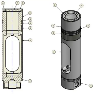
Figure 1 – Main assembly section view & isometric view.
ITEM DESCRIPTION QTY
1 MAIN CRANKCASE 1
2 DRIVE ATTACHMENT 1
3 SIDE COVER (OIL FILL) 1
4 TIE ROD 6
5 FLYWHEEL SIDE MAIN BEARING HOUSING 1
6 ENCODER SIDE MAIN BEARING HOUSING 1
7 FLYWHEEL 1
8 COUNTER BALANCE SHAFT 4
9 COUNTER BALANCE SHAFT WASHER 8
10 PRIMARY BALANCE WEIGHT 2
11 SECONDARY BALANCE WEIGHT 2
12 COUNTER BALANCE SHAFT SPACER LONG 4
13 COUNTER BALANCE SHAFT SPACER SHORT 4
ITEM DESCRIPTION QTY
15 PRIMARY COUNTER BALANCE SHAFT GEAR 1
16 CRANKSHAFT DRIVE PINION 1
17 PRIMARY COUNTER BALANCE SHAFT GEAR 1
18 SECONDARY COUNTER BALANCE SHAFT GEAR 1
19 BEARING CAP (PRIMARY, FLYWHEEL SIDE) 2
20 6040DU - LEAD/PTFE BEARING (MODIFIED) 2
21 THRUST COLLAR 1
22 OIL SUPPLY FITTING 1
23 ENCODER ATTACHMENT 1
24 CRANKCASE SIDE COVER 1
25 SECONDARY COUNTER BALANCE SHAFT GEAR 1
26 LOWER BARREL 1
27 LOWER CYLINDER SLEEVE 1
28 BIG END LOWER HALF 1
29 CONROD 1
30 ENGINE CRANKSHAFT 1
31 LITTLE END BEARING 1
32 PISTON EXTENSION 1
33 PISTON HEAD 1
34 OPTICAL WINDOW COLLAR 1
35 LOWER PISTON 1
36 CRANK BALANCE WEIGHT 2
37 SLIDING BUSH 2
38 LOW FRICTION PISTON RINGS 2
39 WRIST PIN 1
40 UPPER BARREL 1
41 OPTICAL ACCESS COLLAR 1
42 MAIN ENGINE ASSEMBLY 4
43 MAIN ENGINE ASSEMBLY 1
44 OPTICAL ACCESS SLEEVE 1
45 OPTICAL ACCESS WINDOW 1
46 WC60DU - LEAD/PTFE THRUST BEARING (MODIFIED) 2
47 4x12 MACHINE DOWEL 4
48 5 x 20 MACHINE DOWEL 4
49 12 x 20 MACHINE DOWEL 2
50 1/4" BSPT PRESSURE PLUG 2
51 2.5 x 12 MACHINE DOWEL 2
52 4 x 20 MACHINE DOWEL 9
53 COUNTER BALANCE SHAFT BEARING 4
54 COUNTER BALANCE SHAFT BEARING 4
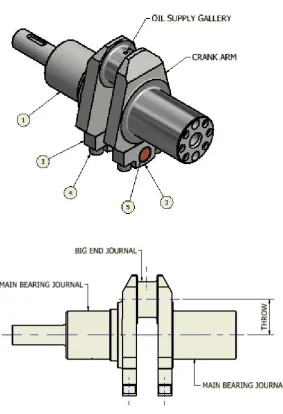
Bowditch Piston Assembly
[image:10.595.139.465.125.455.2]
Figure 2 –Bowditch piston assembly section view & isometric view (Design revision A) Final design may differ slightly.
ITEM DESCRIPTION QTY
1 PISTON EXTENSION 1
2 PISTON HEAD 1
3 OPTICAL WINDOW COLLAR 1
4 LOWER PISTON 1
5 SLIDING BUSH 2
6 LOW FRICTION PISTON RINGS 2
7 OPTICAL ACCESS WINDOW 1
8 4 x 20 MACHINE DOWEL 4
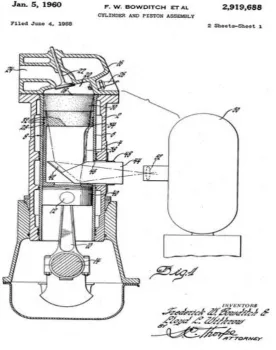
Crankshaft Assembly
[image:11.595.123.407.99.514.2]
Figure 3 – Crankshaft assembly side view & isometric view. (Design revision A) Final design may differ slightly.
ITEM DESCRIPTION QTY
1 ENGINE CRANKSHAFT 1
2 4 x 20 MACHINE DOWEL 4
3 CRANK BOB-WEIGHT 2
4 BROACHED SOCKET HEAD CAP SCREW - METRIC - 4
5 TUNGSTEN INSERT 2
General Terms
No. Term Description
1 ATDC Crank position After Top Dead Centre
2 BDC Bottom Dead Centre - Lowest position of piston
3 BTDC Crank position Before Top Dead Centre
4 Expansion Phase Portion of the power stroke after combustion
5 FEA Finite Element Analysis - Computer Stress Analysis
6 ICE Internal Combustion Engine
7 OAE Optical Access Engine
8 OHV Overhead Valves - Engine valve configuration
9 TDC Top Dead Centre - Highest position of piston
10 Compression Phase Portion of the compression stroke before ignition
11 Counter Balance Shaft
Separate rotating shaft to counter reciprocating inertia forces
12 HCCI Homogeneous Charge Compression Ignition
13 Optical Bore Upper cylinder sleeve made from transparent quartz
14 Journal Shaft component of a bearing arrangement
15 Oil Bore
Hole in the crankpin to which oil feeds the big end bearing
16 DOHC Double Overhead Cam
Mathematical Nomenclature
The nomenclature listed below covers that used in this dissertation body only and does not extend to the detailed calculations contained in the appendix. Whilst all efforts have been made to maintain a consistency it was not possible to use the exact same nomenclature in the design software.
Term Description Units
Reciprocating mass kg
Crank throw m
Piston position m
Piston velocity m/s
Piston accelerations m/s^2
ω Angular Acceleration radians/s
θ Crank Angle radians
Vertical reciprocating force N
Upper conrod equivalent mass kg
Conrod mass kg
Term Description Units
Lower conrod equivalent mass kg
Piston mass kg
Upper conrod mass radius m
Lower conrod mass radius m
First order reciprocating forces N
Second order reciprocating forces N
Horizontal forces due to bob-weight N
Effective bob-weight mass kg
Bob-weight mass radius kg
Crankshaft & lower conrod mass (excl. bob-weight) kg
Shaking torque N.m.
Primary balance weight kg
Secondary Balance weight kg
Primary balance weight radius m
Secondary balance weight radius m
φs Stoichiometric ratio
φe Equivalence ratio
γ Poly=tropic constant
ax Weibe function constant
mx Weibe function constant
Burnt fuel constant Mass burn fraction
Final gas temperature (combustion) K
Initial charge temperature K
Mass of fuel kg
Heating value of fuel kj/kg
Specific heat value of air (constant volume) kj/kg.K
Final cylinder pressure Mpa
Initial cylinder pressure MPa
Initial cylinder volume M^3
Initial gas temperature M^3
Final cylinder volume M^3
Piston gas force with respect to crank angle MPa Cylinder pressure with respect to crank angle MPa
Piston diameter M
Conrod angle Radians
Conrod force with respect to crank angle N
Axial force in the web N
Angle between conrod and crankarm Radians
Moment in the crankpin at the oil bore N.m.
Angle of the oil bore to the crankpin tangent Radians
Term Description Units
Alternating bending stress in the web MPa
Bending moment in the web N.m.
Alternating compressive stress in the web MPa
Alternating bending stress at the oil bore MPa
Axial torque in the main journal or crankpin N.m.
Alternating torsional stress MPa
Torsion modulus of the main journal mm^3
αb Crankpin fillet bending stress factor
αt Crankpin fillet torsion stress factor
βb Journal fillet bending stress factor
βt Journal fillet torsion stress factor
βq Journal fillet radial compression stress factor
γb Crankpin oil bore bending stress factor
γt Crankpin oil torsion stress factor
Factored alternating bending stress in crankpin fillets MPa Factored alternating bending stress in crankpin oil bore MPa Factored alternating bending stress in main bearing fillets MPa Alternating torsional stress in crankpin fillets MPa Alternating torsional stress in the main bearing fillets MPa Alternating torsional stress in the crankpin oil bore MPa Equivalent alternating stress in the crankpin fillet MPa Equivalent alternating stress in the main bearing fillet MPa Equivalent alternating stress in crankpin oil bore MPa
Fatigue strength for the crank pin MPa
Fatigue strength for the main bearing MPa
Minimum material tensile strength MPa
Acceptability factor
Mean Stress (Fatigue Analysis) MPa
Alternating Stress (Fatigue Analysis) Mpa
Endurance stress Mpa
Fatigue factor of safety
Conditions constant for conrod buckling (Roark's) Sommerfeld number
Conrod angular velocity Radian/s
ωcr Crankshaft angular velocity Radian/s
Relative angular velocity of the conrod to the crankpin Radian/s
Angular velocity of the load Radian/s
Balance mass radial force N
Bearing life (90th percentile) hr
Per unit bending stress in optical window N
Chapter
1
Introduction
As the report title suggests this project involves the research of Optical Access Engines and the design of (at least in part) of an Optical Access Engine for the University of Southern Queensland’s engine laboratory.
What is an Optical Access Engine? Put simply an Optical Access Engine is an engine (in this case a reciprocating internal combustion engine) where the combustion process can be viewed from outside the engine body. The means of doing this has changed over the years, however in modern engine designs this is currently achieved by viewing the process through a transparent piston crown and mirror positioned at 45° to the path of the piston. See figure 1.1 for a better understanding.
It is important to note that it is assumed in this report that the reader possesses a basic understanding of the operation of an internal combustion engine. Specifically a spark ignition, petrol engine as found in most cars these days. To learn more about the internal combustion engine the reader is referred to the following excellent texts: Introduction to Internal Combustion Engines by Richard Stone, Internal Combustion Engines Fundamentals by J.B. Heywood, Internal Combustion Engines by Colin R Ferguson.
1.1 Background: The need for on-going research.
Why perform engine research? In short to further engine development. The internal combustion engine since its inception into general use around the Mid-19th century (Stone,1999) has undergone a myriad of design changes.
By developing engine technology, gains can be made on many fronts (efficiency, performance, reliability, new designs/prototypes and possibly new or modified fuels).
There is a belief that fossil fuels cannot be consumed at their current rates, this leads to the need for more efficient engines to be created and engine/combustion research is a means to achieve this.
Further to the previous statement, emission standards in most countries become stricter by the year (Johnson, 2006), this forces manufactures to design & build cleaner emission engines and the only means to do this involves engine / combustion research.
1.2 The Optical Access Engines Role in Combustion Research.
Possibly the first optical access engine could have been created by Nicolaus Otto when developing one of his prototype internal combustion engines. The optical access component consisted of a glass cylinder sleeve simply to view the mechanical process, however the concept is there.
In the 1930’s General Motors engineers Rassweiler & Withrow were utilizing quartz windows in the cylinder heads and high speed cameras of the time to study combustion in an attempt to solve the engine knock problem (Richter,2008).
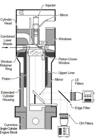
[image:16.595.159.436.402.753.2]In 1960 Fred Bowditch & Lloyd Withrow at General Motors patented an engine design including an elongated piston with an opening in the trunk to place a 45° mirror bolted to the engine block. Included in the head of the piston was a transparent quartz window allowing the combustion process to be viewed from beneath via the 45° mirror (see below).
Figure 1.1: Bowditch Piston Patent Application Drawing (Google Patents, 2012)
It is this basic design applied to a modern engine that is the concept behind our optical access engine design.
As said optical access engines are by no means a new concept, however their use in engine research has increased in recent years. With improvements in high speed camera technology, pressure transducers, IR cameras and the diagnostic functions of lasers the research possibilities of these engines is greater than ever before.
1.3 The USQ Optical Access Engine Project (Background)
An existing optical access engine design (in part) was provided to USQ from Oxford University and specifically Professor Richard Stone. The design is Professor Stone’s from the early 1990’s and consists of various general arrangement and detail drawings mostly of the crankcase and counter balance shafts required to counter the various shaking forces produced. The package also included what appeared to be detail drawings of parts from existing stationary engines. This was concluded from the presence of part numbers on the drawings. It is possible these parts were intended for use in the original optical access engine design.
It needs to be mentioned that the design package acquired was incomplete and unverified. Numerous drawings were missing/incomplete eg: bowditch piston, upper cylinder, cylinder head and associated parts to name a few. Also there was no complete document transmittal, design calculations or material specifications.
1.4 The Project Aim
The project task is to transform this incomplete package into a working design. Something the University can invest in for their engine laboratory and proceed to manufacture. This would include producing general arrangement drawings, detail or workshop drawings, design calculations verifying the design, material specifications (included in the drawings) and virtual simulation / finite element analysis to supplement the calculations.
To summarize the aim: Take the existing design as provided and transform it into a complete and usable design package.
1.5 Scope of Work
A shortened itemised list of contributions made to this project is given below,
1. Review & interpret the original design package provided by Prof. Stone
2. Model the existing design in 3D CAD software (Autodesk Inventor)
3. Determine the parts requiring design verification
4. Determine the parts missing from the package provided and parts requiring redesign due being designed by engine manufactures with tooling and production facilities unavailable to USQ.
5. Design the required parts: Bowditch piston, wrist pin, crankshaft, conrod, big end bearing, little end bearing, upper cylinder. 6. Perform engine balancing calculations and virtual simulation to
verify
7. Design verify the required remaining parts
8. Produce assembly and detail drawings for manufacture.
Extensive research was required to perform a number of these tasks, knowing what features were typical in an optical access engine needed detailed research as did the materials used for certain parts (PTFE rings, Quartz widows etc.)
As mentioned a number of components were missing from the provided package and required designing. Designing these, the verification of existing and new components along with engine balancing and drawing production were the main contributions made.
An important requirement of this design and thus a design constraint was the final design needs to be produced in a general workshop. Complex manufacturing processes could not be part of the production requirements and therefore final design needed to account for this.
1.6 Conclusion
To date this project has involved engine research with a focus on existing optical access engines, research into engine balancing specifically single cylinder engines, mechanical component design with a focus on designing for infinite life (fatigue) and plain bearing design with a focus on hydrodynamic bearing conditions.
Extensive material research has been performed to select both suitable and available materials for each designed component factoring in the workshop limitations.
All this has led to the complete design of the engine bottom end up to the top of the piston and barrel. The crankshaft and conrod was redesigned using the original drawings as a guide but increased in strength and modified to better suit fabrication in a general machine shop. The piston and upper cylinder have been designed from scratch utilizing extensive research into materials, optical access designs and clearances.
Lastly all remaining parts were utilized from the design package and only minor modifications performed as a result of verification calculations, balancing requirements and parts / materials availability.
The focus of this dissertation will be discussing the new component design, existing component verification, engine balancing and design considerations / limitations. The literature review will outline other optical access engines, their place in industry, features, manufacturers and where the USQ optical access engine fits in.
It was originally hoped to reach the point of design where the head from an existing engine would be married up to the cylinder block of the new design. Unfortunately time constraints have caused this project to fall just short of this point and it is hoped that another student will continue the design pass this point.
A set of detail drawings and design calculations can be found in the appendices.
Chapter
2
Literature Review
The automotive industry has been utilizing optical access engines for a number of decades as a tool to assist in finding solutions to their development problems and meet ever changing emission specifications. Universities conducting research and education have also been using optical access engines for several years now to study the combustion process and educate students.
Engine and combustion research is driven by the need to improve existing designs, manufacturers are pressured by the market and governing bodies to improve emissions and fuel economy.
If the global increase in car sales continues with global sales topping 80 million in 2013 up 4.2% on 2012. (CNBC, 2014) and 92% of consumers rate fuel efficiency a top priority when purchasing a new car (KPMG, 2014). A continuing focus on engine research by manufactures seems a logical outcome to meet the ever tightening emission controls imposed by governments countering pollution due to an increase in the number of vehicles and the demands of consumers for more efficient vehicles. This is validated by the belief of 76% of automotive industry executives that internal combustion engine downsizing is a key issue for future development and 46% plan to invest in internal combustion engine downsizing more than any other power train technology investment. (KPMG, 2014)
To summarize –Legislative and consumer pressures are driving manufactures toward producing more efficient engines with complex control. Many of these new engines have benefited from optical research engines to develop these technologies. (Allen, J, et al., 2000).
This sets the scene as to the relevance of engine research for the domestic sales market alone, the place of optical access engines in engine research is wide spread. A number of papers can be read with respect to engine research using optical access engine on the SAE (Society of Automotive Engineers) digital library. Research topics include laser diagnostics and optical measurement techniques, characterization of combustion, piston
temperatures, fuel sprays and fuel-air mixing to name a few in a variety of engine types eg: SIDI, CIDI, LPG engines and more.
Research into existing optical access engines has been explored in SAE Technical Papers (Carling et al, 1999, Catapano et al, 2011, Steeper et. al, 2000, Weinrotter et al. 2005, Aronsson et al. 2011, Liu et al. 2014) and more. Mechanical design & engine research has been explored in textbooks (Stone, 1999, Norton 2000, Budynas et al. 2012, Young et al. 2012).
2.1 What is an optical access engine?
As mentioned in the introduction an optical access engine is an engine where the combustion process can be observed from outside the engine. Unfortunately this description doesn’t paint a clear picture as to what an optical access engine is and what types there are.
Through the reading of numerous engine research publications it has been derived that there are only four commonly and possibly only used methods of gaining optical access to the combustion chamber of an I.C.E. (Internal Combustion Engine).
[image:21.595.209.406.444.724.2]1. Bowditch Piston (Transparent Crown) 2. Transparent Cylinder Liner (Optical Bore) 3. A Transparent Window in the Head 4. Endoscopic probe
Figure: 2.1: Schematic diagram of a diesel optical access engine. Including Bowditch piston, 45° mirror, upper cylinder windows & optical access window in the cylinder head. (RW Carling et al., 1999, p2)
Although it is possible utilize all four methods on a single engine, modern engines using overhead valves & particularly multi-valve engines all but eliminates the use of the third method. Referring to 2.1left you can see the top end of an optical access engine in cross section, the extended piston with a transparent crown is a Bowditch piston. The combustion in the chamber can be viewed using the 45° shown at the bottom of the piston. Optical access and laser application can also be achieved using the transparent window at the top of the cylinder. In most research laser diagnostics are applied through the top transparent sleeve and the imaging equipment receives through the bowditch piston and mirror arrangement. In this figure there is an example of an optical access window in the head however it’s is far more common to apply an endoscopic probe through the head instead.
To paint a historical picture transparent cylinder heads (or at least heads containing a viewing window) were all that was in use up to the 1960(s), however were always limited by the fact that their size with respect to the cylinder was restricted by the engine valves (assuming an OHV engine) and where the head design was the focus of the research a new window need be fitted with every new cylinder head (Bowditch, F et al, 1958).
By far the most common arrangement is the bowditch piston and transparent upper cylinder liner, it is common to include an endoscopic probe for research purposes, papers by (Catapano, Sementa & Vaglieco, 2011) mention the use of endoscopic probes for optical research in their “Design for a multi- cylinder hi-performance engine GDI engine”. Similarly (Kong, Ricart & Reitz, 1995) utilize an endoscopic probe to acquire luminous flame images from the combustion chamber for research into “In-cylinder diesel imaging compared with numerical computations”.
The vast majority of engine research papers found in the SAE digital library utilizing optical access regardless of whether a petrol or diesel engine was the focus of the research used a combination of a bowditch piston and transparent upper cylinder liner. In no case where laser diagnostics were applied was a transparent upper cylinder liner/window not used.
2.2 Applications
Optical access engines are a tool for research and in the case of universities both research and education. This is clear by the fact that virtually all are utilized in research laboratories be it private research facilities such as the General Motors Collective Research Laboratories or a university laboratory. Their primary use within research is for the purpose of combustion research and engine behaviour.
General Motors Collective Research Laboratories claim to apply and develop optical diagnostics as a means to reveal the physical understanding and
factors limiting the implementation of novel combustions modes such as Homogeneous Charge Compression Ignition (HCCI) & spray-guided direct-injection stratified charge. Such research and development is carried out by GM at their dedicated optical engines laboratory and in conjunction with the University of Michigan. (University of Michigan, 2009).
Many Universities choose to construct their own optical access engine (USQ for example) not only here in Australia but all over the world. A simple google search on the topic will find institutions such as Michigan State University, Melbourne University, Massachusetts Institute of Technology, Oxford University, Technische Universiteit Eindhoven to name only a few. Numerous research papers have been written, specializing on various aspects of engine combustion research using optical access engines. A large number of these papers can be found in the SAE digital library. Such research has involved engine types such as petrol or diesel, turbo or naturally aspirated, direct injection or premixed, large bore or small, swept volumes of 0.3L to 2.5L.
Most research is performed on engine sizes (swept volume) of the intended target. This is to say that research on GDI (Gasoline Direct Injection) engines would be aimed at typical automotive engines (cars) and therefore the swept volume of the research engine would be around 0.5L. This would cover a 2.0L engine if a four cylinder and a 3.0L engine if six.
The Sandia National Laboratories constructed a DISI (Direct injection Spark Ignition) optical access engine for combustion research which was the focus of their paper “Characterization of combustion, piston temperatures, fuel sprays & fuel-air mixing in a DISI optical engine”. The engine they constructed possesses a cylinder swept volume of 0.565L.
Another engine constructed was by the Catapano, Sementa & Vaglieco of the Vienna University of Technology, their design is a four cylinder in-line engine of 1750cc total displacement giving an individual cylinder swept volume of 0.438L. Both engines were spark ignition petrol engines as it is intended our engine will be and the cylinder swept volume will be 0.458L when built.
2.3 Existing Optical Access Engine Designs.
As previously mentioned there are a great number of optical access engines in use in various research & educational laboratories. To give a better idea of what makes up an optical access engine particular designs and their details shall be discussed.
The “Design for a multi- cylinder hi-performance engine GDI engine” paper by Catapano, Sementa & Vaglieco, 2011 describes in detail their design, construction and operational results.
This team basically took an existing 4 cylinder 1.8L turbo GDI engine of undisclosed make and converted it into a complete multi-cylinder optical access engine. Where this design differs from most engine designs researched is that although multi-cylinder engines are often utilized in the construction of an optical access engine (for various reasons discussed later) they are not commonly converted so that all cylinders are optically accessible.
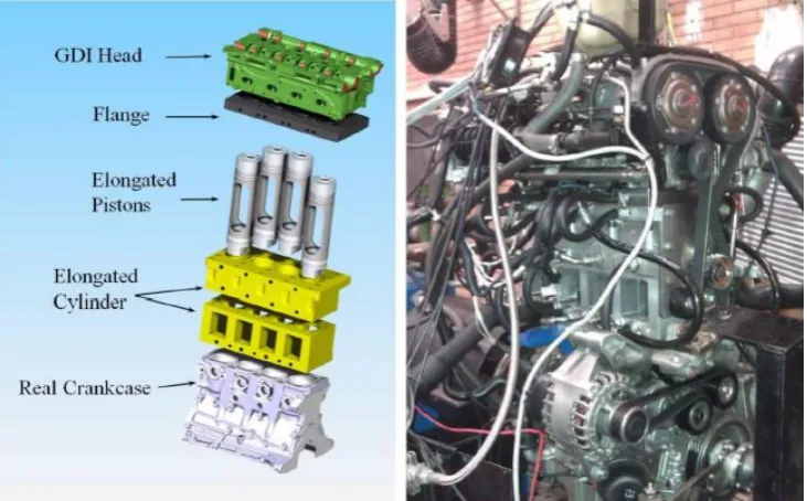
[image:24.595.114.480.321.548.2]The designers Catapano, Sementa & Vaglieco state in their paper the design objectives of avoiding modifying the operational characteristics of the real engine, constructive simplicity, and the thermo-fluid dynamic behaviour of the real engine remaining unchanged thus avoiding the usual brevity of optical engine running tests as reasons for designing the engine in such a fashion.
Figure 2.2: Left: Exploded model view of the multi-cyl optical research engine. Right: Actual engine on test bench in laboratory (Catapano F et al., 2011)
The above configuration of the engine is clear where the basic engine design has been modified as little as possible. Viewing of the combustion process and receipt of the laser images for analysis via the 45° mirror is through the square openings at the bottom of the elongated cylinder block. The laser sheeting is applied through quartz windows built into the flange and the endoscopic probe used as another optical access device is fitted to the GDI (not shown).
Another feature of this design, although not unique it is less common, is that engine powers itself as a typical engine does. With the exception of the
optical access features (Bowditch piston, elongated cylinder, flange/window & probe) this engine is a typical car engine.
Many optical research engines do not run as engines but are turned over by a coupled drive usually an electric motor. The cylinder is then fired on alternate cycles, even every third or so cycle to control operating temperatures (skip fire routine). This approach was taken by (RR Steeper,et al., 2011) seen below and validated as an acceptable method for achieving suitable piston temperatures and combustion performance with respect to a real engine situation.
All optical research engine designs must address engine balancing as all engines generate shaking forces as a product of operation. Unbalanced engines generate excessive shaking forces that influence the research apparatus. The engine used in the Catapano, Sementa & Vaglieco design is a four cylinder in-line engine and thus is already balanced for the first order forces of inertia (forces in phase with engine RPM).
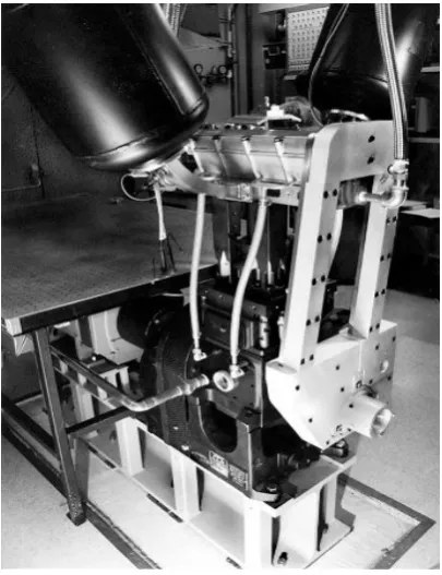
[image:25.595.221.424.466.730.2]The engine design used by Richard R Steeper & Eric J Stevens of Sandia National Laboratories for the research paper “Characterization of combustion, piston temperatures, fuel sprays & fuel-air mixing in a DISI optical engine” seen in figure 2.3 was a single cylinder engine utilizing two balance shafts to counter the primary inertia force generated by the engine motion. These shafts were additionally weighted using tungsten alloy to counter the additional forces due to the heavier bowditch piston (RR Steeper,et al., 2011).
Figure 2.3: View of a single cylinder DISI optical research engine used by Sandia Laboratories. (RR Steeper et. al, 2000)
A common approach particularly by universities when constructing research engines is to take an existing multi-cylinder engine and remove the head of all but the optical access cylinder. The optical access cylinder is then constructed as intended for the experiments and the whole arrangement is driven by an electric motor. This provides effective balance against the shaking force of the engine turning over and reduces the amount of investment in designing and constructing the bottom end of the engine. This approach was employed by Maunoury, Duverger & Mokaddem (2002) in their research paper “Optical Investigation of Auto-Ignition in a small DI Diesel Engine” where a Peugeot 2.0L 4 cylinder diesel engine was used. Another team (Weinrotter et al. 2005) used an in-line six cylinder Scania D12 diesel engine for their research paper “Optical Diagnostics of Laser-Induced & Spark Plug-Assisted HCCI Combustion”
[image:26.595.122.482.443.702.2]It is important to note that all designs employ high pressure transducers, thermocouples and rotary encoders to map cylinder pressure, temperature, visual imaging and laser diagnostics to the crank angle. Referring to the paper (Lui et al., 2014) on the effects of charge homogeneity & repeatability on particulates using the PLIF technique in an optical DISI engine an example can be seen of the diagnostics results being represented with respect to crankangle below.
Figure 2.4: Results from single cylinder DISI optical research engine shown with respect to crank angle; engine used by Brunel University. (Lui et al., 2000)
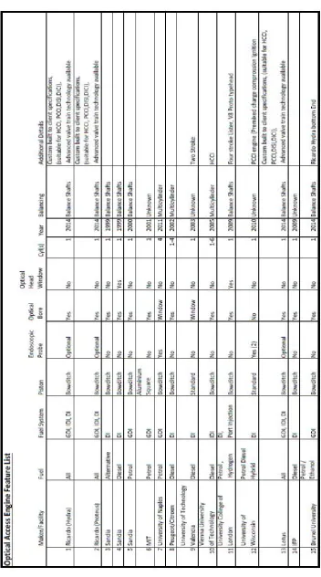
To assist in gaining perspective as to what optical access engines are being constructed (ie: petrol/diesel, single-cyl/multi-cyl) both by OEM(s) such as Ricardo or institutions such as Brunel University, a table has been constructed consisting of the optical research engines reviewed in the process of researching this project.
It is important to note that most of the engines reviewed were not part of design papers but combustion research papers and the engine details were taken from the methodology or setup chapters of these papers. Also added to the list are the leading OEM of optical access engines products for perspective into what is being used, there are numerous laboratories using the Ricardo and Lotus packages for research and thus form part of the greater picture.
From thetable 2.5it can be seen that there is a wide mix of petrol and diesel engines in use for research. This is logical as both engines are in wide use in the automotive industry and it is therefore expected that they would be the focus of much research, especially considering 46% of automotive industry executives plan to invest in ICE downsizing more than any other power train research (KPMG,2014). The use of hydrogen and alternative fuels is in more common use with newer research engines, this can be attributed in part to increased knowledge of hydrogen combustion and alternative fuels use in newer combustion modes such as HCCI, Low Temperature Combustion & Controlled Auto-Ignition.
Another detail to note from table 2.5 is the use of the bowditch piston, virtually all optical research engines use this configuration & a large number employ the optical bore or an optical window. This can be attributed mostly to the use of laser diagnostics and in the case of the Sandia, Ricardo & Lotus engines as a means of viewing the injection phase & charge compression dynamics using hi-speed imaging.
Table 2.5: Table of features covering various optical access engines. Taken from manufactures datasheets and SAE research papers.
2.4 The Bowditch Piston Arrangement
Referring back to Figure 1.1 (Introduction) and also Figure 2 (glossary) the transparent window crown, elongated body and skirt opening can be seen, these are the key features of the bowditch piston. Situating a mirror mounted to the barrel inside the piston cavity allows the viewing of the combustion process above the piston. As can be seen in the image below where the intake and exhaust valves can be seen in the mirror.
[image:29.595.120.461.200.436.2]
Figure 2.6: Left: Rear view of an optical access engine, bowditch piston and bowditch mirror. Valves are visible in the mirror. (RR Steeper et. al, 2000)
Right: Example of a bowditch piston, note the elongated opening and crown. (Catapano F et al., 2011)
The amount of elongation or additional length to the piston is a function of the size of the mirror used and the stroke of the engine, clearly the mirror is not allowed to foul on the operating piston. Additional length to the piston can also be a result of the crown being raised to prevent the rings from operating on the transparent liner as is the case shown above right taken from (Catapano F et al., 2011)
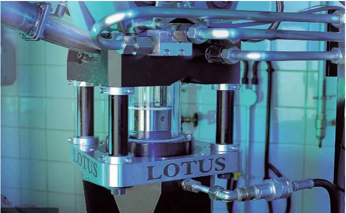
Some Bowditch piston and optical bore designs allow the rings to run in the quartz cylinder liner, this requires thick cylinder walls and sleeves longer than the sum of the engine stroke and depth of the rings from the piston crown so that the rings do not cross over the joint between the optical bore and the lower cylinder. This approach is quite common particularly where the users wish to view more than simply the combustion phase of engine operation. Examples of this approach can be found in figure 2.6 above and the Lotus engine below in figure 2.7.
When designing the piston arrangement allowance must be made for lubrication particularly in the upper cylinder region as no lubricating oil reaches the upper piston skirting. The highest friction occurs at the rings due to cylinder pressure assisting the rings in sealing by applying pressure in an outwards direction on the inside ring face. To deal with this in standard engines compression rings are made as thin as possible and cross hatching the cylinder bore allows small quantities of oil to remain and reduce the friction between the ring face and cylinder. In an optical access engine using a bowditch piston this is not possible as no oil reaches the upper cylinder.
To deal with this hi-temperature polymer rings are used, the plastic to metal or quartz friction co-efficient is quite low and any resulting wear occurs mostly on the rings which are easily replaceable. Another advantage to using polymer rings is reduced bore scuffing, this is important where a long optical bore is used to prevent reduction in optical access quality. Catapano F et al., 2011 used Carbon PTFE and Bronze PTFE as their ring materials whilst (Rosati, MF et al. 2009) used Torlon™ as the ring material.
2.5 Optical Access Engines (Cutting edge)
Who is at the cutting edge of optical access engine design and engine research is hard to know for certain as most companies guard their intellectual property tightly. However several companies offer optical access engine/research engine packages for sale to institutions wishing to perform research, such packages are certainly current technology by today’s definition.
Two well-known market suppliers of Optical Research Engine packages are LOTUS and the Ricardo group. LOTUS offers a single cylinder research package named “SCORE” which stands for Single Cylinder Optical Research Engine, this package as seen in figure 2.7 can be used for a variety of optical diagnostics such as,
• Particle Image Velocimetry (PIV)
• Phase Doppler Anemometry (PDA)
• Laser Induced Fluorescence (LIF)
• Laser Induced Incandescence (LII)
• High Speed Imaging
And more….
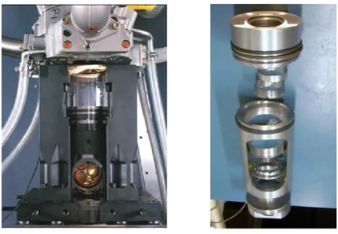
Figure 2.7: A view of the head & optical of the LOTUS SCORE. (Lotus,2013)
Most optical access engine are able to apply these diagnostics however the LOTUS package is able to operate at real engine loads and speeds up to 5000RPM. Another feature available in the SCORE package is AVT (Active Valve Train) which is a hydraulically actuated valve system utilising advanced electronic control to manipulate and thus test and research valve timing and depression effects on combustion.
The system was developed to support research into Low Temperature Combustion, Controlled Auto Ignition and Homogeneous Charge Compression Ignition (HCCI). All of which can be researched using the LOTUS SCORE system.
The RICARDO group offer their own packages of optical research engines, divided into two groups named Hydra & Proteus these research engines are available in a variety of sizes and feature options. The Hydra package is the lighter duty package available in petrol, diesel & alternative fuels with GDI, port injection & diesel DI or IDI. Bore sizes between 65mm & 110mm, the valve train is available in Camless hydraulic valve (HVA) which is similar to LOTUS AVT, variable lift or standard cam actuated to name a few features. Essentially this engine is suitable for typical automotive engine research. The Proteus package is the heavy duty package more aimed at the transport and marine engine research with bore size from 100mm to 150mm and peak pressures of 250bar.
Numerous research facilities including universities utilize the Ricardo engines for their laboratories, Ricardo claim their engines have contributed to 250 research papers in the last forty years. (Ricardo,2013).
What appears to set the Ricardo & Lotus engines apart from University laboratory engine setups are the peripherals and polished finish to the
product. Operational features in general are superior to the typical University setup such as their engines can operate at full loads for research where many other setups need employ techniques such as skip firing to control temperatures. This may be erroneous as a research paper discussing an experiment is obliged to inform the reader of limitations, manufacturers almost never mention them in their marketing media.
2.6 The USQ optical access engine
To put the USQ engine into perspective or at least what has been designed at this stage refer back to table 2.5. The USQ engine is a single cylinder engine like most other engine setups reviewed; utilizing balance shafts to counter the operating inertia forces. As opposed to the slightly less common alternative of running one optical access cylinder in an operational or non-operational multi-cylinder engine arrangement for balance.
The USQ engine will be a bowditch piston type optical access arrangement, an optical bore will be included in the design for expected laser diagnostics. The use of endoscopic probes is unknown at the moment as the head arrangement is yet to be finalised.
Referring below to a flyer image for the Hydra light design marketed by Ricardo Group you can see similarities building between this product and the USQ engine. To get a better idea of this refer to the general arrangement drawing 4111-A001 found in Appendix C.
Figure 2.8: Ricardo Hydra Engine Image (Ricardo, 2013)
At this stage the USQ engine has been designed as an intended petrol engine however to allow flexibility in research down the track the piston, crankshaft & conrod are being designed to operate at higher than likely pressures to allow for the possibility of operation as a diesel engine, hybrid fuels engine etc. This hopefully will allow USQ to research more recent developments in combustion technology such as HCCI (Homogeneous Charge Compression Ignition), Low Temperature Combustion, PCCI (Premixed Charge Compression Ignition) and hopefully more.
2.7 Engine Design
This report is more of a design paper than a research paper however in order to design an optical access engine, research into what and optical access engine is, it’s purpose and features, design pitfalls to avoid and specific mechanical design knowledge need be covered.
So far the literature review has covered the what, why & who of optical research engines but only briefly the how of their design. Most technical papers on the subject are more focused on the results of combustion research using these engines as opposed to detailing the research methodology used to design. It will be the focus of this paper to cover this missing content and provide insight into the design process. To design an engine be it an optical access I.C.E. or a typical I.C.E. research must be performed into the design of various components and the understanding of phenomenon relative to the specific machine.
Below is an abridged list of texts and papers utilized for research into the design of the USQ Optical Access Engine.
• Engine Balancing: Design of Machinery (Norton 2000) & Introduction to Internal Combustion Engines (Stone 1999)
• Mechanical Fatigue: Shigley’s Mechanical Engineering Design (Budynas et al. 2012)
• Solid Mechanics: Roark’s Formulas for Stress & Strail (Young et al. 2012)
• Crankshaft Design: Calculation of Crankshafts for Internal Combustion Engines (Paper) (Germanischer Lloyd, 2012)
• Piston Stresses: Impact of Mechanical Deformation due to Pressure, Mass & Thermal Forces on the In- cylinder Volume Trace in Optical Engines of
Bowditch Design (SAE Paper) (Aronsson, U, 2011)
• Materials: Matweb.com website ; Bohler Uddeholm website; Capral Aluminium Catalogue; Dotmar Plastics website; Glacier Bearings DU catalogue; Heraeus Quartz datasheets, ASME Handbook, CP Carillo general catalogue.
• Small parts: Blackwoods Catalogue; Bearing Services (BSC Catalogue; Unbrako Fasterners Catalogue
• Cylinder Pressures Cylinder Pressure in a Spark Ignition Engine: A Computational Model (Kuo,PS , 1996); Perry’s Chemical Engineers Handbook (2012)
Methodology
This chapter covers the design considerations, procedures, tools & resources for the design of the USQ optical access engine as far the project scope covers. The results of work outlined in this chapter will be covered in the next section: Results/Discussion.
The specific aspects and components covered in this chapter will be,
• Engine Balancing: Theory & Design, Application of Virtual Balancing.
• Crankshaft Design: Cylinder Pressures, Application of Design Paper, FEA
• Conrod Design: Designing for Infinite Life (Fatigue), FEA.
• Bearing Design: Main Bearings, Big-End, Little End
• Piston Design: Design Considerations, Window Strength, FEA
• Various Design: Various Design Considerations not Covered
Overall Considerations
As mentioned in the introduction one of the design constraints for this project is for this engine to be fabricated in a typical engineering workshop, for example but not specifically the USQ fabrication workshop. Throughout this project and particularly during the modelling stage this consideration was one of the foremost factors influencing design decisions.
An example of this is when looking at the geometrical shaped of most parts an experienced tradesperson should be able to see that it can be made from common billet stock material and machined using a manual centre lathe & universal mill. Certain parts will be very much easier if machined in a three axis CNC mill however no major part should require anything more than this.
Chapter
3
Material sizes have been kept to a minimum, the aim being to reduce material and machining costs.
Further to the interest of simplifying the design and solving certain parts issues it was decided at this stage to utilize the head off an existing engine. The head arrangement is probably the most complicated part of an engine and in using an existing head from an engine with a similar sized engine cylinder considerable time, money and design work can be saved.
After extensive research the engine selected was a Mitsubishi 4G93 engine, this engine possesses the same stroke as the original design by Prof. Stone and a bore size only one millimetre larger. By increasing the existing design bore size to the Mitsubishi engine’s a number of parts can utilized; parts such as the oil rings, internal head components, head gaskets, fuel injection system, ignition system to name a few can be used in constructing the engine.
When making further design choices, if a part from the 4G93 is suitable it is not designed. Similarly or when a design decision or assumption needs to be made the Mitsubishi engine weighs considerably in the final outcome. One example of this is the ignition timing.
3.1
Engine Balancing
Due to the reciprocating manner of an internal combustion engine I.C.E. there are large forces at play during operation. These forces increase with respect to engine size (specifically piston or reciprocating mass) and engine RPM. It is important to reduce and counter these forces as much as practicable in order to prevent any adverse effect as a result of their presence.
The methods of dealing with the reciprocating forces in an I.C.E. are mass reduction and balancing. Both have been applied in the design of this engine, with respect to mass reduction the piston and conrod have been designed as light as possible with compromising structural integrity. It is the balancing that shall be the focus of this section.
3.1.1 Balancing Theory
The following sections cover the theory behind determining the inertia forces induced by the slider crank mechanism operating. This leads to how to counter these forces and thus balance the engine.
3.1.1.1 Slider Crank Kinematics
Below in figure 3.1 is the first design revision of the piston, conrod and crankshaft arrangement used in the project engine. It is this arrangement that was used to establish the theoretical model which will be explained here. The following theory for the piston displacement, velocity & acceleration is taken from (Introduction to Internal Combustion Engines 3rd
ED., Richard Stone 1999).
The piston position or distance - X - is given by the equation….
𝑥𝑥= 𝑟𝑟cos𝜃𝜃+𝑙𝑙cos∅ Eq 3.1
Figure: 3.1: Crankshaft, Bowditch Piston & Conrod Arrangement: Dimensioned for Kinematic Analysis
Note that….
𝑟𝑟sin𝜃𝜃 =𝑙𝑙sin∅ Eq 3.2
Remember that….
𝑐𝑐𝑐𝑐𝑐𝑐∅ = √(1− 𝑐𝑐𝑠𝑠𝑠𝑠2∅) Eq 3.3
Using equations 2.2 & 2.3 we can represent the piston position as …..
𝑥𝑥= 𝑟𝑟(𝑐𝑐𝑐𝑐𝑐𝑐𝜃𝜃+ 𝑙𝑙 𝑟𝑟���1− �𝑟𝑟 𝑙𝑙��2𝑐𝑐𝑠𝑠𝑠𝑠2𝜃𝜃�) Eq 3.4
Using the Binomial Theorem to expand the square root term into ….
𝑥𝑥= 𝑟𝑟{𝑐𝑐𝑐𝑐𝑐𝑐𝜃𝜃+ 𝑙𝑙 𝑟𝑟�{1− 1 2(𝑟𝑟 𝑙𝑙⁄ )
2𝑐𝑐𝑠𝑠𝑠𝑠2𝜃𝜃 − 1 8(𝑟𝑟 𝑙𝑙⁄ )
4𝑐𝑐𝑠𝑠𝑠𝑠4𝜃𝜃+⋯. Eq 3.5
The powers of sinθ can be expressed as….
𝑐𝑐𝑠𝑠𝑠𝑠2𝜃𝜃 = 1
2−12𝑐𝑐𝑐𝑐𝑐𝑐2𝜃𝜃
𝑐𝑐𝑠𝑠𝑠𝑠4𝜃𝜃 = 3
8− 12𝑐𝑐𝑐𝑐𝑐𝑐2𝜃𝜃+ 18𝑐𝑐𝑐𝑐𝑐𝑐4𝜃𝜃 Eq 3.6
Substituting Eq3.6 into 3.5 we get….
𝑥𝑥= 𝑟𝑟{𝑐𝑐𝑐𝑐𝑐𝑐𝜃𝜃+ 𝑙𝑙 𝑟𝑟�[1− 1 2�𝑟𝑟 𝑙𝑙��
2
�1
2 −12𝑐𝑐𝑐𝑐𝑐𝑐2𝜃𝜃� − 18�𝑟𝑟 𝑙𝑙��
4
�3
8−12cos 2𝜃𝜃+ 1
8𝑐𝑐𝑐𝑐𝑐𝑐4𝜃𝜃� Eq 3.7
Since the conrod length or “l” must be twice the crank arm length or “r” plus allow clearance for the diameter of the big end bearing, piston skirting or barrel the ratio (r/l)2 is invariably less than 0.1, which means that (r/l)4 is an
acceptable term to neglect.
Therefore an acceptable approximation of the piston position is…
𝑥𝑥 ≈ 𝑟𝑟{𝑐𝑐𝑐𝑐𝑐𝑐𝜃𝜃+ 𝑙𝑙 𝑟𝑟��1−1 2�𝑟𝑟 𝑙𝑙��
2
�1
2−12𝑐𝑐𝑐𝑐𝑐𝑐2𝜃𝜃��} Eq 3.8
Differentiating Eq 3.8 once with respect to time yields piston velocity twice yields acceleration given in the equations below…
𝑥𝑥̇= −𝑟𝑟𝜔𝜔(𝑐𝑐𝑠𝑠𝑠𝑠𝜃𝜃+ 1
2𝑟𝑟� 𝑐𝑐𝑠𝑠𝑠𝑠𝑙𝑙 2𝜃𝜃) Eq 3.9
𝑥𝑥̈= −𝑟𝑟𝜔𝜔2(𝑐𝑐𝑐𝑐𝑐𝑐𝜃𝜃+ 𝑟𝑟
𝑙𝑙
� 𝑐𝑐𝑐𝑐𝑐𝑐2𝜃𝜃) Eq 3.10
Using the equation for acceleration the axial force developed in the engine due to the reciprocating mass can be expressed as…
𝐹𝐹𝐹𝐹𝑟𝑟𝑟𝑟≈ 𝑚𝑚𝑟𝑟𝑟𝑟𝑟𝑟𝜔𝜔2(𝑐𝑐𝑐𝑐𝑐𝑐𝜃𝜃+ 𝑟𝑟� 𝑐𝑐𝑐𝑐𝑐𝑐𝑙𝑙 2𝜃𝜃) Eq 3.11
Where 𝐹𝐹𝐹𝐹𝑟𝑟𝑟𝑟 = vertical force due to the reciprocating mass
𝑚𝑚𝑟𝑟𝑟𝑟 = equivalent reciprocating mass
𝜔𝜔 = angular velocity, dθ/dt
𝑟𝑟 = crankshaft throw
𝑙𝑙 = conrod length (bearing centres)
𝑐𝑐𝑐𝑐𝑐𝑐𝜃𝜃 = primary term
𝑐𝑐𝑐𝑐𝑐𝑐2𝜃𝜃 = secondary term
𝜃𝜃 = crank angle in degrees (0° = TDC)
Studying equation 3.11 you can see there is a primary force varying in amplitude with crankshaft rotation with the maximum amplitude governed by the reciprocating mass & angular velocity. This can be graphically expressed in a simple harmonic wave form with the maximum corresponding to crank angles of 0 & 180 degrees. (Refer figure 2.3)
There is a secondary force present corresponding to the second term in equation 3.11, this force varies in amplitude at twice the speed of the crankshaft and hence its maximum values correspond to the crank angles 0, 90, 180, & 270 degrees. (Remember the direction of the forces will change, this is denoted by a change in sign).
3.1.1.2 Equivalent Masses
To help clarify equation 3.11 and the graph below, the reciprocating masses needs to be clarified. “When calculating the engine balance, the connecting rod is treated as two masses concentrated at the centre of the big end and the centre of the little end.” (Stone, 1999, p447).
Figure 3.2 below is the conrod taken from the first design revision, using this drawing it can be seen how the conrod can be described as two masses about a centre of gravity.
Figure: 3.2: The first connecting rod revision & its equivalent model.
The following theory is also taken from (Introduction to Internal Combustion Engines 3rd ED., Richard Stone 1999).
For equivalence…
𝑚𝑚(𝑐𝑐𝑐𝑐𝑐𝑐𝑟𝑟𝑐𝑐𝑐𝑐) =𝑚𝑚1+ 𝑚𝑚2 Eq 3.12
𝑚𝑚1𝑟𝑟1 = 𝑚𝑚2𝑟𝑟2 Eq 3.13
The mass m2 can be considered as part of the reciprocating mass giving
mrm as the sum of the piston mass and m2. (Stone, 1999).
𝑚𝑚𝑟𝑟𝑟𝑟 =𝑚𝑚𝑝𝑝+𝑚𝑚2 Eq 3.14
Where mp = Piston mass
m2 = Little end bearing mass
These equations and resulting equivalent masses when applied to the conrod allow the allocation of mass to the reciprocating mass component and thus equation 3.11. The remaining mass forms part of the crankshaft model and requires balancing through the crankshaft design.
Taking Eq 3.11, 3.14 and inputting the final masses for the piston & conrod along with the engine speed we get the following plot of the engine shaking forces (Vertical) in Newtons (N) with respect to crank angle (θ). In red is the total reciprocating force produced by the engine. In blue and black are the primary and secondary forces that make up the total force. The magnitude of the plotted forces varies with engine speed and should be ignored at this stage, what is important is the pitch and phase.
The plot below contains three traces where,
𝐹𝐹𝐹𝐹𝑟𝑟𝑝𝑝 =𝑃𝑃𝑟𝑟𝑠𝑠𝑚𝑚𝑃𝑃𝑟𝑟𝐹𝐹𝑅𝑅𝑅𝑅𝑐𝑐𝑠𝑠𝑅𝑅𝑟𝑟𝑐𝑐𝑐𝑐𝑃𝑃𝑅𝑅𝑠𝑠𝑠𝑠𝑅𝑅𝐹𝐹𝑐𝑐𝑟𝑟𝑐𝑐𝑅𝑅𝑐𝑐=𝑚𝑚𝑟𝑟𝑟𝑟𝑟𝑟𝜔𝜔2𝑐𝑐𝑐𝑐𝑐𝑐𝜃𝜃
𝐹𝐹𝐹𝐹𝑟𝑟𝑟𝑟 =𝑆𝑆𝑅𝑅𝑐𝑐𝑐𝑐𝑠𝑠𝑆𝑆𝑃𝑃𝑟𝑟𝐹𝐹𝑅𝑅𝑅𝑅𝑐𝑐𝑠𝑠𝑅𝑅𝑟𝑟𝑐𝑐𝑐𝑐𝑃𝑃𝑅𝑅𝑠𝑠𝑠𝑠𝑅𝑅𝐹𝐹𝑐𝑐𝑟𝑟𝑐𝑐𝑅𝑅𝑐𝑐= 𝑚𝑚𝑟𝑟𝑟𝑟𝑟𝑟𝜔𝜔2 𝑟𝑟� 𝑐𝑐𝑐𝑐𝑐𝑐𝑙𝑙 2𝜃𝜃
𝐹𝐹𝐹𝐹𝑟𝑟𝑟𝑟= 𝑇𝑇𝑐𝑐𝑅𝑅𝑃𝑃𝑙𝑙𝑅𝑅𝑅𝑅𝑐𝑐𝑠𝑠𝑅𝑅𝑟𝑟𝑐𝑐𝑐𝑐𝑃𝑃𝑅𝑅𝑠𝑠𝑠𝑠𝑅𝑅𝐹𝐹𝑐𝑐𝑟𝑟𝑐𝑐𝑅𝑅𝑐𝑐= 𝐹𝐹𝐹𝐹𝑟𝑟𝑝𝑝+𝐹𝐹𝐹𝐹𝑟𝑟𝑟𝑟 = 𝐸𝐸𝐸𝐸 3.11
Figure: 3.3: Representation of Reciprocating Forces Inside the Optical Access Engine. Note: Maximum forces occur at TDC (0°,360°,720°) & BDC (180°,540°)
It is important to note from the above equations and figure 3.3 that the total shaking or reciprocating forces are the sum of two sets of oscillating forces. It is these forces also known as shaking forces that are the focus of the balancing and will be discussed further in “Slider Crank Kinematics & Engine Balancing”.
3.1.1.3 Shaking Torque
Another influence on the engines stability is the presence of shaking torque commonly known as inertia torque, inertia torque results from the action of the inertia forces at a moment arm. These arise due to the lateral component of the force driving the little end bearing component of the conrod plus the piston along its path by the distance of the little end bearing from the crankshaft centre. For a clearer picture refer to figure 3.4below.
Figure: 3.4: Representation of Shaking Torque
Shaking torque can be represented with respect to crank angle as opposed to conrod as described in figure 3.4 above by the following equation (Norton,2000) ,
𝑇𝑇𝑐𝑐 = 12𝑚𝑚𝑏𝑏𝑟𝑟2𝜔𝜔2[2𝑙𝑙𝑟𝑟 𝑐𝑐𝑠𝑠𝑠𝑠𝜃𝜃 − 𝑐𝑐𝑠𝑠𝑠𝑠2𝜃𝜃 −3𝑟𝑟2𝑙𝑙𝑐𝑐𝑠𝑠𝑠𝑠3𝜃𝜃] Eq 3.15
Where Ts = Shaking torque
Shaking torque has an average value of zero and thus contributes nothing to the net driving torque. (Norton,2000). Shaking torque is can be counteracted in a multicylinder engine however is not practicable to counter in a single cylinder engine. To reduce the shaking torque without affecting engine function the reciprocating mass must be reduced.
3.1.2 Slider Crank Kinematics & Engine Balance
Now that the shaking forces produced by the engine have been identified and broken down into components and magnitudes how to counter these forces will be discussed.
3.1.2.1 Shaking Forces
In a single cylinder engine as is the case here, the primary forces can be mostly cancelled out using a weighted crankshaft. This weight is known as the “bob weight” and is the common method of improving the balance of a single cylinder engine. The is weight is intended to provide a 180° out of phase sinusoidal varying force of mostly the same magnitude as the primary reciprocating force, it also balances the rotating force of the big end bearing & lower conrod (m1).
However the bob weight does not counter the secondary forces of the reciprocating mass. What is required to counter the secondary forces is the introduction of another harmonic force at the same frequency but at a phase angle of 180° to the engine’s second order forces. The amplitude must match the secondary forces so as to perfectly counter and thus eliminate the engine shaking produced by the second order forces.
Although this sounds complicated it is quite simple, by introducing two opposite rotating balance shafts turning at twice the engine speed and timed at 180° to the engine the secondary forces, they both cancel out. (Stone 1999). Figure 3.5 below gives a simplified demonstration of this concept.
Figure: 3.5 Representation of Rotating Counter Balance Shafts (Stone,1999)
By employing a bob-weight and counter balance shafts the vertical shaking forces can be counter-acted and thus reduced to acceptable levels. Another advantage of employing bob-weights is the forces are reduced at the source and thus smaller crankshaft bearing may be utilised. However by employing a bob-weight you create an alternating force at 90° to the travel of the piston the magnitude of which is calculated using the equation below.
𝐹𝐹𝑥𝑥𝑏𝑏𝑟𝑟 = 𝑚𝑚𝑏𝑏𝑟𝑟𝑏𝑏𝜔𝜔2cos (𝜃𝜃+ 90) Eq 3.16
Where 𝐹𝐹𝑥𝑥𝑏𝑏𝑟𝑟 = force at 90° to the piston axis due to the bobweight
𝑚𝑚𝑏𝑏 = effective bob-weight mass
𝜔𝜔 = angular velocity (dθ/dt) or engine speed
𝑟𝑟𝑏𝑏 = radius of the bob-weight COG for crankshaft centre
𝜃𝜃 = crank angle (0° = TDC)
Giving a total alternating force at 90° to the piston travel of,
∑ 𝐹𝐹𝑥𝑥 = 𝜔𝜔2 sin𝜃𝜃 [𝑚𝑚
𝑏𝑏𝑟𝑟𝑏𝑏− 𝑚𝑚𝑏𝑏𝑏𝑏𝑟𝑟] Eq 3.17
Where sin𝜃𝜃 = cos (𝜃𝜃+ 90)
𝑚𝑚𝑏𝑏𝑏𝑏 = mass of the crankshaft & conrod big-end bearing
This is a useful trade off as usually the direction of the shaking forces is not of concern simply the magnitude (Norton,2001). Norton was considering the practicalities of the engine design ie: cost and complexity when he considered it in acceptable trade off. Norton also did not use the twin counterbalance shafts in his single cylinder end balancing analysis, similarly engine manufactures by employing only a bob-weight to balance their engines.
In the USQ optical engine design the additional cost of employing the counterbalance shafts to eliminate shaking forces is worth the investment, especially considering the potential improvements. It is actually worth balancing the crankshaft so that there are no alternating forces at 90° to the piston travel and employing four sets of counterbalance shafts. Two shafts in order to balance the primary forces and two shafts to balance the secondary forces. As they are in equal and opposite rotation only vertical forces are produced and in opposition to the engine shaking forces.
This design is demonstrated in the next section, please refer to figure 3.6. It is unclear if Prof. Stone intended for the crankshaft to be statically balanced and have the balance shafts do all of the work countering the reciprocating mass. However in the interest of the best possible final result this is the approach taken. By simply increasing the mass of the bolt on bob-weights and reducing the primary balance bob-weights more of the balancing workload can be performed at the crank. This adjustable approach was chosen to give operational flexibility to the end user.
3.1.2.2 Applying Balancing Theory to the Stone Engine Design
In the engine design by (Stone et al.) provided to USQ there was the addition of four balance shafts, two rotating at engine speed & two at twice the engine speed. As discussed in the previous section this is to counter the primary and secondary forces by means of equal magnitude and phase opposition.
Referring to figure 3.3 the trace of Fyrm which represents the total shaking
force as the sum of the primary shaking forces Fyrp and the secondary
shaking forces Fyrs it can be seen by inspection that if the engine design was
to provide equal and opposite forces then the total shaking forces would be reduced to zero. It is by this concept that our engine balance and thus the elimination of shaking forces (not torques) is realized.
Figure 3.6 below isa simplified drawing of the piston, crankshaft and balance shaft cluster in the engine design. These parts can be seen along with the
rotational and directional orientations of the moving parts. Using the following equations and assumptions we can realize a balanced system with respect to shaking forces in all directions.
𝐹𝐹𝐹𝐹𝑝𝑝𝑐𝑐𝑏𝑏 =𝑚𝑚𝑝𝑝𝑐𝑐𝑏𝑏∙ 𝜔𝜔2∙ 𝑟𝑟𝑝𝑝𝑐𝑐𝑏𝑏 Eq 3.18
𝐹𝐹𝐹𝐹𝑟𝑟𝑐𝑐𝑏𝑏 = 𝑚𝑚𝑟𝑟𝑐𝑐𝑏𝑏∙(2𝜔𝜔)2∙ 𝑟𝑟𝑟𝑟𝑐𝑐𝑏𝑏 Eq 3.19
𝑚𝑚𝑏𝑏𝑟𝑟𝑏𝑏− 𝑚𝑚𝑏𝑏𝑏𝑏𝑟𝑟= 0 Eq 3.20
Where Fypcb = Primary counter balance shaft force (vertical)
Fxscb = Secondary counter balance shaft force (vertical)
mp = Primary counter balance mass (combined)
ms = Secondary counter balance mass (combined)
Assuming a perfect statically balanced crankshaft arrangement is achieved including the conrod big-end bearing mass thus achieving by design and test equation 3.20. The following equations can be realized by application of the correct counter balance weights and bob weights. It is this application that is the work of balancing the engine, the purpose of this section and one of the main design targets.
∑ 𝐹𝐹𝐹𝐹= 𝐹𝐹𝐹𝐹𝑟𝑟𝑟𝑟+ 𝐹𝐹𝐹𝐹𝑝𝑝𝑐𝑐𝑏𝑏+ 𝐹𝐹𝐹𝐹𝑟𝑟𝑐𝑐𝑏𝑏 = 0 Eq 3.21
∑ 𝐹𝐹𝑥𝑥 = 𝜔𝜔2 sin𝜃𝜃 [𝑚𝑚
𝑏𝑏𝑟𝑟𝑏𝑏− 𝑚𝑚𝑏𝑏𝑏𝑏𝑟𝑟] = 0 Eq 3.22
The application of these into a theoretical model along with the results shall be discussed further in the next chapter. To view the model please refer to Section 2.0 of Appendix B where a printout of the equations used in the mathematical software is presented. Please note the nomenclature is not exactly the same as that used here however it is close and understandable. The forces derived from Eq 3.11, 3.18 & 3.19 above are also useful with respect to determining bearing loads on both the main bearings and the
balance shaft bearings, the calculations used for determining bearing life and capacity can be found in later sections of this chapter as well as Section 4.2 of Appendix B.
Figure: 3.6: Crank & Balance Shaft Arrangement for this Project (Revision A)
The application of the theory discussed is carried out frequently in the design and component verification of this engine. Situations such determining crankshaft stresses, conrod stresses, wrist pin bending as well as the bearings mentioned above are a few examples of these. Careful calculation and application of this theory will play an essential part in the successful design of our optical access engine.
3.1.3 Virtual Balancing
To give confidence to the design by verifying the theory given in the earlier sections the engine model will be been turned over using mechanical virtual simulation software. The software package used specifically is Autodesk Mechanical Simulator which is part of the Inventor design suite used to solid model the engine and create the drawings.
Although much of the process of setting up the simulation is automated when the same software is used to create the solid model as run the simulation, it is still i