Predictive Resource Allocation in the LTE Uplink
for Event Based M2M Applications
Jason Brown and Jamil Y Khan
School of Electrical Engineering and Computer Science The University of Newcastle
Callaghan, NSW 2308, AUSTRALIA Email: {jbrown1, jamil.khan}@newcastle.edu.au
Abstract— For certain event based M2M applications, it is possible to predict when devices will or may need to send data on the LTE uplink. For example, in a wireless sensor network, the fact that one sensor has triggered may increase the probability that other sensors in the vicinity may also trigger in quick succession. The existing reactive LTE uplink access protocol, in which a device with pending data sends a scheduling request to the eNodeB at its next scheduled opportunity, and the eNodeB responds with an uplink grant, can lead to high latencies. This is particularly the case when the system utilizes a high scheduling request period (of up to 80ms) to support a large number of devices in a cell, which is characteristic of M2M deployments. In this paper, we introduce, analyze and simulate a new predictive/proactive resource allocation scheme for the LTE uplink for use with event based M2M applications. In this scheme, when one device in a group sends a scheduling request, the eNodeB identifies neighbor devices in the same group which may benefit from a predictive resource allocation in lieu of waiting for those neighbors to send a scheduling request at their next scheduled opportunity. We demonstrate how the minimum uplink latency can be reduced from 6ms to 5ms and how the mean uplink latency can be reduced by greater than 50% (in certain scenarios) using this method.
Index Terms— LTE, M2M, predictive scheduling, proactive scheduling, OPNET.
I.INTRODUCTION
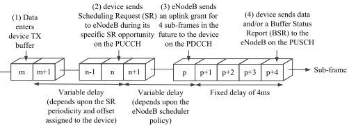
Although the 3GPP Long Term Evolution (LTE) uplink is designed to support a data plane latency of less than 10ms [1], typical latencies can be significantly higher depending upon the system configuration, load, packet size and channel conditions [2]. Consider the uplink latency components depicted in Fig. 1 for a device in the RRC_CONNECTED state [3] (i.e. the high energy device state of LTE). In particular, a device sends a Scheduling Request (SR) message [4] to indicate to the LTE network that it needs to be scheduled for uplink data transmission. The device must wait for its individual pre-assigned offset sub-frame within an SR period, TSR, to send its SR [5]. Therefore the waiting time for a device to send its SR is a continuous random variable with a uniform distribution over the interval [0, TSR). TSR is a system configuration variable with allowed values 5, 10, 20, 40 and 80ms [5] with higher values usually employed to support a large number of devices as in an M2M deployment. With TSR = 80ms, the mean delay from this
component alone is (0+80)/2 = 40ms which is far higher than the design goal of 10ms.
[image:1.612.317.568.414.504.2]As illustrated in Fig. 1, after receiving the SR, the eNodeB schedules the device for uplink data transmission. This is a reactive model as the eNodeB only allocates uplink resources in response to the receipt of an SR indicating that a device has pending uplink data. In a highly loaded system, the scheduling may be subject to a delay. When the device receives its uplink scheduling grant, the grant applies to a fixed offset of 4 sub-frames or 4ms in the future [5]. Consequently, the absolute minimum uplink latency is 6ms which assumes that, by chance, the SR can be sent in the very next sub-frame after the data packet enters the device buffer.
Fig. 1: Uplink Latency Components in LTE
There is little opportunity to reduce the uplink latency for traditional voice and data devices which typically act independently of other devices in the vicinity. However, for a group of related M2M devices such as sensors in a Wireless Sensor Network (WSN) in which the fact that one sensor has triggered may increase the probability that other sensors in the vicinity may also trigger in quick succession, we can exploit the correlated traffic patterns between related devices of the group to reduce latency. In particular, when one device in the group sends data, and the time to the next SR opportunity for a neighbor device in the same group is, by chance, greater than some threshold, we consider how the eNodeB can proactively use predictive resource allocation to grant this neighbor device resources to send its packet(s) ahead of its regular SR opportunity, thereby reducing latency. We demonstrate how the
p p+1 m m+1
(1) Data enters device TX
buffer
n-1 n n+1 p+2 p+3 p+4 (2) device sends
Scheduling Request (SR) to eNodeB during its specific SR opportunity
on the PUCCH
(3) eNodeB sends an uplink grant for 4 sub-frames in the future to the device on the PDCCH
(4) device sends data and/or a Buffer Status Report (BSR) to the eNodeB on the PUSCH
Fixed delay of 4ms Variable delay
(depends upon the SR periodicity and offset assigned to the device)
Variable delay (depends upon the eNodeB scheduler
policy)
Sub-frame PUCCH Physical Uplink Control Channel
minimum latency can be reduced from 6ms to 5ms and how the mean latency can be reduced by greater than 50% using this method. Of course, there is a risk with unsolicited predictive resource allocation that resources will be assigned to a device before it has a packet to send, and therefore, to some extent, there is a compromise between latency reduction and resource wastage. The requirements of the application dictate the aggressiveness of the predictive resource allocation in an actual deployment.
It might be considered unlikely that all M2M devices in a group would remain in the RRC_CONNECTED state for an extended period of time. However, there are application scenarios where this can be justified, for example in a Smart Grid where devices are externally powered and latency is a critical factor for control and protection. Furthermore, even when devices normally reside in the RRC_IDLE state, there may be occasions where they are proactively migrated to the RRC_CONNECTED state in anticipation of some event.
There is some related work in the literature. In [6], a predictive scheduling algorithm for uplink traffic in IEEE 802.16 networks is described which aims to reduce latency for the real time polling service (rtPS) based upon analysis of the bandwidth request queues at the base station, although this work does not exploit the correlated traffic patterns associated with some M2M applications. In [7-8], the authors define proactive/predictive resource allocation for wireless networks at the single user level in order to afford delay and capacity gains. In contrast, our work addresses predictive resource allocation at the multi-user/device single group level.
II.PREDICTIVE UPLINK RESOURCE ALLOCATION
A.Description
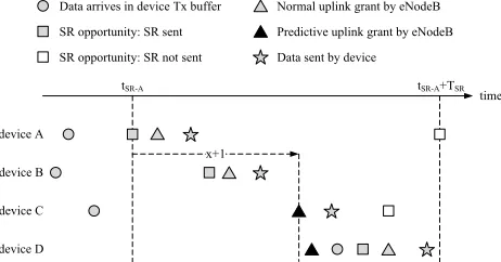
[image:2.612.55.286.580.701.2]Fig. 2 illustrates the concept of predictive uplink resource allocation. Devices A, B, C and D are members of the same group (e.g. sensors in a WSN). Device A is the first to send an SR based upon some event, although it is not necessarily the first device to compose a data packet for transmission based upon the event (that title belongs to device B in the Fig. 2). Devices B, C and D are neighbors of device A based upon some metric (usually distance between devices) and must be labelled as such in the eNodeB in order to facilitate predictive resource allocation since predictions must be targeted at specific devices which are likely to have pending data in order to minimise resource wastage.
Fig. 2: Predictive Uplink Resource Allocation Concept
We assume throughout that although each device has a periodic SR opportunity every TSR seconds, the offset of that SR opportunity within the period is assigned randomly by the eNodeB. In particular, we assume the eNodeB does not intentionally assign similar offsets to devices which are neighbors in an attempt to allow those devices to send SRs in quick succession when an event occurs. Such a design will in general afford no advantage (and can be counter-productive) unless the speed and direction of the event propagation are known in advance. In the example of Fig. 2, we see that the SR opportunities of the four devices are spread across the SR period without any intentional ordering or staggering even though devices B, C and D are neighbors of device A.
The eNodeB uses the normal uplink resource allocation for device A since it is the first device to indicate that uplink data is pending. However, once the eNodeB has received the SR from device A, it considers which of its neighbors should be subject to predictive resource allocation. This is based upon the interval to the next SR opportunity for each neighbor. If this interval is greater than a certain threshold of (x+1) subframes, where x∈ {0, 1, 2 … TSR-3}, the eNodeB predictively allocates resources for the neighbor ahead of the regular SR opportunity for that neighbor in order to reduce latency. The predictive resource allocation is such that it will not occur earlier than (x+1) sub-frames following receipt of the SR from device A.
The criterion for predictive resource allocation is based upon (x+1) rather than x to prevent a predictive uplink grant being sent by the eNodeB to a device in the same subframe as the device is sending an SR to the eNodeB (note this can only possibly occur in FDD mode which supports simultaneous uplink/downlink operation). For example, for x=0, the (x+1) criterion means that only neighbor devices with an SR opportunity greater than 1 sub-frame (i.e. 2 sub-frames or more) in the future can be considered for predictive resource allocation, whereas the predictive resource allocation made by the eNodeB itself can occur in (x+1) = 1 sub-frame in the future.
Referring to Fig. 2, for neighbor device B, the next SR opportunity occurs less than (x+1) subframes after the SR was received from device A; therefore the eNodeB does not issue a predictive uplink grant and the uplink resource allocation occurs normally.
For neighbor device C, the next SR opportunity occurs more than (x+1) subframes after the SR was received from device A; therefore the eNodeB issues a predictive uplink grant for device C, in this case exactly (x+1) subframes after the SR was received from device A. There is pending uplink data for device C at the time the predictive resource allocation is made, and this data is transmitted a fixed interval of 4 subframes (4ms) after the predictive uplink grant is received. Therefore, for device C, the predictive resource allocation is successful and the device does not transmit an SR at its next SR opportunity (since there is no data to transmit at the time of this opportunity). Note that because the predictive resource allocation is achieved without sending an SR, the minimum possible uplink latency is reduced from 6ms to 5ms.
time tSR-A tSR-A+TSR
x+1 device A
device B device C device D
Data arrives in device Tx buffer SR opportunity: SR sent SR opportunity: SR not sent
For neighbor device D, the next SR opportunity occurs more than (x+1) subframes after the SR was received from device A; therefore the eNodeB issues a predictive uplink grant for device D, in this case at more than (x+1) subframes after the SR was received from device A (for example due to scheduling congestion). There is no pending uplink data for device D at the time the predictive resource allocation is made, and therefore the predictive resource allocation is unsuccessful/wasted. Instead device D sends an SR at its next available SR opportunity and the uplink resource allocation follows the normal path. It should be noted that there is an alternative in this case in which device D sends some status information in response to the predictive resource allocation which it would not otherwise have done in order to avoid complete resource wastage, but this is not a possibility we consider further in this paper.
Expanding further on the case of device D, we note that as any uplink allocation in LTE (whether predictive or normal) implies that the target device sends data a fixed interval of 4ms in the future after receiving the grant, there is the possibility that a high performance device may be able to send a data packet which arrives in its transmit buffer up to 4ms after the predictive uplink grant is received from the eNodeB. We do not consider such high performance devices in this paper. The rule we follow is that, in order for a device to send a data packet as part of a predictive resource allocation, the data packet must already be present in the device transmit buffer before the predictive uplink grant is received from the eNodeB.
One issue with predictive uplink resource allocation is that the eNodeB has no indication about the priority or volume of data that a target device may need to send. However, this is in fact exactly the same conundrum faced by the eNodeB with normal uplink resource allocation because the SR is a flag to indicate that a device has data to send; it does not include any indication about priority or volume of data. Information about priority and volume is only available to the eNodeB after the device transmits a Buffer Status Report (BSR) in the initial uplink grant. Consequently the eNodeB must make a default resource allocation in both schemes. We will assume that each device in the group sends data packets with the same size and that the size is sufficiently small to be accommodated in the default resource allocation irrespective of the channel and modulation coding scheme employed. This is reasonable for many M2M groups of devices.
Devices B and D send SRs that can be used by the eNodeB as the basis of further predictive resource allocations for the neighbors of those devices. Device C does not send an SR as it transfers its packet via a successful predictive resource allocation; in this case, the data packet received as part of the predictive resource allocation can be used by the eNodeB to trigger further predictive resource allocations.
If a device has sent an SR or been scheduled for predictive resource allocation recently (i.e. as determined by a configurable timer), it is not eligible for a predictive resource allocation. This prevents a circular flood of predictive resource allocations in which, for example, device A sends an SR which triggers a predictive resource allocation on device C, and the
packet transferred as part of the predictive resource allocation on device C triggers a predictive resource allocation on device A.
Note that we do not assume anything about the speed, direction or uniformity of the event propagation that results in devices sending data packets in a correlated manner. If the characteristics of the event propagation are known or can be calculated in real time by the eNodeB, it is possible that the eNodeB can make predictive resource allocations based upon the event propagation characteristics and the location of the devices. This aspect is not considered in this paper. The type of predictive resource allocation considered in this paper aims to reduce latency based only upon knowledge of the neighborhood and the time to the next SR opportunity of each device in the group.
One final observation relates to Discontinuous Reception (DRX) [4] which is an important energy saving feature for devices in the RRC_CONNECTED state. When DRX is active, a device may be asleep at the time the eNodeB wishes to send it a predictive uplink grant, in which case the eNodeB would need to wait until the next scheduled waking time for the device. This does complicate the predictive resource allocation scheme, but because the eNodeB is aware of the sleep schedule of each device, it can compensate to some extent e.g. by bringing forward a predictive resource allocation to occur just before a device falls asleep. In addition, the DRX parameters can be optimised to facilitate effective predictive resource allocation. This is not a topic we consider in this paper, but it is an important area for future research.
B.Algorithm
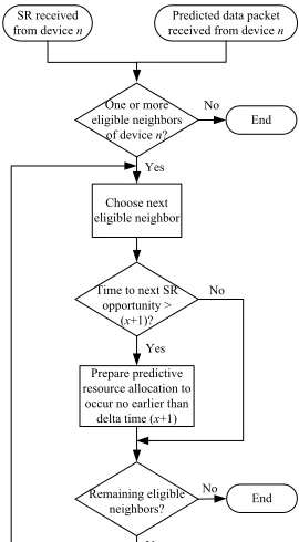
Fig. 3 summarizes the eNodeB predictive uplink resource allocation algorithm introduced in the previous section.
Fig. 3: Predictive Uplink Resource Allocation Algorithm
SR received from device n
Predicted data packet received from device n
One or more eligible neighbors
of device n?
End
Choose next eligible neighbor Time to next SR opportunity >
(x+1)? No Yes
Prepare predictive resource allocation to
occur no earlier than delta time (x+1)
Remaining eligible
neighbors? End No
No Yes
[image:3.612.373.508.442.687.2]One aspect of this algorithm is that each device is only afforded zero or one predictive resource allocations in response to some propagating event. If a predictive resource allocation is unsuccessful because a device does not have a pending uplink data packet when the predictive uplink grant arrives, the eNodeB will not attempt further predictive resource allocations for this device for the current event. This is the case even if there is still a significant interval before the next SR opportunity for the device. Clearly the algorithm can be improved by scheduling further predictive resource allocations (at the expense of more resource usage) in this situation, but we do not consider this aspect further in this paper.
C.3GPP Standards Impact
The predictive uplink resource allocation scheme outlined for LTE in this paper primarily impacts the internal functionality of the eNodeB. In theory, existing devices in the RRC_CONNECTED state should be able to accept and correctly act upon a predicted/unsolicited uplink resource allocation without first sending an SR. Therefore it is not certain that any modifications to the 3GPP LTE standards are required to support this scheme. However, in order to guarantee interoperability, it would be wise to explicitly state in the standards that devices are expected to process predicted/unsolicited uplink resource allocations without first sending an SR.
III.SIMULATION
A.Simulation Model
We employ an OPNET simulation to characterize the eNodeB predictive uplink resource allocation algorithm as a function of the parameter x.
As far as the M2M group application is concerned, we make use of an abstract model in which a set of LTE enabled sensors are equally spaced along a line. We consider a cascading alarm or fault propagation scenario in which a point along the line is selected at random, and a disturbance emanates bi-directionally from the selected point such that the disturbance takes time τ to travel between adjacent sensors as illustrated in Fig. 4. When the disturbance reaches a sensor, that sensor sends an alarm to a server either via the normal or predictive uplink resource allocation schemes.
Fig. 4: Cascading Alarm Simulation Model
This is a simple model in which each sensor has 2 immediate neighbors for predictive resource allocation purposes, apart from the two sensors at either end of the line which possess just 1 immediate neighbor. In addition, the
disturbance travels at a fixed speed between equally spaced sensors. However, the predictive resource allocation algorithm can be applied to much more complicated application models in which devices have a variable number of neighbors which are not equally spaced.
B.Simulation Parameters
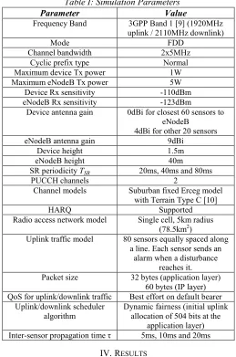
[image:4.612.307.566.159.550.2]Table I lists the parameters employed in the OPNET simulations.
Table I: Simulation Parameters
Parameter Value
Frequency Band 3GPP Band 1 [9] (1920MHz uplink / 2110MHz downlink)
Mode FDD
Channel bandwidth 2x5MHz Cyclic prefix type Normal Maximum device Tx power 1W Maximum eNodeB Tx power 5W
Device Rx sensitivity -110dBm eNodeB Rx sensitivity -123dBm
Device antenna gain 0dBi for closest 60 sensors to eNodeB
4dBi for other 20 sensors eNodeB antenna gain 9dBi
Device height 1.5m
eNodeB height 40m
SR periodicity TSR 20ms, 40ms and 80ms
PUCCH channels 2
Channel models Suburban fixed Erceg model with Terrain Type C [10]
HARQ Supported
Radio access network model Single cell, 5km radius (78.5km2)
Uplink traffic model 80 sensors equally spaced along a line. Each sensor sends an
alarm when a disturbance reaches it. Packet size 32 bytes (application layer)
60 bytes (IP layer) QoS for uplink/downlink traffic Best effort on default bearer
Uplink/downlink scheduler algorithm
Dynamic fairness (initial uplink allocation of 504 bits at the
application layer) Inter-sensor propagation time τ 5ms, 10ms and 20ms
[image:4.612.47.296.555.634.2]IV.RESULTS
Fig. 5 illustrates the mean uplink delay as a function of the predictive resource allocation parameter x for an inter-sensor propagation time τ = 10ms and three values of SR periodicity,
TSR = 20ms, 40ms and 80ms, which are the most appropriate values when considering a large number of devices per cell as is characteristic of M2M applications. Fig. 6 illustrates the proportion of sensors for which a successful prediction is made for the same parameters.
Table II compares the expected mean uplink delay when no predictive resource allocation is in use (assuming no HARQ re-transmissions) by reference to Fig. 1 with minimum and maximum simulated mean uplink delay values for predictive resource allocation extracted from Fig. 5. It can be seen that the mean uplink delay for predictive resource allocation tends to
n n+1
n-1 n+2
τ ρτ (1-ρ)τ τ
X
Origin of disturbance Inter-sensor propagation time: τ 0 ≤ ρ ≤ 1
the expected value for no predictive resource allocation as x
[image:5.612.40.299.169.317.2]increases. The slight difference is due to the fact that HARQ re-transmissions are supported in the simulations and these increase the mean uplink delay. Of course, as x increases and approaches TSR, the number of predictive resource allocations decreases toward zero; in effect, predictive resource allocation is not taking place and therefore we expect the mean uplink delay values to converge to the expected values when no predictive resource allocation is in use.
Fig. 5: Mean Uplink Delay as a Function of Predictive Resource Allocation Parameter x for an Inter-sensor
[image:5.612.43.298.363.520.2]Propagation Time τ = 10ms
Fig. 6: Proportion of Sensors for Which a Successful Prediction is Made as a Function of Predictive Resource Allocation Parameter x for an Inter-sensor Propagation Time
τ = 10ms
Table II: Comparison of Mean Uplink Delay Values
TSR (ms)
Expected Delay for No Predictive Allocation
(ms)
Simulated Delay for Predictive Allocation (ms)
Minimum Maximum
20 6+(0+20)/2 = 16 13.1 (x=4) 16.4 40 6+(0+40)/2 = 26 15.9 (x=6) 26.3 80 6+(0+80)/2 = 46 19.8 (x=6) 46.6
Fig. 5, Fig. 6 and Table II demonstrate clearly that predictive resource allocation is most effective for larger values of TSR. For example, for TSR = 80ms, the minimum mean uplink delay is approximately 19.8ms (when x = 6ms) compared to
46ms when predictive resource allocation is not in use (i.e. a reduction of over 50%). This relationship is to be expected because as TSR increases, there is a greater probability that the time to the next SR opportunity will be greater than (x+1) and there is greater scope for very large reductions of delay for individual sensors for which the time to the next SR opportunity is approaching TSR when a neighbor event occurs.
There is a certain value of x in the range 4-6ms that minimises mean uplink delay in Fig. 5 and maximizes the proportion of sensors for which a successful predictive allocation is made in Fig. 6. As we will illustrate later, this value of x is a function of the inter-sensor propagation time τ. It is not surprising that the optimum value of x should be an intermediate value in general. When x is small e.g. x = 0, there will be a large number of predictive allocations since there will be a high probability that the time to the next SR opportunity will be greater than (x+1), but some of these predictions will ultimately be unsuccessful because the predictive resource allocation is being made at time (x+1) = 1ms before the disturbance has reached the target sensor. When x is large e.g. as x approaches TSR, there will be a small number of predictive allocations since there will be a low probability that the time to the next SR opportunity will be greater than (x+1), but most if not all of these will ultimately be successful because the predictive resource allocation is being made at time (x+1) after the disturbance has reached the target sensor. A certain intermediate value of x therefore produces the minimum value of mean uplink delay, and this value of x will clearly depend upon the inter-sensor propagation time τ since this dictates how quickly a disturbance reaches a neighbor and therefore how likely it is that a predictive resource allocation made at a given time will be successful.
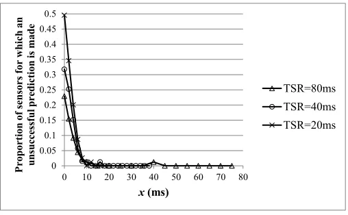
Fig. 7 illustrates the proportion of sensors for which an unsuccessful prediction is made for the same parameters as Fig. 5 and Fig. 6.
Fig. 7: Proportion of Sensors for Which an Unsuccessful Prediction is Made as a Function of Predictive Resource Allocation Parameter x for an Inter-sensor Propagation Time
τ = 10ms
This metric is of interest because when an unsuccessful predictive resource allocation occurs, the resources which are allocated predictively are wasted and a further normal resource 0
5 10 15 20 25 30 35 40 45 50
0 10 20 30 40 50 60 70 80
M
ean
u
p
li
n
k
d
elay (m
s)
x(ms)
TSR=80ms TSR=40ms TSR=20ms
0 0.1 0.2 0.3 0.4 0.5 0.6 0.7 0.8
0 10 20 30 40 50 60 70 80
P
rop
or
tion
of
sensors f
or
w
h
ich
a su
cc
essf
u
l p
re
d
ict
ion
is m
ad
e
x(ms)
TSR=80ms TSR=40ms TSR=20ms
0 0.05 0.1 0.15 0.2 0.25 0.3 0.35 0.4 0.45 0.5
0 10 20 30 40 50 60 70 80
P
roport
ion
of
se
nsors
f
or
w
hic
h
an
un
success
ful
pred
ict
ion
is
m
ad
e
x(ms)
[image:5.612.315.569.467.624.2]allocation (in which the device sends an SR) must be undertaken. In contrast, when either a successful predictive resource allocation occurs or a predictive resource allocation is not employed for a sensor, there are no wasted resources.
Fig. 7 demonstrates that resource wastage due to unsuccessful predictive resource allocation is a monotonically decreasing function of x with the highest levels of resource wastage at x = 0 and virtually zero resource wastage when x > τ (which is expected since when the predictive resource allocation is scheduled for a time in the future which is greater than the inter-sensor propagation time τ, it is guaranteed that the disturbance will have reached the target sensor before the predictive uplink grant is received). It is also clear that for the values of x for which the mean uplink delay is minimized i.e. 4-6ms, there is some intermediate level of resource wastage.
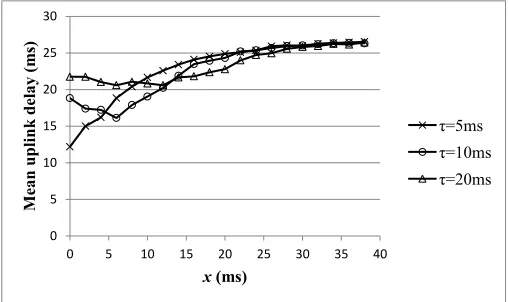
Fig. 8 illustrates the mean uplink delay as a function of the predictive resource allocation parameter x for an SR periodicity of TSR = 40ms and three values of inter-sensor propagation time, τ = 5ms, 10ms and 20ms. As x increases, the three curves converge on a mean uplink delay of approximately 26.5ms which, as explained earlier, is slightly higher than the expected mean uplink delay for TSR = 40ms when no predictive resource allocation is employed. The value of x that results in the minimum mean uplink delay varies from x = 0ms for τ = 5ms, x
[image:6.612.44.298.354.505.2]= 6ms for τ = 10ms and x = 12ms for τ = 20ms.
Fig. 8: Mean Uplink Delay as a Function of Predictive Resource Allocation Parameter x for an SR periodicity (TSR) of
40ms
If the inter-sensor propagation time τ is unknown, or the disturbance propagates at a variable speed, it is difficult to set the parameter x to achieve the minimum mean uplink delay. However, the graphs of Fig. 5 and Fig. 8 demonstrate that a significant reduction in mean uplink latency (relative to no predictive resource allocation) can be achieved by setting x = 0. However, this is at the expense of a significant increase in resource wastage due to unsuccessful predictive resource allocations as illustrated in Fig. 7.
V.CONCLUSIONS
In this paper, we have introduced the concept of predictive uplink resource allocation in LTE for M2M applications in
which a group of related devices such as sensors exhibit correlation in their traffic patterns. When receiving a Scheduling Request (SR) or data packet resulting from an earlier predictive resource allocation from one device, the eNodeB examines the eligible neighbors of that device to determine whether they might benefit from a predictive resource allocation (as opposed to waiting for the neighbors to send their own SRs according to their scheduled SR opportunities). We demonstrated how the minimum uplink latency can be reduced from 6ms to 5ms and how the mean latency can be reduced by greater than 50% (for an SR periodicity of TSR = 80ms and an inter-sensor propagation time τ = 10ms) using this method. Of course, there is a risk with predictive resource allocation that resources will be assigned to a device before it has a packet to send, in which case the resources will be wasted.
Further work will focus on developing a mathematical model for predictive uplink resource allocation in LTE and refining the predictive resource allocation algorithm e.g. to afford each device multiple predictive resource allocations (if necessary) in response to some propagating event and to incorporate the effect of DRX.
ACKNOWLEDGMENT
This work has been supported by Ausgrid and the Australian Research Council (ARC).
REFERENCES
[1] 3GPP TR 25.913 V8.0.0 (2008-12), “Requirements for Evolved UTRA (E-UTRA) and Evolved UTRAN (E-UTRAN)", Release 8
[2] Jason Brown and Jamil Y. Khan, “Performance Comparison of LTE FDD and TDD Based Smart Grid Communications Networks for Uplink Biased Traffic”, Smart Grid Communications (SmartGridComm), 2012 IEEE International Conference on, 5-8 Nov. 2012
[3] 3GPP TS 36.331 V8.15.0 (2011-09), “Evolved Universal Terrestrial Radio Access (E-UTRA); Radio Resource Control (RRC); Protocol specification”, Release 8.
[4] 3GPP TS 36.321 V8.10.0 (2011-09), “Evolved Universal Terrestrial Radio Access (E-UTRA); Medium Access Control (MAC) protocol specification”, Release 8
[5] 3GPP TS 36.213 V8.8.0 (2009-09), “Evolved Universal Terrestrial Radio Access (E-UTRA); Physical layer procedures”, Release 8 [6] Teixeira, M.A.; Guardieiro, P.R.; "A predictive scheduling algorithm for
the uplink traffic in IEEE 802.16 networks," Advanced Communication Technology (ICACT), 2010 The 12th International Conference on , vol.1, no., pp.651-656, 7-10 Feb. 2010
[7] El Gamal, H.; Tadrous, J.; Eryilmaz, A.; "Proactive resource allocation: Turning predictable behavior into spectral gain," Communication, Control, and Computing (Allerton), 2010 48th Annual Allerton Conference on, Sept. 29 2010-Oct. 1 2010
[8] Tadrous, J.; Eryilmaz, A.; El Gamal, H.; Nafie, M.; "Proactive resource allocation in cognitive networks," Signals, Systems and Computers (ASILOMAR), 2011 Conference Record of the Forty Fifth Asilomar Conference on, pp.1425-1429, 6-9 Nov. 2011
[9] 3GPP TS 36.101 V8.16.0 (2011-12), “Evolved Universal Terrestrial Radio Access (E-UTRA); User Equipment (UE) radio transmission and reception", Release 8
[10] V. Erceg et al., “An empirically based path loss model for wireless channels in suburban environments”, IEEE JSAC, vol.17, no.7, July 1999, pp. 1205-1222.
0 5 10 15 20 25 30
0 5 10 15 20 25 30 35 40
Me
an
u
p
li
n
k
d
ela
y (m
s)
x(ms)