University of Southern Queensland
Faculty of Health, Engineering & Sciences
Wireless Communication Between DataNode Systems
A dissertation submitted by
C. Johnstone
in fulfilment of the requirements of
ENG4112 Research Project
towards the degree of
Bachelor of Computer Systems Engineering
Abstract
There is a growing demand for devices to be capable of wireless communication over
long distances, especially in remote areas where a wired connection is not viable. Using
an SMS or call system is expensive, therefore there is a need for a cost and
low-power alternative to achieve the wireless communication necessary for the DataWatch
data logging systems.
DataWatch is a line of data loggers developed by Rimik Pty Ltd, and has so far only
been communicating through either direct connection or through a cellular modem.
These systems are capable of providing much more with the addition of a low-cost,
low-power wireless interface. However, there are a number of different options
commer-cially available to provide a wireless interface between devices, and therefore the most
appropriate device must be determined.
As a result of the conducted research and the resources available, ZigBee was decided
to be the most ideal wireless interface to implement into the DataWatch nodes.
Support for the wireless devices has been programmed into the firmware of the DataWatch
system and is currently in the process of being tested to ensure that it provides all that
is required of it.
For the intended application, ZigBee has thus far been functioning as intended with
University of Southern Queensland
Faculty of Health, Engineering and Sciences
ENG4111/2
Research Project
Limitations of Use
The Council of the University of Southern Queensland, its Faculty of Health,
Engineer-ing and Sciences, and the staff of the University of Southern Queensland, do not accept
any responsibility for the truth, accuracy or completeness of material contained within
or associated with this dissertation.
Persons using all or any part of this material do so at their own risk, and not at the
risk of the Council of the University of Southern Queensland, its Faculty of Health,
Engineering and Sciences or the staff of the University of Southern Queensland.
This dissertation reports an educational exercise and has no purpose or validity beyond
this exercise. The sole purpose of the course pair entitled “Research Project” is to
contribute to the overall education within the student’s chosen degree program. This
document, the associated hardware, software, drawings, and other material set out in
the associated appendices should not be used for any other purpose: if they are so used,
it is entirely at the risk of the user.
Prof F Bullen
Dean
Certification of Dissertation
I certify that the ideas, designs and experimental work, results, analyses and conclusions
set out in this dissertation are entirely my own effort, except where otherwise indicated
and acknowledged.
I further certify that the work is original and has not been previously submitted for
assessment in any other course or institution, except where specifically stated.
C. Johnstone
0050086336
Signature
Acknowledgments
I would first and foremost like to extend thanks to my workplace, Rimik Pty Ltd. First,
for giving me the great opportunity of being able to do my final year project through
work, such that I may be able to give something back to them while I finish my degree.
If it weren’t for the encouragement and assistance from Luke - my employer - and
Stephen - my colleague at work - I would have had a much harder time working through
this project.
I would also like to extend thanks to Dr. Alexander Kist, for having to put up with
my terrible study habits and the like and for providing useful feedback with regards to
my project. I was probably quite a pain!
On a more personal note, I’d like to thank my friends and my housemates for giving
me an escape every now and then with regards to either hanging out or playing games
together - it really helps with reducing stress levels.
I would also like to extend a huge acknowledgement to God, as without Him I would
have never been able to finish this thesis. I hope that my work has been glorifying to
Him and that I can always show his characteristics through me, even though I fail so
many times to do so. The prayers of my friends in Church and outside of Church have
been invaluable, and I can’t fully express how appreciative I am of this.
C. Johnstone
University of Southern Queensland
Contents
Abstract
i
Acknowledgments
iv
List of Figures
xiii
List of Tables
xv
Chapter 1
Introduction
1
1.1
Broad Aims . . . .
2
1.2
Specific Objectives . . . .
2
1.3
Overview of the Dissertation
. . . .
3
Chapter 2
Background
5
2.1
Chapter Overview . . . .
5
2.2
What are DataNode Systems? . . . .
5
2.2.1
Environmental Monitoring . . . .
5
2.2.2
Data Logging . . . .
6
CONTENTS
vi
2.3
Previous DataNode Wireless Communication . . . .
7
2.3.1
Short-range XBee
. . . .
7
2.3.2
Modems . . . .
9
2.4
Applications . . . .
11
2.4.1
Remote Output Control . . . .
11
2.4.2
Status Updates . . . .
13
2.4.3
Data Collection . . . .
13
2.5
Requirements Analysis . . . .
13
2.5.1
Hardware Requirements . . . .
14
2.5.2
Software Requirements . . . .
15
2.5.3
User Requirements . . . .
15
2.5.4
Functional Requirements . . . .
16
2.5.5
Non-Functional Requirements . . . .
16
2.5.6
Future Requirements . . . .
16
2.6
Chapter Summary . . . .
17
Chapter 3
Literature Review
18
3.1
Chapter Overview . . . .
18
3.2
Bluetooth . . . .
18
3.2.1
Operating Frequencies . . . .
18
3.2.2
Radio Classes . . . .
19
CONTENTS
vii
3.2.4
Typical Applications . . . .
20
3.2.5
Routing Algorithms . . . .
20
3.2.6
Security . . . .
21
3.2.7
Summary . . . .
21
3.3
Wi-Fi . . . .
22
3.3.1
Operating Frequencies . . . .
22
3.3.2
Power Consumption . . . .
22
3.3.3
Typical Applications . . . .
23
3.3.4
Security . . . .
23
3.3.5
Range . . . .
24
3.3.6
Summary . . . .
24
3.4
ZigBee . . . .
25
3.4.1
Operating Frequencies . . . .
25
3.4.2
Power Consumption . . . .
25
3.4.3
Range . . . .
26
3.4.4
Security . . . .
27
3.4.5
Layers . . . .
27
3.4.6
Typical Applications . . . .
28
3.4.7
Network Structure . . . .
28
3.4.8
Routing Algorithms . . . .
29
CONTENTS
viii
3.5
Evaluation . . . .
30
3.6
Chapter Summary . . . .
32
Chapter 4
Methodology
33
4.1
Chapter Overview . . . .
33
4.2
Development Methodology . . . .
33
4.3
Task Analysis . . . .
34
4.3.1
Undertake Requirements Analysis . . . .
35
4.3.2
Potential Use-Cases . . . .
35
4.3.3
Specification . . . .
36
4.3.4
Evaluation . . . .
36
4.3.5
Hardware Selection . . . .
36
4.3.6
Implementation . . . .
37
4.4
Resource Requirements
. . . .
37
4.4.1
Hardware Implementation . . . .
37
4.4.2
Software Development Tools . . . .
38
4.4.3
Testing Equipment . . . .
39
4.5
Consequential Effects . . . .
39
4.5.1
Sustainability . . . .
39
4.5.2
Safety . . . .
40
4.5.3
Ethics . . . .
41
CONTENTS
ix
4.6.1
Risk Identification . . . .
41
4.6.2
Risk Control . . . .
42
4.7
Project Timeline . . . .
43
4.8
Chapter Summary . . . .
44
Chapter 5
Design
45
5.1
Chapter Overview . . . .
45
5.2
Hardware Support . . . .
45
5.3
Software Support . . . .
46
5.4
Routing Protocols . . . .
46
5.5
Security . . . .
47
5.6
Power Consumption and Sleep . . . .
47
5.6.1
Normal Mode . . . .
48
5.6.2
Asynchronous Pin Sleep Mode . . . .
48
5.6.3
Asynchronous Cyclic Sleep Mode . . . .
49
5.6.4
Asynchronous Cyclic Sleep with Pin Wake Up Mode . . . .
49
5.6.5
Synchronous Sleep Support Mode . . . .
49
5.6.6
Synchronous Cyclic Sleep Mode . . . .
50
5.6.7
Conclusions . . . .
50
5.7
Design of Transmission Protocol . . . .
50
5.7.1
Transmission Mode . . . .
51
CONTENTS
x
5.8
Design of Packets . . . .
54
5.8.1
Data Packets . . . .
55
5.8.2
Error-Checking Packets . . . .
55
5.9
Application Design . . . .
58
5.9.1
Remote Output Control . . . .
58
5.9.2
Status Updates . . . .
61
5.10 Field Testing Procedure . . . .
61
5.10.1 Antennas . . . .
61
5.10.2 Variable Transmit Power
. . . .
62
5.10.3 Received Signal Strength Indicator, RSSI . . . .
62
5.10.4 Horizon Implications . . . .
62
5.10.5 Transmit Power Tests . . . .
63
5.10.6 Range Implications on Data Throughput . . . .
63
5.11 Chapter Summary . . . .
64
Chapter 6
Implementation
65
6.1
Chapter Overview . . . .
65
6.2
Hardware Implementation . . . .
65
6.3
Sleep Mode . . . .
68
6.3.1
Cycle Duration . . . .
70
6.4
Security . . . .
70
CONTENTS
xi
6.5.1
Packet Payload Size . . . .
71
6.5.2
Packet Creation
. . . .
72
6.6
Application Implementation . . . .
74
6.6.1
Remote Output Control . . . .
74
6.6.2
Status Updates . . . .
79
6.7
Communication Range Evaluation . . . .
83
6.7.1
Field Test Results . . . .
83
6.7.2
Conclusions . . . .
85
6.8
Chapter Summary . . . .
87
Chapter 7
Conclusions and Further Work
88
7.1
Chapter Overview . . . .
88
7.2
Achievement of Project Objectives . . . .
88
7.3
Further Development . . . .
89
7.4
Chapter Summary . . . .
89
References
90
Appendix A Project Specification
94
Appendix B Project Management Information
96
B.1 Resource Planning . . . .
97
B.2 Consequential Effects . . . .
98
CONTENTS
xii
B.3.1 Risk Identification . . . .
98
B.3.2 Risk Control . . . .
99
B.4 Requirements Analysis Document (RAD) . . . 101
B.5 Timeline . . . 105
Appendix C Datasheets and Manuals
107
C.1 ”XBee-PRO Manual” . . . 108
List of Figures
2.1
NCEA Developed XBee Communications. . . .
8
2.2
SMS Messaging. . . .
10
2.3
Circuit Switched Data. . . .
11
2.4
Pump Control Application. . . .
12
2.5
Pump Control Use Case Diagram. . . .
12
2.6
Data Collection Use Case Diagram. . . .
14
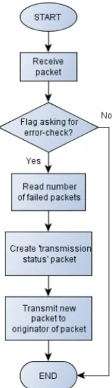
5.1
Functionality of Packet Error-Checking . . . .
58
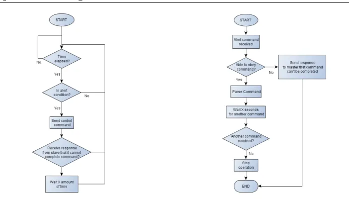
5.2
‘Master’ Node Operation . . . .
60
5.3
‘Slave’ Node Operation . . . .
60
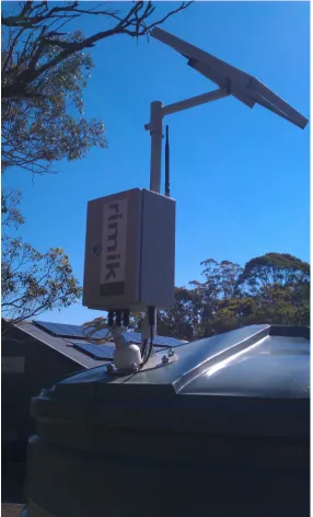
6.1
LevelWatch External view . . . .
66
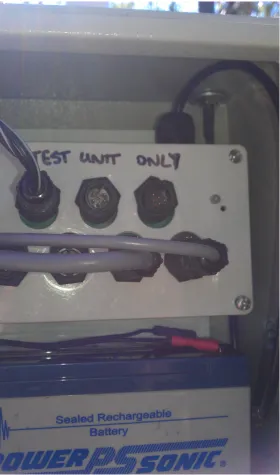
6.2
LevelWatch Internal view . . . .
67
6.3
Temporary XBee RF Module enclosure . . . .
69
6.4
LevelWatch Water Tank probes . . . .
81
6.5
Level/PumpWatch Status Updates . . . .
82
LIST OF FIGURES
xiv
List of Tables
3.1
Power Consumption of Bluetooth Classes . . . .
20
3.2
Power Consumption of Wi-Fi . . . .
23
3.3
Characteristics of Bluetooth, Wi-Fi, and ZigBee . . . .
30
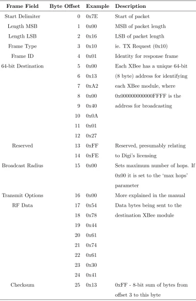
5.1
TX Request Packet . . . .
56
6.1
Data Packet requesting Error-Check . . . .
75
6.2
Error-Checking Packet Response . . . .
76
6.3
2.1 dB Antenna with Lowest Transmit Power . . . .
84
6.4
2.1 dB Antenna with Highest Transmit Power . . . .
85
Listings
Chapter 1
Introduction
There is a growing demand in the world today for the ability to communicate between
devices over large distances, especially out in remote areas such as on properties or
large farms, for the purpose of monitoring various elements such as weather, water
flow, and tank or bore water levels. There are various businesses developing in the area
of wireless communication, such as Maxon and and Observant
Companies such as Maxon and Observant are both developing in the area of wireless
communication, with products that are capable of achieving communication over varied
distances for a number of tasks such as water and irrigation monitoring.
Within the company Rimik Pty Ltd, who design and manufacture specialised electronic
equipment such as Cone Penetrometers and Data Logging systems, wireless
commu-nication has primarily been achieved through the use of modems to provide an SMS
(Short Message Service) interface. Whereas this current system of wireless
commu-nication works and does its job, it is incapable of performing tasks such as large or
extended data downloads over several systems at one location. This is costly with an
SMS system, and as a result a different method of wireless communication is desired.
By taking advantage of wireless technologies, the overall cost for monitoring several
different systems can be drastically reduced. For example, a group of 5 Data Logging
systems owned by one customer on a farm could be changed from using 5 different
Modems, each with different SIM cards and credit, to using only a single Modem to
1.1 Broad Aims
2
with the Modem system to transfer information that a user wants to collect. More
information on this will be discussed in Chapter 2.
Development in this area of technology will be able to open up a much larger market
for sales and pave the way for future developments to further increase the capability of
wireless communication.
1.1
Broad Aims
The primary aims of this project is to conduct research into the area of wireless
com-munication technologies and their performance, tabulate the results and a comparison
between major wireless technologies, and determine which solution will be the most
applicable for implementation into a specific, real-world system. Once this initial
re-search has been completed, the chosen wireless technology will be designed, developed,
and implemented into a currently existing Data Logging system, known as DataNodes.
The wireless communication technology must be able to satisfy a number of
require-ments, such as the ability to transfer logging data between devices and to provide
output control features.
Upon the completion of this project, it is intended that the DataNode system will have
a fully functional, robust, and working wireless interface that is of a quality satisfactory
for the market, with the capability to be developed even further.
1.2
Specific Objectives
The first and foremost objective for this project is to conduct a comprehensive literature
review into the main technologies that are available that can achieve localised wireless
communication. The information gathered from this review will then be used to develop
a table of information on each of the devices that can then be applied to a set of weighted
requirements to be able to determine which direction would be the most effective for
accomplishing the task of getting wireless communication between the devices.
imple-1.3 Overview of the Dissertation
3
menting it with currently existing DataNodes (Explained in Chapter 2). If required,
hardware will be developed to be able to interface the chosen device required for wireless
communication to the DataNode so that it may be interacted with using the firmware
of the Node itself.
For the chosen technology to work with the DataNodes, the firmware of the devices
must be programmed in order to work with and use the wireless technology. As a
result, programming will then need to be undertaken in order to permit the DataNode
to interface with the chosen wireless device in order to effectively communicate with
other DataNodes as well as a user’s Personal Computer (PC), and if time permits, a
user’s wireless device (such as a mobile phone).
If time permits, perform field testing to ensure that the communication behaves as it
is intended in an actual field situation.
In summary, the objectives of this Project consists of the following:
•
Conduct a comprehensive literature review into Wireless Communication devices
•
Produce an evaluation of the wireless technologies available
•
Make an informed decision as to which technology is the most appropriate for the
chosen target
•
If necessary, develop hardware for interfacing with current DataNodes
•
Program into the DataNode firmware support for the chosen device to achieve
communication
•
If time permits, perform field testing on the end result of the Wireless
Commu-nication between DataNodes
1.3
Overview of the Dissertation
This dissertation is organized as follows:
Chapter 2
has background information relating to the project, including previous
1.3 Overview of the Dissertation
4
Chapter 3
goes through the different wireless technologies available and evaluates
various documents and articles on them, in order to come to an overall conclusion
as to which wireless interface is the most suitable for use in the later stages of
the project work
Chapter 4
outlines the methodologies for the research and development of this project.
Also touched on in this Chapter are the potential consequential effects and risks
that may arise throughout the duration of the project
Chapter 5
goes through the different stages undertaken throughout the design process
of the project
Chapter 6
shows the stages taken during implementation of the project and explains
each step along the way
Chapter 7
concludes the dissertation and suggests further work in the area of Wireless
Chapter 2
Background
2.1
Chapter Overview
This Chapter goes through different areas of background information relating to the
Project. It includes information such as what DataNode systems and nodes are, the
previous wireless communication work relating to the DataNode range of systems, some
intended applications for the project, and information about a requirements analysis
performed for the project.
2.2
What are DataNode Systems?
DataNode is a line of Data-Logging systems developed and sold by the company Rimik.
These systems are deployed in the field and monitor an environment depending on the
type of DataNode system deployed and are capable of logging useful information over
extended periods of time. This section will be discussing the major features that
DataNodes provide.
2.2.1
Environmental Monitoring
These units can utilise eight different Input/Output (I/O) ports to monitor various
2.2 What are DataNode Systems?
6
time that it takes for each DataNode logger to fill up the entirety of its on-board
data-flash chips can be up to several years before the circular buffer starts to overwrite the
oldest data.
Various environmental sensors are supported with the DataNodes, such as Rainfall
me-ters, Anemometers (Detects wind speed), Wind Vanes (Wind Direction), Temperature,
and Relative Humidity sensors.
The applications for this type of DataNode include, but are not limited to:
•
Monitor the status of the weather in an area
•
Monitor a Bore’s water level and pump flow rate
•
Monitor a water Tank or Channel’s water level
•
Track and monitor an Irrigator and its flow of water
2.2.2
Data Logging
One of the primary features of DataNodes are that they are all capable of logging
collected data. At an interval that can be changed by the user (typically 5 minutes)
the system will read each of the sensors that are attached to make a log into the system’s
on-board data-flash chip. This chip is capable of holding approximately 7-8 readings
per page of flash, where there are 8191 pages of flash available for use on the chip. This
allows for more than 55,000 log entries on each DataNode before running out of free
space. At a logging interval of 5 minutes, this means that it can take up to 5,500 hours
before the stored data will either need to be cleared or will simply start to overwrite
itself.
All of this data is capable of being downloaded by the user using a specially designed
Graphical User Interface, maintained and updated by Rimik.
2.2.3
Alerts
Certain types of DataNodes have support for providing the user alerts when certain
2.3 Previous DataNode Wireless Communication
7
has potentially gone wrong with, for example, their irrigator. The advantages of having
this is when the system is deployed several kilometres from a farmer’s home, to reduce
the chances of having to drive a long distance to check the system, and to ensure that
the system is still running as intended without having to regularly check it to ensure
that it is still funtional.
One of the main uses of the alert system is to inform a user when a DataNode has
pow-ered itself down, which can imply that something could have gone wrong (for example,
a lightning strike causing power issues, or solar panels not providing enough power to
keep the system running).
Continued work is being done to support a larger variety of alerts in the systems.
2.3
Previous DataNode Wireless Communication
There has been work done previously with DataNodes in an attempt to develop a
wireless communication interface between two nodes (Point to Point). The previous
methods of achieving wireless communication were to communicate via short range
ZigBee devices made by Digi called XBee Modules, and a system that made use of
Modems to provide an SMS interface.
2.3.1
Short-range XBee
This work was done primarily through the Research and Development department of
the National Centre for Engineering in Agriculture (NCEA) based at the University of
Southern Queensland, Australia.
This work was based around Digi’s ZigBee modules that are known as XBee, or XBee
PRO. These modules are available in two different frequency bands - 2.4 GHz and 900
MHz. These two frequency bands have their own advantages and disadvantages to their
use, and these will be discussed in section
??
on page
??
At the time these were being developed, both the 2.4 GHz and the 900 MHz versions
of the Modules were limited in their range. According to Steve Rees of NCEA, the
2.3 Previous DataNode Wireless Communication
8
MHz (Commonly longer range than 2.4 GHz) would not be able to reach distances that
much further than the 2.4 GHz module.
This development of Wireless Communication through ZigBee was done as a Proof
of Concept as opposed to a polished, marketable feature, and there was no protocol
available at the time to achieve what was needed for the communication. As an example,
the Coordinator Node that was developed by the NCEA was only developed to be a
proof of concept as well (Hogan, L. Rimik Pty Ltd 2013). As a result, the NCEA
developed their own protocol in order to packetise and transfer information between
Nodes. Alongside this, the XBee Modules in use at the time had no support for
providing a Mesh Network, which limited the wireless communication to Point-to-Point
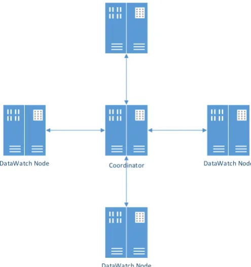
(Otherwise known as a ’Star’ Network) only. A simple diagram to show how these
work has been provided in Figure 2.1. In this figure, each DataNode has a single line
of communication back to the Coordinator and the Coordinator alone, with the nodes
being incapable of communicating with each other.
Coordinator
DataWatch Node
DataWatch Node
DataWatch Node
[image:25.595.167.415.403.666.2]DataWatch Node
2.3 Previous DataNode Wireless Communication
9
2.3.2
Modems
Currently widely used in DataNodes to achieve a communication interface is the use of
Cellular Modems, which provided two methods of being able to communicate with the
Node that the modem is connected to. This are:
SMS (Short Message Service) messages
to transfer packets of text to and from
a Node (Commonly used to send simple commands with output small enough to
fit in an SMS message)
Circuit Switched Data calls
to provide an interface similar to a direct serial
con-nection to a Node
Short Message Service (SMS)
For the SMS message feature to work, the user must type in a command into an
SMS message on their mobile phone and send it through to the mobile phone number
attached to the SIM card stored within the Modem. Once the modem has received
this command, it will then forward the data it has received through a serial cable to
an RS-232 Port on the DataNode. The Node then parses the command received and if
the response involves sending an SMS message back to the user, it will form an SMS
packet and send it back through the cable to the modem so that it may be sent back
to a specified mobile phone number.
This system functions well for being able to achieve wireless communication but
unfor-tunately has its own disadvantages to its use. Each message sent to or from the modem
costs the user on their mobile phone plan that they have, and also have a limit to how
much data can be included in each message. The message size depends on the data
coding scheme as follows:
•
160 characters for 7-bit scheme
•
140 characters for 8-bit scheme
2.3 Previous DataNode Wireless Communication
10
Due to this limiting factor, the SMS system should only be used to transfer data that
falls within these limits, otherwise the cost of each transmission will increase. As a
result, it is impossible to be able to download the logging data stored on a DataNode,
as the size of the data can add up to 4 MB, which would cost a lot of money to transfer.
At $0.25 per message with a maximum of 160 bytes per message, it would cost $6553.60
to transfer 4 MB of data. In Figure 2.2, a simple diagram has been provided to show
the basic function of how the SMS system works. The user uses their mobile phone to
send a text message to the DataNode’s modem, which is then passed to the Node itself
through the RS-232 serial port.
User
Mobile Phone Satellite
Node s Modem
DataWatch Node
Mobile Phone Satellite
Figure 2.2: SMS Messaging.
Circuit Switched Data (CSD)
For the Circuit Switched Data feature to work, the user utilises a Graphical User
Interface to connect a Data call to the mobile phone number attached to the SIM
in the Node’s modem. The Modem will then automatically pick up the call and the
connection then emulates a direct serial connection as if the Node were connected
directly to a computer with a cable. The performance of the call is then dependent on
the Baud rates used for the communication (Primarily 9600 Baud) as well as how long
the call is connected for, which can be costly for the user if they remain connected for
an extended period of time. Figure 2.3 shows a basic view of how this works. The user
uses the DataNode Graphical User Interface with their modem to make a ’phone call’ to
the phone number associated with the Node’s modem, and once the Node picks up the
call it will ’connect’ the two modems. All data then transferred to the user’s modem
is transferred through to the other modem, and similarly for the other direction. This,
2.4 Applications
11
User
User s Modem
Node s Modem
DataWatch Node
Figure 2.3: Circuit Switched Data.
2.4
Applications
Wireless Communication between DataNodes has a number of different applications
that have been the primary drive behind this project. With the addition of working,
low-cost, low-power wireless communication, a number of new avenues have opened up
to expand into to improve upon the currently existing design and expand the product’s
market. This section will be going over a few select applications intended for the
DataNode system.
2.4.1
Remote Output Control
One of the first applications intended to be an outcome of this Project is the ability to
be able to remotely control an output, which could in itself be capable of controlling
a number of different devices. The primary intended device for control is currently a
water pump, to maintain the water levels within anything that requires water pumped
to it, such as Water Tanks.
One example of this application are two different DataNodes - a LevelWatch and a
PumpWatch. The PumpWatch would be set up on a farmer’s property at their bore,
attached to a pump system and with a water level meter within the bore itself. At a
Water Tank somewhere else on the property would be set up with a LevelWatch system
on it, with water level probes within the tank to monitor the water level. A diagram
has been provided to show the basic operation of this application in Figure 2.4. With
the LevelWatch system, the level sensors set up within the tank will sense the water’s
current level and monitor it. The typical usage of this is with two water probes lowered
into the tank, one used to determine a ’High’ water level and the other to determine a
’Low’ water level. When the water has lowered below the ’Low’ sensor, the LevelWatch
system detects this and sends a message over the wireless interface to the PumpWatch
2.4 Applications
12
to being at an acceptable level as set by the user. If the PumpWatch detects with its
water level sensor that its own water supply is too low, it will stop pumping water and
send a message to the LevelWatch system to notify it that it does not have sufficient
water.
TankWatch
PumpWatch attached to Bore
Figure 2.4: Pump Control Application.
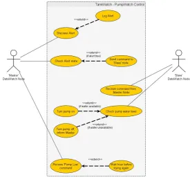
Figure 2.5 shows a Use Case diagram to assist in explaining the operation of the Nodes
communicating to achieve remote pump control. It shows how the two Nodes (In this
case, a LevelWatch communicating with a PumpWatch to control the PumpWatch’s
[image:29.595.152.428.449.705.2]pump) communicate to effectively control the PumpWatch’s pump.
2.5 Requirements Analysis
13
2.4.2
Status Updates
Another intended application for use with a wireless interface is the ability to regularly
send updates to a central location, such as a user’s home computer. The intended usage
for this is to be able to provide a diagram representation of the DataNode network and
to show the current status of each of the Nodes on the screen in an easy-to-read fashion.
This will allow the user to monitor the behaviour of the network over an extended period
of time to see how it is behaving, instead of receiving the occasional update.
2.4.3
Data Collection
Another of the primary features that are intended to be implemented with the
intro-duction of a wireless communication interface in the DataNode is the ability to collect
data from a number of DataNodes out in the field, periodically.
This can be done in a number of different ways, such as having a central ’Coordinator’
node collect the data periodically from the other nodes in the network and storing this
on its own internal Flash ready to be downloaded by a user, or by having the user’s
computer behave like a Base Station (or ’sink’) for the network, where all of the log
data is transmitted to the sink where it will save the data in files as it is received, and
potentially in different folders depending on which node it has come from (For example,
have a folder for each type of DataNode out in the field, or a folder for each Node’s
serial number).
Shown in Figure 2.6 is a Use Case Diagram to assist in the explanation of the
opera-tion of DataNodes communicating with each other to achieve periodic Data Collecopera-tion
within the network. It shows how the ’Coordinator’ or ’Sink’ will periodically
commu-nicate with each of the nodes in the network to download the latest log information
and save it within whatever target location is used.
2.5
Requirements Analysis
As this Project is based within a company that intends to market this product to
2.5 Requirements Analysis
14
Figure 2.6: Data Collection Use Case Diagram.
outcome of this Project satisfies the specific criteria for the system. An overview of
the Document has been provided and a copy of the document itself an be found in
Appendix B.4 on page 101.
2.5.1
Hardware Requirements
•
Two-way communication between DataNodes including complete stored memory
download of 4 MB
•
Multichannel capability
•
Minimum transmission rate of 9600 Baud
•
Desired transmission rate of 38400 Baud to match Node capability
•
Transmission range of no less than 5km but up to 40kms
•
Compatibility with existing DataNode hardware
•
Capable of being fitted appropriately in a DataNode Enclosure or built into a
DataNode
•
Flexibility in external Antenna placement with limited signal loss
•
Power consumption to be within existing battery and solar recharge capability
2.5 Requirements Analysis
15
2.5.2
Software Requirements
•
Non proprietary
•
Fits within existing language constraints
•
Efficient use of programming space
•
Current DataNode has:
•
Maximum of 65535 bytes of program space
•
Maximum of 4096 bytes of data space
•
Predefined transmission protocols which fit within existing node software
func-tionality
•
Potential for greater functionality than existing use requires
•
Capacity for transmission error detection and correction (robustness in platform)
•
Easy to maintain
2.5.3
User Requirements
•
Reliably transmits messages or data to points of access
•
Reliably transmits data on request
•
Low or no interference from existing equipment
•
Ability to transmit signals that could be used for control of connected equipment
(to a PC or second Node)
•
Affordable - Low or no cost “local” transmission
•
Low power consumption
•
Minimum of 5km line-of-sight transmission with a preference of whole farm
cov-erage
2.5 Requirements Analysis
16
2.5.4
Functional Requirements
•
Wireless routing capabilities such as “meshing” to extend transmission range
•
Automated Node discovery
•
Ability to re-configure nodes via wireless transmission
•
Node to Node communication
•
PC to Node communication
2.5.5
Non-Functional Requirements
•
Easy to understand, use and repair
•
Reliable and robust for rural (dusty) environments
•
Secure, physically lockable system
•
Portability - can be relatively easily re-located
•
Performance matches or exceeds existing systems of similar functionality.
2.5.6
Future Requirements
•
Remote output control
•
Periodic information downloads to store logged data if necessary
2.6 Chapter Summary
17
2.6
Chapter Summary
In this chapter, the background information regarding DataNode Systems and Nodes
has been explained to reduce any potential confusion as to what DataNodes are and
what they do. Included here also are a few examples of intended applications for
DataNodes for developing within or after this project, along with an overview of a
Chapter 3
Literature Review
3.1
Chapter Overview
There are many different options available to achieve wireless communication. In this
chapter, a number of these solutions will be researched to compile a list of information
about each in order to make an informed decision on which direction to take. After
a decision has been made, the chosen solution will be programmed into the current
DataNode firmware for further testing.
Concluding this chapter will be recommendations on which wireless technology should
be implemented into DataNodes.
3.2
Bluetooth
Bluetooth is a Wireless protocol that was developed in 1994 by the Swedish company
Ericsson. The name ’Bluetooth’ was originally just used as a Codename for the project,
and it eventually “stuck”.
3.2.1
Operating Frequencies
Bluetooth technology operates within the unlicensed ISM (Industrial, Scientific, and
3.2 Bluetooth
19
available in most countries where this band is unlicensed and free to use.
To assist with the issue of interference, Bluetooth makes use of what is known as an
adaptive frequency hopping (AFH), which allows the technology to be able to detect
the spectrum being used by any nearby devices and change to make use of a spectrum
not currently being occupied. This capability hops among 79 frequencies at 1 MHz
intervals, which allows for a high amount immunity to potential interference that can
be caused by other Bluetooth devices that may be in the vicinity.
3.2.2
Radio Classes
According to the Bluetooth SIG’s website, there are three primary classes of Bluetooth
radios that are commonly used, each with their own different applications.
These are as follows:
Class 3 Radios
- have a range of up to 1 metre or 3 feet
Class 2 Radios
- most commonly found in mobile devices - have a range of 10 metres
or 33 feet
Class 1 Radios
- used primarily in industrial use cases - have a range of 100 metres
or 300 feet
3.2.3
Power Consumption and Range
Bluetooth boasts that the technology is designed around being very low-power and
claim that their Class 2 radios found in mobile phones uses 2.5 mW of power. To
accompany this, the specifications for Bluetooth also allow for the capability of powering
down radios when they are inactive, drawing less power.
The Special Interest group also states in their Product Development overview that
there also exists a more low-power technology Bluetooth that is optimised for devices
that need ”maximum battery life instead of a high data transfer rate” that consumes
3.2 Bluetooth
20
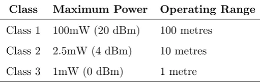
Table 3.1: Power Consumption of Bluetooth Classes
Class
Maximum Power
Operating Range
Class 1
100mW (20 dBm)
100 metres
Class 2
2.5mW (4 dBm)
10 metres
Class 3
1mW (0 dBm)
1 metre
A blogging website called “Bluetooth Insight”, which provides news, updates, reviews,
and useful information regarding Bluetooth, quoted the following for the power
con-sumption of each of the three Classes of Bluetooth (Bluetooth Insight 2008). With each
of these classes also is a mention of the nominal range one can expect from each class
of Bluetooth.
3.2.4
Typical Applications
Bluetooth is based on a wireless radio system that was designed for short-range and
‘cheap’ devices, primarily for the purposes of replacing cables for different electronic
peripherals (Jin-Shyan Lee 2007).
Such devices include, but are not limited to, the following:
•
Computer keyboards
•
Computer mice
•
Mobile phone headsets
•
Music players
3.2.5
Routing Algorithms
There are two topologies available in Bluetooth networks, called Piconet and Scatternet.
A Piconet is a WPAN (Wireless Personal-Area-Network) where one Bluetooth device
serves as a master in the piconet with one or more other Bluetooth devices serving
as slaves in the network. All of the devices within the Piconet are synchronised with
each other using the clock of the master device, and all of the slave devices can only
3.2 Bluetooth
21
A Scatternet is a collection of working Bluetooth piconets that are overlapping in time
and space. Within this configuration, Bluetooth devices can participate in several
piconets at the same time, resulting in a higher area coverage, and each device in a
scatternet can be a slave to many piconets but master to only one (Jin-Shyan Lee 2007).
3.2.6
Security
With the release of Bluetooth Version 4.0, a number of security issues have been dealt
with, however with the older versions of Bluetooth there still remains security issues as
it is only provided with the latest version of Bluetooth (Sandhya S n.d.).
Where the older versions of Bluetooth made use of a 4 digit PIN or ‘fixed PIN Passive
Eavesdropping Protection’, the newer version of Bluetooth makes use of a 16
alphanu-meric PIN (Effectively 128-bit Encryption). This helps greatly in the chance that
hacking may occur, as a 4 digit PIN can only support 10000 different PINs, whereas
a 16 alphanumeric PIN provides much more possible combinations, making it more
difficult to crack the code.
3.2.7
Summary
To briefly summarise what Bluetooth has to offer for wireless communication, it is a
”short-range communications technology” (Bluetooth Special Interest Group 2013c).
With Security, Bluetooth offers a simple and effective method of securing Bluetooth
devices, using 16 alphanumeric PINs to secure devices, offering effectively 128-bit
en-cryption that most devices use.
In the area of networking, Bluetooth offers the capability to communicate between
devices through ”short-range ad hoc” networks otherwise known as piconets. Within
this piconet, only up to 8 different Bluetooth devices can communicate with each other
(One device can communicate with up to 7 other devices), which is largely a limiting
factor for the use of Bluetooth within this project.
Alongside this is the limited range capabilities of Bluetooth devices, with a quoted
3.3 Wi-Fi
22
not Bluetooth will be viable.
3.3
Wi-Fi
Wi-Fi standards and specifications are developed by a group known as the Wi-Fi
Al-liance, whose roots come from the organisation known as the Institute of Electrical and
Electronic Engineers (IEEE). According to the website for the Wi-Fi Alliance, in 1999
several visionary leaders had come together to form the global non-profit organisation
to help drive the use of high-speed wireless networking.
3.3.1
Operating Frequencies
There are two primary frequency bands that the Wi-Fi specification utilises, which are
2.4 GHz and 5 GHz (Wi-Fi Alliance 2013a). Both of these bands are unlicensed in most
countries, which means that it can be widely used in a number of countries without
having to worry about licensing issues with other frequency bands.
3.3.2
Power Consumption
W-Fi is designed to provide longer connection times to the nodes within the network,
and thus requires a substantial power supply.
In “A Comparative Study of Wireless Protocols: Bluetooth, UWB, ZigBee, and
Wi-Fi”, experimentation was undertaken into the area of power consumption between the
different wireless technology (Jin-Shyan Lee 2007).
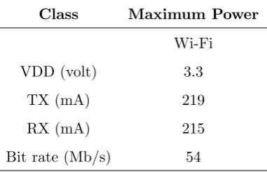
The following is an excerpt from the table provided in the paper.
As can be seen from the table, the transmit current (TX) is a high 219mA, with the
3.3 Wi-Fi
23
Table 3.2: Power Consumption of Wi-Fi
Class
Maximum Power
Wi-Fi
VDD (volt)
3.3
TX (mA)
219
RX (mA)
215
Bit rate (Mb/s)
54
3.3.3
Typical Applications
Wi-Fi is a standard used for wireless local area networks (WLAN), and can be used to
allow users to access the internet
The common use for Wi-Fi is to provide connectivity for a variety of different devices
within places such as homes, businesses, cities, and campuses. The Wi-Fi Alliance states
that the Wi-Fi products of today can ”do everything from sending email to streaming
video and linking international video conference - even linking you to the Internet from
a plane 10,000 feet in the air or just down the hallway” (Wi-Fi Alliance 2013a).
One of the likely best known uses for Wi-Fi is to provide a wireless connection to
the internet within homes, businesses, campuses, and the like. These applications
along with a number of others focus primarily on having the Wi-Fi device providing a
longer connection and a substantial power supply, due to power consumption
require-ments (Jin-Shyan Lee 2007).
3.3.4
Security
Over the years, Wi-Fi has been developing and improving upon the security of their
networks. Since Wi-Fi is one of the most widely used and trusted technologies in
the world (Wi-Fi Alliance 2012). The ”first generation” security solution that was
developed for Wi-Fi was Wired Equivalent Privacy (WEP), which was first introduced
in 1997 (Blank 2010). However, WEP security had flaws, such as users being able
to obtain the security key through analysing several keys that can share the same
3.3 Wi-Fi
24
The successor of the WEP security solution was the Wi-Fi Protected Access solution,
which was an interim security solution to address the vulnerabilities present within
WEP security while the Institute of Electrical and Electronic Engineers developed an
amendment and upgrade to WPA (Wi-Fi Alliance 2012).
The WPA security solution is founded on two key protocols, these being:
•
Advanced Encryption Protocol (AES)
•
IEEE 802.1X
AES is an encryption protocol that is used by the United States as well as other
gov-ernments in order to protect important information, such as confidential and classified
information.
IEEE 802.1X is a standard that is used within corporate networks in order to provide
a more robust authentication as well as sophisticated network access control.
The most commonly used method of authentication used is the Pre-Shared Key (Or
PSK), which is a security key that is shared only with devices that are permitted to
access the network.
3.3.5
Range
With regards to the range of a Wi-Fi network, the latest form of Wi-Fi technology
known as ”Wi-Fi CERTIFIED n” or ”Wireless-n” or 802.11n typically has a range of
up to 200 metres (Wi-Fi Alliance 2013b), which is aimed at being able to cover entire
homes.
For Wi-Fi that utilises 802.11a/b/g, the nominal range that can be expected is around
100 metres (Jin-Shyan Lee 2007).
3.3.6
Summary
Wi-Fi utilises an unlicensed frequency band, which means that it is supported in
3.4 ZigBee
25
power consumption of Wi-Fi, which requires a large amount of current in order to
transmit or receive. This results in Wi-Fi applications primarily having a substantial
power supply capable of providing enough power for it to run.
Depending on the chosen Wi-Fi specification of a, b, g, or n, the range can differ from
100 metres (a/b/g) to 200 metres (n).
Security has been an ever-advancing part of Wi-Fi, with a much more effective option
for securing a Wi-Fi network after previous security has been cracked.
3.4
ZigBee
ZigBee is built upon the IEEE 802.15.4 standards (ZigBee Alliance 2013c), which is
widely used in wireless sensor network applications due to its focus on providing
low-rate, wireless personal-area-network (LR-WPAN) capability (Shao Yong 2009).
3.4.1
Operating Frequencies
IEEE Standards and the ZigBee Alliance both state that it can operate within the
frequency ranges of 868.0-868.6, 902-928, and 2400-2483.5 MHz (Institute of Electrical
and Electronics Engineers (IEEE) 2009).
868.0-868.6 MHz
is commonly used for services such as Mobile and Radiolocation
(The use of radio waves for location)
902-928 MHz
has a variety of different uses, depending on the frequency used. This
includes GSM (For cellular mobiles), ISM, and radiolocation
2400-2483.5 MHz (2.4 GHz)
is primarily an unlicensed frequency band in most
countries, used primarily for ISM
3.4.2
Power Consumption
According to the comparative study conducted by Jin-Shyan Lee, Yu-Wei Su, and
3.4 ZigBee
26
and is suitable primarily for devices for low data-rate and limited battery supply. The
quoted values for testing with the CC2430 ZigBee Module resulted in a transmit current
of 24.7 mA and a receive current of 27 mA.
For ZigBee XBee devices by Digi International, a study found that power consumption
for End Device nodes could go as high as 25 mA when transmitting, and as high
as 3 mA when Idle. The manual for the XBee PRO (900 MHz variant) modules by
Digi International states that the power consumption when transmitting is configurable
from 60 mA (approximate) to as high as potentially 290 mA, with the receive current
typically around 29 mA. It also states that the current draw when the XBee module is
in Sleep mode is as low as 2.5
µ
A (Digi International 2013c).
For Digi’s 2.4 GHz XBee PRO, the transmit current is quoted as being 250 mA (or
150 mA for the international variant), with the Idle/Receive current typically being 55
mA.
3.4.3
Range
With ZigBee capable of using two different frequency bands (900 MHz or 2.4 GHz), the
Free-Space Path Loss equation shows that the shorter the wavelength, the more loss
experienced over a set distance.
L
p
(
dB
) = 20
log
(
4
πd
λ
)
Where
L
p
is the Path loss in decibels, d is the distance in metres, and
λ
is the wavelength
in metres.
To determine the wavelength of a frequency, the following equation is used.
λ
=
f
c
Therefore, the wavelength of 900 MHz is approximately 0.33 metres. The wavelength
of 2.4 GHz is 0.125 metres.
For a set distance of 100 metres, the Free-space path loss on a 900 MHz frequency is
3.4 ZigBee
27
L
p
(
dB
) = 20
∗
log
(
4
π
∗
100
0
.
33
)
≈
71
.
527
dB
For the 2.4 GHz frequency, the Free-space path loss is the following.
L
p
(
dB
) = 20
∗
log
(
4
π
∗
100
0
.
125
)
≈
80
.
046
dB
As can be seen, the path loss over a 2.4 GHz signal is approximately 8.5 dB higher,
meaning that a signal over 2.4 GHz does not have the capability to travel as far as a
900 MHz signal.
Along with this, the range typically quoted with the use of ZigBee are in the vicinity
of 10 - 100 metres (Jin-Shyan Lee 2007), which closely follows the ranges quoted for
Digi International’s 2.4 GHz XBee device, however the XBee-PRO device is quoted by
Digi as being able to achieve a range of 1.5 km with a 2.1 dB dipole antenna, and 10
km with a ‘high gain’ antenna (Digi International 2013d).
3.4.4
Security
The ZigBee standard for wireless communication takes advantage of the AES
encryp-tion protocol, which is used in countries such as the United States to protect important
information. This encryption is normally achieved by devising a 16-byte (16
hexadeci-mal values) to use as the security code, which offers an incredible number of potential
combinations.
3.4.5
Layers
The ZigBee protocol stack is divided into four layers that are based on the OSI (Open
Systems Interconnection) model, where the lower two layers are defined by the IEEE
3.4 ZigBee
28
layers. The next two layers are defined by the ZigBee Alliance, which are the network
(NWK) layer and the application (APL) layers (Shao Yong 2009).
Within the physical layer there are three available frequency bands, these being 868MHz
(One channel), 915MHz (10 channels), and 2.4GHz (16 channels) (IEEE 802.15 Working
Group for WPAN 2013), and in the MAC layer CSMA-CA is utilised for channel access
and transmissions.
The Network sublayer is defined as being responsible for the mechanism of nodes’
joining and leaving a network, frame security mechanism, and routing mechanism,
discovery, and maintenance (Shao Yong 2009). The APL sublayer includes application
support sublayer (APS), application framework (AF), ZigBee device object (ZDO), and
application object defined by the manufacturer.
3.4.6
Typical Applications
ZigBee is used in a wide array of applications. These applications include, but are not
limited to, energy monitoring (Xia Liu 2012), micro-climate monitoring (Natthapol Watthanawisuth
2009), consumer electronic devices, home and building automation, and more.
3.4.7
Network Structure
Within a ZigBee network, there are two function type devices, 3 kinds of nodes, 3
network topologies, and 2 working modes (Shao Yong 2009). The two function types
are a Full Function Device (FFD) which is a fully-capable device with complete protocol
function, and a Reduced Function Device (RFD) that is designed specifically to be as
simple as possible.
The FFD is capable of behaving as a coordinator, router, and/or an end device within
a network, whereas RFDs are typically all end devices.
As hinted above, the three kinds of nodes within a network are a Coordinator, a Router,
and an End Device. A combination of these can be used to make a number of different
topologies, such as Star, Cluster-tree, and Mesh. In each of the Network topologies, a
3.4 ZigBee
29
new nodes and maintaining the whole network.
3.4.8
Routing Algorithms
There are two ways that ZigBee controls the contention within its wireless
communica-tion, one being competitive and the other non-competitive. The former is CSMA-CA
(Carrier Sense Multiple Access with Collision Avoidance) as the competitive
mecha-nism, and the latter is GTS (Guaranteed Time-Slot).
With CSMA-CA, whenever a packet is about to be transmitted the node will wait
to see if another node is currently transmitting within the network. If no node is
detected to be currently transmitting, the node will then send the packet through to
the intended destination. If another node is transmitting at the time, the node will
then wait for a randomly chosen amount of time before attempting to transmit again.
This is done using what is called a Backoff, where there are a configurable number of
Backoff attempts that the node will take until either the packet is sent successfully, or
the number of Backoff attempts reaches zero (Rouse 2008) (HN Computing 2009).
Within the GTS mechanism, each device is given a guaranteed time-slot where it is
permitted to transmit packets over the network to other devices. One disadvantage
of using this mechanism is where not all nodes are wanting to send packets, and as a
result some of the time-slots are wasted.
3.4.9
Summary
ZigBee makes use of a frequency band that the other Wireless standards do not use,
which also opens up a capability of being able to reach a further range than the other
standards. With regards to power consumption, it is described as being focused
pri-marily for low-power applications, so the power consumption is rather low.
The level of security used in ZigBee is high, utilising the AES encryption method for
protecting communication between ZigBee devices from packet sniffing.
In summary, ZigBee looks to be an excellent choice for a low-power application for
3.5 Evaluation
30
Table 3.3: Characteristics of Bluetooth, Wi-Fi, and ZigBee
Standard
Bluetooth
W-Fi
ZigBee
Frequency Bands
2.4 GHz
2.4 GHz; 5 GHz
868/915 MHz;
2.4 GHz
Typical Range
1-100 m
100-200 m
10-100 m;
Up to 45 km
Network Types
Piconet; Scatternet
BSS; ESS
Star; Mesh; Cluster
tree
Network Nodes
8
2007
>
65,000
Security
4 digit PIN;
AES encryption;
AES encryption
16 alphanumeric PIN
WEP
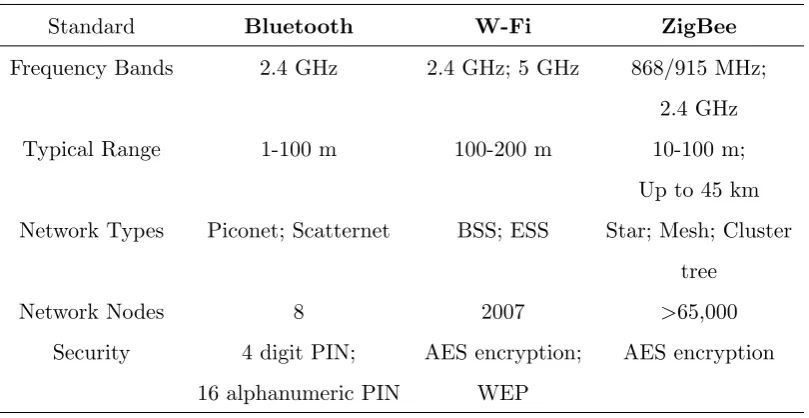
3.5
Evaluation
Provided in Table 3.3 are the primary characteristics distinguished between the three
wireless communication standards that have been looked at. In conclusion, comparing
the three wireless standards with each other, it can be seen that the ZigBee standard
exceeds the other standards in a variety of categories.
Within the Operating Frequencies there are two options for ZigBee, these being in the
area of 915 MHz and also 2.4 GHz. With the availability of the lower frequency band,
915 MHz, it is theoretically possible to be able to reach a distance much farther than
the other standards that make use of frequencies 2.4 GHz and over. If necessary, with
ZigBee there also exists an option for the use of 2.4 GHz similar to the other standards
in the case where 915 MHz frequencies may not be usable.
As mentioned above, ZigBee is capable of reaching a farther distance than the other
standards with the availability of the lower frequency band, with Digi International
stating in the manuals for their XBee ZigBee module that they are capable of reaching
distances up to potentially 45 km with the use of a high-gain antenna. Due to the
requirement set forth of a minimum range for the DataNodes to communicate over,
this is the only standard that is capable of reaching any distance beyond 5 kilometres,
where the other standards usually reach distances around 100 to 200 metres.
capabil-3.5 Evaluation
31
ities with, at best, meshing technology. Whereas each of the standards discussed have
capable wireless routing, the only standard listed with the ability to do a mesh
net-work was the ZigBee standard, also with the capability of having up to and potentially
beyond 65,000 nodes all connected together in the same network.
In the category of Security, each of the wireless standards were equivalent in their
protection, each offering secure encryption.
It is because of these reasons that ZigBee stands out as the most appropriate and
appli-cable wireless communication interface for implementing into the DataNode systems,
3.6 Chapter Summary
32
3.6
Chapter Summary
This chapter has gone through three primary technologies used to achieve wireless
com-munication, looking at certain topics for each wireless interface. Using the information
gathered, an evaluation was put forth over the standards investigated, with the most
Chapter 4
Methodology
4.1
Chapter Overview
This chapter will be outlining and discussing various aspects of the development
method-ology for conducting this project. This includes a brief overview of the methodmethod-ology,
followed by a more in-depth analysis of each of the tasks that will be undertaken over
the course of the project. Following this will be a brief analysis of the resources that
will be required during the project as well as some of the potential consequential effects
and risks that are associated with the project. Included at the end of this chapter is a
diagram of the project’s timeline.
4.2
Development Methodology
The first step for this Project is to undertake a basic requirements analysis to clarify
what each of the specific requirements for the intended end-product are, to provide a
criteria to follow in the research and development within this project.
Following the requirements analysis is an identification of the various different use-cases
that are present in the intended end-product and to develop a specification that will
be suitable to use as both an investigative and decision tool.
4.3 Task Analysis
34
currently available will be identified, followed by conducting a comprehensive literature
review into each of the wireless solutions. This is to firstly determine if such a project
has already been done and to ensure that the wheel is not being reinvented, and to see
if there is any documentation available to assist with the development of this project..
Once a suitable amount of research has been conducted, the results found will then have
the previously developed specification applied to it in order to come to an informed
and well-suited conclusion as to what the best direction to take is.
After the wireless solution has been chosen, different hardware and protocol options
within the chosen wireless interface will be investigated to determine the most
appro-priate hardware choice to go with, taking into consideration the requirements analysis
and other criteria throughout the process.
<