Modelling helical screw piles in
soft clay and design implications
j1 Samuel A. StanierResearch Associate, Centre for Offshore Foundation Systems, University of Western Australia, Australia
j2 Jonathan A. Black
Lecturer, Department of Civil and Structural Engineering, University of Sheffield, UK
j3 Charles C. Hird
Formerly Reader, Department of Civil and Structural Engineering, University of Sheffield, UK
j1 j2 j3
Helical screw piles are a popular solution for relatively low-capacity, removable or recyclable foundations supporting road and rail signage or similar light structures. When specifying a helical screw pile, a designer must choose the active length and the helical plate spacing ratio, which are governed by the number, spacing and size of the individual helices. This paper presents an investigation using transparent synthetic soil and particle image velocimetry to observe the failure of helical screw piles with helical plate spacing ratios of 1.5–3 and active lengths up to three times the diameter. For the geometries and properties examined, capacity is shown to be a function of active length and the dominant failure mechanism is characterised by the formation of a cylindrical failure surface. A simple analytical model is developed and used to assess the impact of different design methodologies on immediate displacements under loading. A traditional ‘permissible stress’ method is shown to be conservative, whereas modern ‘partial factor’ methods are more economical and lead to greater immediate displacements for a given design load. Designers using modern ‘partial factor’ approaches, such as Eurocode 7, might benefit from specifying a helical plate spacing ratio of less than 1.5 to maximise the stiffness of the response to axial loading and minimise the immediate displacements experienced upon application of working loads.
Notation
cv coefficient of consolidation
D diameter
D50 mass median particle diameter
F factor of safety
Fd design action
Fk characteristic action
FkG characteristic load
g gravitational acceleration
H embedment depth
Heff effective shaft length
k shear strength gradient
La active length
Nc bearing capacity factor
Ncu uplift capacity factor
p helical plate pitch
Qbase compressive capacity of lowermost helical plate
Qc compressive capacity
Qcd compressive design capacity
Qd design capacity
Qshaft shaft capacity
Qshear cylindrical shear surface capacity
Qt tensile capacity
Qtd tensile design capacity
Quplift uplift capacity of uppermost helical plate
Rb base resistance
Rcal calculated resistance Rcal base calculated base resistance Rcal shaft calculated shaft resistance Rcal shear calculated shear resistance Rcal uplift calculated uplift resistance Rc cal calculated compressive resistance
Rcd design compressive resistance
Rtd design tensile resistance
Rd design resistance
Rk characteristic resistance
Rs shaft resistance
Rst tensile resistance
Rt total resistance
Rt cal calculated tensile resistance
Sf correction factor
s helical plate spacing
su0 surface shear strength
su-base shear strength at depth of lowermost helical plate su-uplift shear strength at depth of uppermost helical plate
V dimensionless velocity
v velocity
x ineffective shaft length parameter
Æs–p alpha parameter for soil–pile interaction Æs–s alpha parameter for soil–soil interaction ªb base resistance partial factor
ªF action partial factor
ªR resistance partial factor ªs shaft resistance partial factor
ªsh cylindrical shear resistance partial factor ªsu undrained shear strength partial factor
ªu uplift resistance partial factor
displacement
correlation factor
rpx standard error
1. Introduction
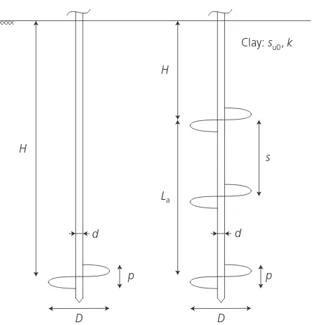
[image:2.595.310.534.133.364.2]Previous research on the behaviour of helical screw piles in clay soils has focused predominantly on the behaviour of multi-helix screw piles loaded in either axial compression or tension with varying embedment depth,H(relative to the mid-depth of the uppermost helical plate), helical plate diameter, D, helical plate spacing ratio, s/D, and active length, La, as defined in
Figure 1.
Raoet al.(1991) investigated the impact of the number of helical plates on ultimate capacity in clay using model helical screw piles of 75 mm diameter in a bed of compacted clay. The number of helical plates over a fixed length of helical screw pile significantly affected the capacity and stiffness of the response of the piles, leading to the conclusion that maximum capacity was attained whens/Dwas between 1.0 and 1.5. Based upon post-test analysis of exhumed model piles, the authors attributed the variation in performance to changes in failure mechanism caused by the different plate configurations. Piles with s/D,1.5 ex-tracted intact cylinders of soil between the helical plates, whereas piles with s/D.1.5 tended to collect isolated plugs of soil around each helix. This suggested that failure mechanisms for the different configurations of pile ranged from cylindrical shear to individual plate bearing capacity.
Based upon these observations Rao et al. (1991) proposed simple design equations for the ultimate capacity of helical screw piles loaded in either compression or tension, assuming a cylindrical failure surface between the uppermost and lowermost
helical plate. Predictions of the capacities in the model tests made using these design equations were reasonable for s/Dover the range of 1.0–1.5 (within 10%), but led to over-prediction of capacity for piles with s/D.1.5 (up to 40% over-prediction). Recognising that the assumed cylindrical failure mechanism might not be applicable for s/D.1.5, Rao et al. (1993) introduced a correction factor, Sf, dependent on s/D. The Sf
factor was determined empirically using the experimental results reported in Rao et al. (1991) and compared favourably to limited field data (three tests) from full-scale pullout tests reported by Mooneyet al.(1985). It should be noted that, as the clay used by Rao et al.(1991) was remoulded, it probably had a very low sensitivity, both in absolute terms and relative to that of natural clay deposits.
Lutenegger (2009) presented field test data on the uplift capacity of helical screw piles in clay with comparison to estimated capacities using cylindrical failure and individual plate bearing mechanisms. The study implied that the failure mechanism assumed in design (cylindrical failure or individual plate bearing) ought to depend ons/D.
Recent numerical work by Merifield (2011) used small strain finite-element simulations of the ultimate uplift capacity of wished-in-place, deeply embedded, horizontal, circular plates at varying s/Dto show that the mechanism changed from cylind-rical shear to individual plate bearing failure at s/D¼1.58. However, it is noteworthy that these (axisymmetric) analyses did not consider the impact of the pile shaft and the installation process on ultimate capacity or model realistically the true (non-axisymmetric) geometry of the helical plates.
D d
p H
La
s
Clay:su0,k
D d
p H
The s/Dof helical screw piles used in practice can range from 1.0 to as much as 6.0. Thus, to allow accurate prediction of pile performance, it is critical that the correct failure mechanism is identified for a range of s/D. Research methods aimed at enabling prediction of the transition referred to above all have limitations. While current best estimates of the transitional s/D
arising from numerical analysis neglect the impact of the shaft resistance, installation process and complex geometry, the latter two factors are also neglected in potential physical modelling using a plane strain or axisymmetric protocol of testing with natural soil against a transparent window (White et al., 2003). Comprehensive full-scale testing is expensive and difficult due to natural variability in ground conditions and limited ability to capture ground displacements from which to deduce failure modes. The development of transparent media, consisting of silica particles and a fluid of matched refractive index, as an analogue for soil (e.g. Iskanderet al., 1994), has allowed the use of laser-aided particle image velocimetry (PIV) to measure internal deformations in physical models. This technique pro-vides scope to increase the understanding of soil–structure interactions. For example, Hird et al. (2008) and Ni et al.
(2010) report the use of clay-like transparent soil, formed using precipitated silica and seeded with reflective particles, to observe displacements around continuous augers and press-in piles re-spectively. A significant drawback with these two investigations was that model size was limited by imperfect transparency of the soil, introducing boundary effects. Hird and Stanier (2010) reported that using fumed rather than precipitated silica (follow-ing McKelvey et al., 2004) in conjunction with the laser-aided PIV technique allowed larger models to be used, thereby reducing boundary effects. Later Stanieret al. (2012) proposed a photogrammetric correction framework to improve the reliability of the PIV measurements made in their transparent soil, along-side an example analysis of the failure mechanism of a double-helix screw pile loaded in tension.
This paper reports a series of tests on small-scale physical models of helical screw piles, using the material and analysis techniques described by Hird and Stanier (2010) and Stanier et al. (2012), that were devised to investigate the failure mechan-isms over a range of s/D ratios. This investigation addresses limitations of previous work on helical screw pile failure mechanisms by providing internal displacement measurements, obtained using transparent soil in conjunction with PIV. The rotational installation process was modelled faithfully using a model pile with a realistic geometry. A simple calculation model to predict the capacity of helical screw piles is proposed based on the observed ultimate limit state (ULS) failure modes from the model tests and the performance of a range of design methodologies, including traditional ‘permissible stress’ and Eurocode 7 approaches, is also assessed. The impact of the design methodology on immediate settlements under working loads is then considered, highlighting the impact of modern, more economical, partial factor based design procedures as opposed to the traditional approach.
2. Physical modelling
2.1 Apparatus
The apparatus used in this investigation was described in detail by Stanier et al. (2012). In brief, the tests were performed in an aluminium chamber with internal dimensions of 200 mm by 200 mm in plan and 500 mm in depth. Transparent acrylic windows were provided on two adjacent sides to allow transmission of a laser light sheet through the centre of the soil sample and recording of digital images of the highlighted plane. A 1-W argon-ion air-cooled laser was used to produce a 0.95 mm diameter laser beam of 457–514 nm wavelength, which was passed through a top-hat beam shaper prism to produce the laser light sheet with approximately uniform intensity. Digital images of the highlighted plane were captured using a digital single lens reflex camera (Pentax K10-D) mounted on a tripod placed perpendicular to the front viewing window. The images were stored on an SD memory card (8GB SanDisk Extreme III), with a maximum data transfer speed of 20 MB/s, which facilitated continuous capture of ten megapixel images at a rate of 3.3 frames/s. Two detachable control point panels, each consisting of a row of eight direct current powered red light-emitting diodes (LEDs) spaced at 20 mm, were fixed to the front of the test chamber to provide a reference for photogrammetric correction of PIV measurements following Stanieret al. (2012).
The model helical screw piles had helical plates of 20 mm diameter, a shaft of 5 mm diameter, a helical plate pitch, p, of 5 mm and a plate thickness of 1 mm (see Figure 1 for a schematic diagram of the geometry). The termination of the shaft was a 458 cone to aid keying during installation. During installation the rate of penetration was such that the pile penetrated vertically by the distance of the pitch for each rotation to minimise installation disturbance. The model piles were modular, with separable helical plates and shaft sections, enabling four geometric configurations of model pile to be assembled as summarised in Table 1. The model screw piles were installed and tested using an actuator providing control of vertical displacement and rotation. This was capable of exerting
Test No. plates Loading La: mm s/D H/D
C1 1 Compression 0.0 1 7
C2–30 2 Compression 30.0 1.5 5.5
C2–60 2 Compression 60.0 3.0 4
C3 3 Compression 60.0 1.5 4
T1 1 Tension 0.0 1 7
T2–30 2 Tension 30.0 1.5 5.5
T2–60 2 Tension 60.0 3.0 4
[image:3.595.314.553.637.759.2]T3 3 Tension 60.0 1.5 4
an axial force of 1 kN and a torque of 1 N m, over an axial range of travel of 300 mm. However, although axial force was measured during load testing using a suitable transducer (Omega LCM213–200N), there was no facility to measure torque or axial force during installation.
2.2 Transparent soil
The transparent soil used in this investigation consisted of 6% fumed amorphous silica aggregates (Lehane and Gill, 2004; McKelvey et al., 2004) and 94% pore fluid. This fluid was a blend of paraffinic solvent (N-paraffin C10-13 supplied by Aztec Oils, Chesterfield, UK) and white oil (Baylube WOM 15 supplied by Bayford Oils, Leeds, UK) mixed to volumetric proportions of 77:23 and giving a refractive index matched to the silica aggregates at 208C. The process used to optimise the transparency of the soil was described in detail by Stanier (2011).
To provide the distinctive image texture required by PIV (White
et al., 2003), Timiron powder (Niet al., 2010) was added in the proportion of 0.02% by mass compared to the fumed silica powder. Timiron powder consists of platy mica particles (D50 of 10–60ìm) coated with titanium oxide. When illuminated using a laser light sheet, the particles provide contrast with the back-ground of the field of view enabling precise PIV displacement measurements to be made (Hird and Stanier, 2010).
2.3 Model preparation
Following thorough mixing of the transparent soil, it was subjected to vacuum until all air was removed. The rearward 52.5% of the sample was seeded with Timiron powder, whereas the front 47.5% volume was left unseeded so as to preserve maximum clarity on the measurement plane at the centre of the chamber. The seeded and unseeded soil was separated during sample pouring using an aluminium sheet divider following Niet al.(2010), after which the sheet was removed to allow consolida-tion in stages to a vertical effective stress of 100 kPa using a pneumatic piston. Top and bottom drainage was provided and the piston was sealed using a 4 mm cylindrical O-ring, mitred and bonded at 458 to permit right-angle fitment in the chamber corners.
A potentiometric draw-wire transducer was used to monitor consolidation settlements, allowing consolidation properties to be derived for each sample. The mean values for the final effective stress increment were as follows, with the standard deviations given in brackets: the coefficient of consolidation,cv, was 4 m2/
year (¼0.56) and the coefficient of compressibility was 43103m2/kN (¼1.323104). The low standard deviations
indicate that the sample preparation process was acceptably repeatable. The consolidation behaviour is comparable to that of soft, normally consolidated alluvial clays with compressibility characteristics comparable to those of very highly organic clays and peats (Gill, 1999).
2.4 Testing
Each model pile was installed to a depth of 7D or 140 mm, measured from the mid-depth of the lowermost helical plate. Depending on the pile configuration the depth measured to the mid-depth of the uppermost helix (for piles with more than one helix) was between 80 and 110 mm, which represents a deeply installed condition (H/D>4, see Table 1). Following insertion a period of 24 h was allowed to facilitate equalisation of installa-tion induced excess pore pressures.
Following Finnie and Randolph (1994) an undrained rate of loading was achieved by adopting a vertical drive speed (v) of 0.2 mm/s, yielding a dimensionless velocity (V¼vD/cv) of more
than 30 given the average cv of 4 m2/year and helical plate
diameter of 20 mm.
Tests were conducted in a darkroom and the central plane of the model was illuminated using the laser light sheet. The LED control point panels were energised and the digital camera was aligned using a suitable target so that the charge coupled device (CCD) within the camera was coplanar with the target plane. Digital images were captured at the maximum rate of 3.3 frames/s for the duration of the test, with camera settings of ISO 100, F10.0 aperture and exposure time of one-tenth of a second. These settings were found to provide the most precise PIV measurements (Stanier, 2011). A series of up to 70 images was recorded during mobilisation of the ULS for each pile.
2.5 Post-test sample properties
A series of 38 mm diameter undrained unconsolidated (UU) triaxial tests were performed on specimens extracted from a consolidated model test sample using thin-walled sampling tubes. The undrained stiffness (Eu) and undrained shear strength (su)
parameters derived from these tests were approximately 535 kPa and 16 kPa respectively. These parameters were taken as repre-sentative of those at the mid-height of the consolidated model test sample.
In addition to the UU triaxial tests, hand vane shear measure-ments were taken using a 33 mm diameter hand vane with an aspect ratio (length/diameter) of 2 at one-third and two-thirds of the sample depth. To these measurements (assuming linearly varying shear strength with depth) mean, upper and lower bound shear strength profiles were fitted yielding surface shear strengths, su0, and gradients, k, given in Table 2. The reducing
shear strength with depth, commonly observed in 1g model
Parameter Maximum Mean Minimum
su0: kPa 20.4 19.4 18.6
k: kPa/m 30 30 30
testing with overconsolidated clay, is likely to have been caused by sidewall friction within the test chamber reducing the effec-tive stress with depth during the consolidation process. However, the dimensionless gradient kD=su0 is very small at 0.032,
indicating high sample uniformity relative to the helical plate size and surface shear strength. The sensitivity of the soil, as measured with the vane, was about 2 but the original strength was substantially recovered after 24 h. Therefore, as far as installation effects are concerned, the soil may be regarded as insensitive, although installation may still have influenced subse-quent behaviour.
2.6 Data processing
Particle image velocimetry analysis was conducted on the digital images recorded during helical pile loading using GeoPIV (White
et al., 2003). The analyses presented in this paper were conducted using a 50-pixel patch size, which yielded an average standard error, rpx, of 0.012 pixels (Hird and Stanier, 2010). This is
comparable to the upper bound precision error estimator proposed by White et al. (2003), confirming that Timiron powder illumi-nated by the laser light sheet provided adequate texture for precise PIV analysis. Photogrammetric errors (internal camera lens induced distortions, external camera-control plane move-ments, scale correction and control-target plane non-coplanarity errors) were mitigated following the procedure proposed by Stanieret al.(2012). This process was demonstrated to provide a standard deviation of the errors of 51.5ìm on average and a precision of 5–20ìm, which compare favourably to the system errors quoted by White et al. (2003) for a plane strain test configuration. From the displacement fields computed using GeoPIV, the engineering shear strain fields were derived using the rotating reference frame method outlined in White and Bolton (2004), with these plots being used to interpret the failure mode for each pile configuration.
3. Results
[image:5.595.320.549.138.340.2]3.1 Performance
Figure 2 presents the load–displacement response of the four helical pile geometries, loaded in both compression and tension. There was no facility to release installation-induced axial forces after the completion of installation; hence the displacement required to counter the residual force has been offset. This correction was necessary to allow clear comparison of the impact of the geometry of the piles on their performance. Two repeat tests were performed and yielded discrepancies in force at a given displacement that were never more than 6% and were less than 3% on average, indicating acceptable repeat-ability.
Figure 2 shows that the overall compressive and tensile perform-ance of each pile configuration is almost identical, due to the deep embedment (H/D>4). An increased stiffness response is observed with an increasing number of helices; however, the addition of a third helical plate in C3 and T3 when compared to
C2–60 and T2–60 respectively (thus reducing s/Dfrom 3.0 to 1.5 while maintaining the active length, La) generated no
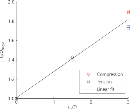
additional ultimate capacity. Figure 3 is a plot of the active length normalised by helical plate diameter against the ultimate capacity divided by the capacity of the corresponding single pile test in compression or tension as appropriate. The ultimate capacity is taken to be the force mobilised by a displacement of 5 mm. The linear best fit shows that ultimate capacity increases in proportion to active length,La:It should be noted that in natural, structured
clay deposits the displacements at the ULS relative to the plate diameter would be expected to be smaller than those seen in the model tests.
⫺5 ⫺4 ⫺3 ⫺2 ⫺1 0 1 2 3 4 5 ⫺150 ⫺125 ⫺100 ⫺75 ⫺50 ⫺25 0 25 50 75 100 125 150
Displacement, : mmδ
Axial load,
: N
Q
[image:5.595.325.547.567.753.2]C1 C2–30 C2 60– C3 T1 T2 30– T2 60– T3 Compression Tension
Figure 2.Performance of helical screw piles in transparent soil representing a soft clay deposit
0 1 2 3
1·0 1·2 1·4 1·6 1·8 2·0
La/D
Q Q
/
single
Compression Tension Linear fit
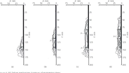
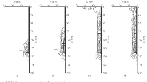
3.2 Displacement and shear strain fields at ULS
Figure 4 and Figure 5 present the engineering shear strain fields for a 1 mm increment of additional displacement at the ULS for the four configurations of helical screw pile loaded in compres-sion and tencompres-sion respectively. For the single-helix pile (C1 and T1) Figure 4(a) and Figure 5(a) indicate concentrated shearing at the outer edge of the helical plate, which diminishes rapidly with radial distance from the pile. There is some skew in the direction of the mechanisms, which is probably a product of the direction of pile displacement during loading. Additional helical plates cause the failure mode to extend between the outer edges of the helical plates. This is consistent with the proposition of Raoet al.
(1991, 1993) that a cylindrical failure mechanism occurs and is clearly apparent for all the multi-helix configurations tested here. This is true regardless of whether the loading applied to the pile was compressive or tensile, or whether s/D was 1.5 or 3.0. However, this is contrary to the findings of the numerical analyses conducted by Merifield (2011), where s/D¼3.0 generated in-dividual bearing capacity failure mechanisms at each of the plates. This could possibly be a consequence of the rotational installation process or the presence of the pile shaft, neither of which was modelled by Merifield (2011).
Comparison of tests C2–30 and C3 or of tests T2–30 and T3 using figure parts (b) and (d) in Figure 4 or Figure 5, wheres/D
was 1.5 and La was either 30 mm or 60 mm, provides
mechan-istic evidence for the trend seen in Figure 3. The ultimate capacity is simply related to the length of shear band being mobilised along the pile. Comparison of the failure mechanisms for tests C2–60 and C3 or for tests T2–60 and T3 using figure parts (c) and (d) in Figure 4 or Figure 5, where La was 60 mm and s/Dwas either 3.0 or 1.5, shows that s/Dhas no significant impact. For both pile configurations, the shear band extends between the uppermost and lowermost helical plates. Therefore the length of the shear band and thus the ultimate capacity is governed only by La:These observations confirm experimentally
the prevalence of a cylindrical failure mechanism as hypothe-sised by Rao et al. (1991, 1993) for helical screw piles in clay soils with s/D<3.0.
The shear bands in tests T2–60 and T3 propagated to the surface of the model to some degree. This perhaps provides a reason for the slightly reduced ultimate capacity of the tensile tests with La
of 60 mm compared to the compressive counterparts, as evident in Figure 3.
It should be noted that the discontinuous cylindrical shear bands seen in Figure 4(b) and Figure 5(c) are the product of implausible PIV computations, otherwise known as ‘wild vectors’ caused by locally poor texture in the recorded images. These were manually
X: mm
Y
: mm
X: mm
Y
: mm
X: mm
Y : mm 0 25 50 75 0 25 50 75 100 125 150 175 200
X: mm
Y : mm 1 1 5 10 2·5 10 5 1 5 0 25 50 75 0 25 50 75 100 125 150 175 200 1 1 5 10 10 25 10 0 25 50 75 0 25 50 75 100 125 150 175 200 1 1 2·5 5 5 10 10 25 25 0 25 50 75 0 25 50 75 100 125 150 175 200 1 1 1 2·5 2·5 5 10 10 10 5 25 5 5
[image:6.595.46.535.459.737.2](a) (b) (c) (d)
removed from the output dataset, leading to erroneously discon-tinuous contours of shear strain.
4. Impact on design practice
4.1 Analytical calculation model
Following Rao et al. (1991), simple net capacity estimates are obtained by assuming that the total capacity (Q) is composed of the following components when loaded in compression (Qc) or
tension (Qt)
Qc¼QbaseþQshearþQshaft 1:
Qt¼QupliftþQshearþQshaft 2:
where Qbase or Quplift is the bearing or uplift capacity of the
projected area of the lowermost or uppermost helical plate,Qshear
is the capacity of the cylindrical failure andQshaftis the capacity
mobilised by shaft adhesion. By integrating where necessary to account for the linearly varying undrained shear strength with depth apparent in the physical models, the following expressions are derived in terms of the surface strength, su0 and the shear strength gradient,k
Qbase¼ D
2
4
Ncsu-base
¼ D
2
4
Nc½su0þk(HþLa)
3:
Quplift¼ (D
2d2)
4
Ncusu-uplift
¼ (D
2d2)
4
Ncu(su0þkH)
4:
Qshear¼ÆssD
kL2a
2 þ
2kHLa
2 þsu0La
5:
Qshaft¼Æspd su0Heffþ
kH2 2 0 6:
wheredand Dare the shaft and helical plate diameters respec-tively, Nc and Ncu are the bearing and uplift capacity factors, X: mm Y : mm X: mm Y : mm X: mm Y : mm 0 25 50 75 0 25 50 75 100 125 150 175 200 X: mm Y : mm 1 1 2·5 2·5 5 5 10 10 25 0 25 50 75 0 25 50 75 100 125 150 175 200 1 1 1 2·5 2·5 5 5 10 10 25 1 1 5 0 25 50 75 0 25 50 75 100 125 150 175 200 1 1 2·5 2·5 5 5 12·5 10 10 10 10 5 10 2·5 0 25 50 75 0 25 50 75 100 125 150 175 200 1 1 1 2·5 2·5 5 5 5 10 10 5 1 1 1
[image:7.595.66.542.136.402.2](a) (b) (c) (d)
which are assumed to be equal to 9 for deep embedment following Raoet al.(1991),His the embedment depth measured from the soil surface to the mid-depth of the uppermost helical plate,Lais the active length of the pile,Æs–sis the friction factor
for soil–soil shearing andÆs–p is the friction factor for soil–pile
shearing. Both of these friction factors were assumed to be unity owing to the low sensitivity of the transparent soil limiting strength loss caused by installation and, forÆs–s, additionally to
the expectation that the value of alpha for such an interface will be high for low-strength soils (Merifield, 2011). However, the incorporation ofÆs–s and Æs–p provides a facility to account for
installation effects in more sensitive soils. For exampleÆs–s and Æs–pmight be assumed to be equal to the inverse of the sensitivity
for a sensitive soil.
The correction factor, Sf, proposed by Rao et al. (1993) to
account for the reduced capacity observed with increasing s/D
has been omitted, as in this investigation no significant bias with
s/D was observed. Heff is the assumed effective shaft length,
which is a reduced length over which shaft adhesion is mobilised during loading where
Heff ¼HxD
7:
and xDis the ineffective shaft length. This was varied between 1.4Dand 2.3Din the investigation presented by Raoet al.(1993) with limited justification. However, in the present investigation it was defined by examining the incremental vertical displacements computed in the PIV analyses. Differential displacements were observed over a comparatively greater shaft length for the compressive tests compared to the tensile counterparts. Hencex
[image:8.595.296.538.374.464.2]was estimated as 1.0 for piles loaded in compression and 2.0 for piles loaded in tension.
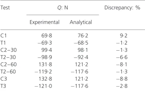
Table 3 summarises the experimental and estimated capacities calculated using the analytical model and the corresponding
discrepancy as a percentage of the experimental capacity at the ULS (taken at¼ 5 mm). All discrepancies are less than 10%, with an average under-prediction of 2.75%. Therefore the calculation model is conservative, yet reasonably accurate.
4.2 Impact of various design methodologies
Using this simple cylindrical shear calculation model various design methodologies, including a traditional ‘permissible stress’ approach, a simple bearing/uplift capacity in reserve approach and modern partial factor Eurocode 7 approaches, were used to investigate the variability of calculated design loads and immedi-ate displacements inferred from the experimental responses.
4.2.1 Permissible stress
The traditional ‘permissible stress’ approach uses a global safety factor,F, to reduce the ultimate capacity to generate an allowable design capacity. By incorporating Equations 3–6, the design load in compression (Qcd) and tension (Qtd) were derived as follows
Qcd¼
(QbaseþQshearþQshaft)
F 8:
Qtd¼
(QupliftþQshearþQshaft)
F 9:
The value forFis taken as 3 in this analysis.
4.2.2 Base/uplift capacity in reserve
An alternative method of calculating design capacities might be to keep the contribution of either the bearing or uplift capacity of the lowermost or uppermost helical plate in reserve. The potential validity for this methodology relies on the commonly accepted fact that piles mobilise shaft capacity more rapidly than base capacity (Tomlinson and Woodward, 2008). Hence, the design capacities, Qcd and Qtd were derived by disregarding the uplift
and base capacities as follows
Qd¼Qcd¼Qtd¼(QshearþQshaft) 10:
4.2.3 Eurocode 7
Eurocode 7 defines the ULS adequacy by comparing design actions,Fd, with design resistances,Rd
Fd <Rd
11:
where adequacy is assumed if the above statement is true. Fd is equal to
Test Q: N Discrepancy: %
Experimental Analytical
C1 69.8 76.2 9.2
T1 69.3 68.5 1.2
C2–30 99.4 98.1 1.3
T2–30 98.9 92.4 6.6
C2–60 131.8 121.2 8.1
T2–60 119.2 117.6 1.3
C3 132.8 121.2 8.8
[image:8.595.39.278.598.749.2]T3 121.0 117.6 2.8
Fd¼
X FkªF
12:
whereFk are the characteristic actions andªFare the appropriate
partial factors which are summarised in Table A.3 of Annex A of EN 1997-1 (BSI, 1997). The design resistance Rd for the pile is obtained using
Rd¼
XRk
ªR
13:
where Rk are the characteristic resistances and ªR are the
appropriate partial factors for each component of resistance, which are summarised for base resistanceRb, shaft resistanceRs,
total resistanceRt and tensile resistanceRst for driven, bored and
CFA piles in Tables A.6–8 of Annex A of EN 1997-1.
The characteristic resistanceRkis calculated using
Rk¼
Rcal
14:
whereRcal is the calculated resistance, governed by the assumed
calculation model, and is the appropriate correlation factor, dependent on the source and amount of data used to obtain the calculated resistances. Tables A.9–11 of Annex A of EN 1997-1 summarise the correlation factors for static pile load tests, ground tests and dynamic tests. To satisfy Eurocode 7 both mean and minimum resistances need to be assessed, with the lower characteristic resistance,Rk, being carried forward in the calcula-tion of design resistance,Rd:For the calculations presented here,
each pair of vane tests, taken at different depths but the same location, are assumed to constitute a single measurement of the strength profile with depth and are considered ground tests. As four pairs of vane tests were performed in each of the ten samples tested (eight model tests and two repeat model tests), 40 measure-ments were taken in total and appropriate values for were selected on this basis.
The calculated resistanceRcalis determined using either Equation
15 or 16, where Rcal base is the base resistance, Rcal uplift is the
uplift resistance, Rcal shear is the cylindrical failure surface shear
resistance andRcal shaftis the shaft resistance.
Rc cal ¼(Rcal baseþRcal shearþRcal shaft)
15:
Rt cal¼(Rcal upliftþRcal shearþRcal shaft)
16:
The calculation model used to derive the calculated resistance,
Rcal, must incorporate the appropriate partial factors for material
properties, ªM, which are summarised in Table A.4 of Annex A
of EN 1997-1.
Given that the calculation model describes the net capacity of a helical screw pile under undrained loading in clay, the only relevant partial factor on material properties is ªsu, which is incorporated as follows
Rcal base¼
D2
4
Nc
su0
ªsu
þk(HþLa)
17:
Rcal uplift¼
(D2d2)
4
Ncu
su0
ªsu
þkH
18:
Rcal shear ¼ÆssD
kL2a
2 þ
2kHLa
2 þ
su0
ªsu
La
" #
19:
Rcal shaft¼Æspd
su0
ªsu
Heffþ
kH2
2
" #
0
( )
20:
In these calculations the mean and minimum strength profiles given in Table 2 were assumed.
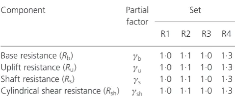
The resistance partial factor sets given by Eurocode 7 do not currently cater for helical screw piles. Therefore, suitable partial factors need to be proposed for each resistance component
(Rkbase, Rkuplift, Rkshear and Rkshaft). In this paper it is assumed
that the shaft friction and base resistance mobilised by a helical screw pile is most similar in nature to that mobilised by a driven pile. Tables A.6–8 of Annex A of EN 1997-1 demonstrate that the impact of this assumption is limited, since there is only a small impact upon the values of sets R1 and R4 and no impact upon sets R2 and R3. Given that the model piles tested here were deeply installed andNcuis assumed to equalNc, the partial factors
for the uplift resistance, referred to here asªu, as a first estimate
might be assumed to equal those for the base resistance, that is ªu¼ªb:The development of a shear band at the outer edges of
the helical plates over the active length is thought to be mechanically similar to the development of shearing resistance along the effective shaft length,Heff:Thusªsh is taken as equal
[image:9.595.311.557.242.473.2]toªs:A summary of the assumed partial factors is presented in
Carrying forward the minimum characteristic resistance and incorporating the appropriate partial factors from Table 4 leads to the compressive (Rcd) and tensile (Rtd) design resistances being
computed as
Rcd¼
Rkbase
ªb
þ Rkshear
ªsh
þ Rkshaft
ªs
21:
Rtd¼
Rkuplift
ªu
þ Rkshear
ªsh
þ Rkshaft
ªs
22:
To satisfy different member nations, Eurocode 7 allows a number
of different design approaches (DAs), which employ different partial factor sets and are summarised in Table 5. For DA3 the action partial factors can be taken from either set A1 or A2, depending on whether the action in question is a structural action or a geotechnical action (Bond and Harris, 2008). Here, the capacities calculated for the helical screw piles are net capacities. Thus all actions are considered to be structural and set A1 is used.
Assuming an adequacy factor of unity the design force, Fd, is
equal to the design resistance, Rd (Rcd or Rtd). Thus the
characteristic load, FkG, is calculated by dividing Rd by the
appropriate partial factor,ªG, taken from Table A.3 of Annex A
of EN 1997-1
FkG ¼ Rd
ªG
23:
This can be regarded as equivalent to the design loads (Qcd or Qtd) derived using the ‘permissible stress’ and ‘uplift/base
capacity in reserve’ methods, allowing comparison of the maxi-mum safe capacity calculated using each of the design method-ologies.
4.3 Comparison of design methodologies
[image:10.595.39.279.141.241.2]The design loads calculated using the ‘permissible stress’, ‘uplift/ base capacity in reserve’ and Eurocode 7 DAs are summarised in Table 6 with compressive loading denoted by positive values. The
Component Partial
factor
Set
R1 R2 R3 R4
Base resistance (Rb) ªb 1.0 1.1 1.0 1.3
Uplift resistance (Ru) ªu 1.0 1.1 1.0 1.3
Shaft resistance (Rs) ªs 1.0 1.1 1.0 1.3
[image:10.595.39.281.357.445.2]Cylindrical shear resistance (Rsh) ªsh 1.0 1.1 1.0 1.3
Table 4.Partial factors for resistances generated by helical screw piles proposed by the authors
Design approach DA1 DA2 DA3
Combination 1 Combination 2
Partial factor sets A1 + M1 + R1 A2 + M1 + R4 A1 + R2 + M1 A1orA2 + M2 + R3
Primary variable Actions Resistances Actions and resistances Actions and material properties
Table 5.Eurocode 7 design approach partial factor sets and primary variables, after Bond and Harris (2008)
Methodology QdFkG: N
C1 C2–30 C2–60 C3 T1 T2–30 T2–60 T3
Permissible stress 25.4 32.7 40.4 40.4 22.8 30.8 39.2 39.2
Base/uplift in reserve 33.2 55.1 78.2 78.2 28.1 49.7 72.6 72.6
EC 7 – DA1 comb. 1 45.2 58.1 71.8 71.8 44.3 59.9 76.3 76.3
EC7 – DA1 comb. 2 46.9 60.3 74.6 74.6 46.1 62.2 79.3 79.3
EC7 – DA2 41.1 52.8 65.3 65.3 40.3 54.5 69.4 69.4
EC7 – DA3 29.7 38.0 47.0 47.0 29.0 39.5 50.8 50.8
[image:10.595.39.544.489.772.2]Range 21.5 27.7 37.8 37.8 23.2 31.4 40.1 40.1
[image:10.595.39.539.619.760.2]range in calculated capacities for any given pile configuration is similar to the minimum calculated capacity, indicating that there is significant variation in the calculated design capacity when different design methodologies are employed.
Figure 6 is a plot of ‘overdesign’ factors derived by dividing the experimental capacity by the design capacity. This shows that the ‘permissible stress’ method is consistently the most conservative methodology, with Eurocode 7 DA3 second. The ‘uplift/base capacity in reserve’ method and Eurocode 7 DA1, combinations 1 and 2, and DA2 are, in contrast, consistently less conservative. These ‘overdesign’ factors are relatively consistent for all pile geometries for each design methodology, except the ‘uplift/base capacity in reserve’ method. This is due to the fact that, asLa is
[image:11.595.126.493.516.757.2]increased, the proportion of total capacity provided by either the base or uplift capacity reduces and consequently conservatism reduces. This limits the validity of this method as a design approach as it introduces bias withs/D.
Figure 7 is a plot of the displacement that would have been induced in the model tests by application of the design loads summarised in Table 6, showing significant scatter in the inferred immediate displacements. As expected the ‘permissible stress’ method, which was the most conservative, leads to the smallest immediate displacements, whereas Eurocode 7 DA1 combinations 1 and 2 exhibited the largest displacements. This illustrates the importance of the initial stiffness of the load–deflection response of the helical screw piles, which is governed by the helical plate spacing. For example, comparing the extreme cases of the
single-helix (C1/T1) and triple-single-helix (C3/T3) piles, it can be seen that the low stiffness configuration (single helix) is sensitive to small increases in applied load. In contrast, the high stiffness configura-tion (triple helix) is far more tolerant of increases in applied load, which cause much less significant increases in the immediate
Permissible stress
Uplift/base in reserve
EC7 – DA1 Comb. 1
EC7 – DA1 Comb. 2
EC7 – DA2 EC7 – DA3 0
0·5 1·0 1·5 2·0 2·5 3·0 3·5
Design methodology
Experimental/design
C1 C2–30 C2–60 C3 T1 T2–30 T2–60 T3 C1
T3
Figure 6.Experimental/design capacity calculated using various design methodologies
⫺1·5 ⫺1·0 ⫺0·5 0
0·5 1·0 1·5 ⫺100
⫺75 ⫺50 ⫺25 0 25 50 75 100
Permissible stress Uplift/base in reserve EC7–DA1–comb. 1 EC7–DA1–comb. 2 EC7–DA2
EC7 – DA3
C1 C2–30 C2–60 C3 T1 T2–30 T2–60 T3
Displacement, : mmδ
Axial load,
: N
Q
Compression Tension
displacement of the pile. This provides another reason for practi-tioners to prefer helical screw piles with smallers/Dratios (i.e. less than 1.5).
Figure 8 is a graphical summary of the inferred immediate displacement of each pile configuration, expressed as a percent-age of the helical plate diameter. Table 7 gives the standard deviation of the (percentage) immediate displacement for each of the design methodologies, showing that the least conservative design methodologies not only lead to the largest immediate displacements but also the greatest range in inferred displace-ment due to application of a design load. Therefore it is suggested, in particular where Eurocode methods are to be used (which are intentionally less conservative so as to be more economical), that the effect of plate spacing on serviceability is considered.
It may be noted that ifF¼2 rather thanF¼3 had been assumed with the ‘permissible stress’ method, the differences in design capacity and inferred immediate movement as compared with the Eurocode methods DA1 and DA2, although smaller, would have remained.
The inferred immediate displacements in Figure 8 are relatively large. The transparent soil utilised here exhibits similar shear strength to that of soft clays. However, silica-based transparent
soil is less stiff than natural clay (Iskanderet al., 2002), so that a greater shear strain must occur before full strength is mobilised. Therefore, it would be imprudent to extrapolate the immediate displacement estimates given here to problems in real soils at prototype scale. Nevertheless, the observed trends are relevant to practice.
5. Conclusion
Numerous researchers have investigated the failure mechanisms governing helical screw pile capacity over the years, using both experimental and numerical techniques. This paper presents novel
EC7 – DA3 T3
0 1 2 3 4 5 6 7 8
Per
centage displacement: %
C1 C2–30 C2–60 C3 T1 T2–30 T2–60 T3
Permissible stress
Uplift/base in reserve
EC7–DA1 comb. 1
EC7–DA1 comb. 2
EC7–DA2
[image:12.595.300.539.143.240.2]Design methodology C1
Figure 8.Immediate displacement as a percentage of helical plate diameter estimated using design capacities derived using various design methodologies and corresponding load– displacement response from model tests
Methodology Standard deviation: %
Permissible stress 0.29
Base/uplift in reserve 0.72
EC7 – DA1 comb. 1 1.05
EC7 – DA1 comb. 2 1.21
EC7 – DA2 0.88
EC7 – DA3 0.49
[image:12.595.110.472.487.733.2]observations of the failure mechanisms of helical screw piles with a plate spacing ratio, s/D, in the range of 1.5–3.0, by using transparent soil and laser-aided PIV. The shear strain fields derived from the PIV analyses show that a cylindrical failure mechanism is dominant over this range ofs/D. A combination of these mechanistic observations and the accompanying load– displacement measurements shows that the ultimate capacity in compression or tension is primarily a function of the active length of the pile,La:
A simple analytical model based upon that of Raoet al. (1991) but also accounting for linearly varying shear strength with depth has been proposed. This is shown to predict the capacities of the model piles adequately (to within about 10%), although soil disturbance due to pile installation, which could be significant in more sensitive soils, is not taken into account. Using this model, the impact of various design methodologies has been assessed for methods ranging from a traditional ‘permissible stress’ approach to modern ‘partial factor’ methods such as those given by Eurocode 7. In this analysis immediate displacements have been inferred by the calculation of design loads, followed by the back calculation of the corresponding displacement that would have been observed in the model tests had the design loads been applied experimentally. The traditional approach is shown to be more conservative, whereas modern approaches are intentionally more economical and thus lead to greater immediate displace-ments upon application of design loads.
A key point arising from this work is that using more closely spaced helical plates leads to a stiffer response and thus less immediate movement in clay soils. Designers of helical screw piles should take advantage of this by specifying helical plate spacing ratios of less than 1.5. This is particularly important where modern, more economical, partial factor design approaches are used as required by Eurocode 7.
Acknowledgements
The authors are grateful to the technical staff at the University of Sheffield for their assistance in performing the experiments presented in this paper, and to the authors of GeoPIV, Professor D. J. White and Assistant Professor W. A. Take for allowing use of their software in the investigations. Dr V. Sivakumar, Queen’s University Belfast is also acknowledged for providing the fumed silica used in this study.
REFERENCES
Bond A and Harris A(2008)Decoding Eurocode 7. Taylor and Francis, London, UK.
BSI(1997) BS EN 1997-1:1997: Eurocode 7: Geotechnical design. General rules. BSI, London, UK.
Finnie IMS and Randolph MF(1994) Punch-through and liquefaction induced failure of shallow foundations on calcareous sediments.Proceedings of International Conference on Behaviour of Offshore Structures, Boston, MA, USA, pp. 217–230.
Gill D(1999)Experimental and Theoretical Investigations of Pile and Penetrometer Installation in Clay. PhD thesis, Trinity College, Dublin, Ireland.
Hird C and Stanier S(2010) Modelling helical screw piles in clay using a transparent soil. InProceedings of the 7th
International Conference on Physical Modelling in Geotechnics: ICPMG 2010, Zurich, Switzerland(Seward L (ed.)). CRC Press, ASCE, Reston, VI, USA, vol. 2, pp. 769– 774.
Hird C, Ni Q and Guymer I(2008) Physical modelling of displacements around continuous augers in clay. In
Proceedings of the 2nd British Geotechnical Association International Conference on Foundations(Brown MJ, Bransby MF, Brennan AJ and Knappett JA (eds)). BRE Press, Boca Raton, FL, USA, vol. 1, pp. 565–574.
Iskander M, Lai J, Oswald C and Mannheimer R(1994) Development of a transparent material to model the
geotechnical properties of soils.Geotechnical Testing Journal
17(4): 425–433.
Iskander M, Liu J and Sadek S(2002) Transparent amorphous silica to model clay.Journal of Geotechnical and Geoenvironmental Engineering128(3): 262–273. Lehane B and Gill D(2004) Displacement fields induced by
penetrometer installation in an artificial soil.International Journal of Physical Modelling in Geotechnics1(1): 25–36. Lutenegger AJ(2009) Cylindrical shear or plate bearing? Uplift
behaviour of multi-helix screw anchors in clay. In
Proceedings of International Foundations Congress, Contemporary Topics in Deep Foundations, Orlando, Florida
(Iskander M, Laefer DF and Hussein MH (eds)). ASCE, Reston, VI, USA, pp. 456–463.
McKelvey D, Sivakumar V, Bell A and Graham J(2004) Modelling vibrated stone columns in soft clay.Proceedings of the Institution of Civil Engineers – Geotechnical Engineering
15(3): 137–149.
Merifield RS(2011) Ultimate uplift capacity of multiplate helical type anchors in clay.Journal of Geotechnical and
Geoenvironmental Engineering137(7): 704–716. Mooney JS, Adamczak SJ and Clemence SP(1985) Uplift
capacity of helix anchors in clay and silt.Proceedings of the ASCE Convention, Uplift Behavior of Anchor Foundations in Soil, ASCE, New York, NY, USApp. 48–72.
Ni Q, Hird C and Guymer I(2010) Physical modelling of pile penetration in clay using transparent soil and particle image velocimetry.Ge´otechnique60(2): 121–132.
Rao S, Prasad Y and Shetty M(1991) The behaviour of model screw piles in cohesive soils.Soil and Foundations31(2): 35–50. Rao S, Prasad Y and Veeresh C(1993) Behaviour of embedded
model screw anchors in soft clays.Ge´otechnique43(4): 605– 614.
Stanier SA(2011)Modelling the Behaviour of Helical Screw Piles. PhD thesis, University of Sheffield, Sheffield, UK. Stanier SA, Black JA and Hird CC(2012) Enhancing accuracy and
International Journal of Physical Modelling in Geotechnics
12(4): 162–175.
Tomlinson M and Woodward J(2008)Pile Design and Construction Practice. Taylor & Francis, London, UK. White D and Bolton M(2004) Displacement and strain paths
during plane-strain model pile installation in sand.
Ge´otechnique54(6): 375–397.
White D, Take W and Bolton M(2003) Soil deformation measurement using particle image velocimetry (PIV) and photogrammetry.Ge´otechnique53(7): 619–631.
WHAT DO YOU THINK?
To discuss this paper, please email up to 500 words to the editor at [email protected]. Your contribution will be forwarded to the author(s) for a reply and, if considered appropriate by the editorial panel, will be published as a discussion in a future issue of the journal.