This content has been downloaded from IOPscience. Please scroll down to see the full text.
Download details:
IP Address: 143.167.30.238
This content was downloaded on 26/04/2016 at 11:05
Please note that terms and conditions apply.
The design, construction and performance of the MICE target
View the table of contents for this issue, or go to the journal homepage for more 2013 JINST 8 P03006
(http://iopscience.iop.org/1748-0221/8/03/P03006)
2013 JINST 8 P03006
PUBLISHED BYIOP PUBLISHING FORSISSAMEDIALAB RECEIVED:November 30, 2012 ACCEPTED:February 6, 2013 PUBLISHED:March 11, 2013
The design, construction and performance of the
MICE target
C.N. Booth,a,1P. Hodgson,aL. Howlett,aR. Nicholson,a E. Overton,aM. Robinson,a
P.J. Smith,aM. Apollonio,b,2G. Barber,b A. Dobbs,b J. Leaver,bK.R. Long,b
B. Shepherd,c D. Adams,dE. Capocci,d E. McCarrondand J. Tarrantd
aDepartment of Physics and Astronomy, University of Sheffield,
Hounsfield Road, Sheffield S3 7RH, U.K.
bDepartment of Physics, Blackett Laboratory, Imperial College London,
Exhibition Road, London SW7 2AZ, U.K. cSTFC Daresbury Laboratory,
Keckwick Lane, Daresbury, Cheshire WA4 4AD, U.K. dSTFC Rutherford Appleton Laboratory,
Chilton, Didcot, Oxfordshire, OX11 0QX, U.K.
E-mail:[email protected]
ABSTRACT: The pion-production target that serves the MICE Muon Beam consists of a titanium
cylinder that is dipped into the halo of the ISIS proton beam. The design and construction of the MICE target system are described along with the quality-assurance procedures, electromagnetic drive and control systems, the readout electronics, and the data-acquisition system. The perfor-mance of the target is presented together with the particle rates delivered to the MICE Muon Beam. Finally, the beam loss in ISIS generated by the operation of the target is evaluated as a function of the particle rate, and the operating parameters of the target are derived.
KEYWORDS: Targets (spallation source targets, radioisotope production, neutrino and muon sour-ces); Instrumentation for particle accelerators and storage rings - high energy (linear accelerators, synchrotrons); Accelerator Applications; Overall mechanics design (support structures and materi-als, vibration analysis etc)
ARXIV EPRINT:1211.6343v5
1Corresponding author.
2013 JINST 8 P03006
Contents
1 Introduction 1
2 Requirements and overview 3
3 Linear motor 5
3.1 Electromagnetic design 5
3.2 Stator 6
3.2.1 Coils 6
3.2.2 Stator bore 6
3.2.3 Cooling jacket 6
3.2.4 Stator assembly 8
3.3 Permanent magnets 9
4 Mechanical design and construction 10
4.1 Target shaft 12
4.1.1 Design 12
4.1.2 Material 15
4.1.3 Manufacture 16
4.1.4 Shaft measurement 17
4.2 Target bearings 19
4.2.1 Description 19
4.2.2 Material 19
4.2.3 Rotational constraint 21
4.3 Stator 22
4.3.1 Description 22
4.4 Core structure 22
4.5 Mechanical integration 25
4.5.1 Motorised platform 26
4.5.2 Bellows and ISIS vessel interface 26
4.6 Magnetic inspection 27
4.6.1 Stator 27
4.6.2 Permanent magnets 28
5 Optical position-measurement system 30
5.1 Optical vane 30
5.2 Laser source 31
5.3 Optical fibres 31
5.4 Collimators, lenses and mechanical mount 31
2013 JINST 8 P03006
6 Stator operation and power electronics 33
6.1 Introduction 33
6.2 Coil current switching sequence 33
6.3 Magnetic assembly and modelling 35
6.4 Zero-force points 36
6.5 Actuation 38
6.6 Coil switching and current control 40
6.7 The target power supply 42
6.8 System placement in ISIS 43
6.9 Fibre-optic links 44
7 Target control 44
7.1 Target controller overview 44
7.2 Control: park, hold and actuate enable modes 45
7.3 Control: actuation and capture 46
7.4 The actuate trigger signal 48
8 Performance 48
8.1 Particle production and beam loss 48
8.2 Target lifetime 49
8.2.1 Monitoring 51
8.2.2 Bearing performance 51
8.2.3 Test programme 53
9 Summary 55
1 Introduction
Muon storage rings have been proposed for use as sources of intense high-energy neutrino beams in a Neutrino Factory [1] and as the basis for multi-TeV lepton-antilepton colliding-beam facilities [2]. To optimise the performance of such facilities requires the phase-space compression (cooling) of the muon beam prior to acceleration and storage. The short muon-lifetime makes it impossible to employ traditional techniques to cool the beam while maintaining the muon-beam intensity. Ioni-sation cooling, a process in which the muon beam is passed through a series of liquid-hydrogen ab-sorbers interspersed with accelerating RF cavities, is the technique proposed to cool the beam. The international Muon Ionisation Cooling Experiment (MICE) will provide an engineering demon-stration of the ionisation-cooling technique and will allow the factors affecting the performance
of ionisation-cooling channels to be investigated in detail [3]. Muon beams of momenta between
140 MeV/c and 240 MeV/c, with normalised emittances between 2πmm and 10πmm, will be
2013 JINST 8 P03006
Figure 1. Cutaway 3D rendering of the international Muon Ionisation Cooling Experiment (MICE). The muon beam enters from the bottom left of the figure. The upstream PID instrumentation (not shown) is com-posed of two time-of-flight hodoscopes (TOF0 and TOF1) and two threshold Cherenkov counters (CKOVa and CKOVb). The upstream spectrometer is followed by the MICE cooling channel, which is composed
of three 20lvolumes of liquid hydrogen and two sets of four 201 MHz accelerating cavities embedded in a
solenoidal transport channel. This in turn is followed by the downstream spectrometer, a third time-of-flight hodoscope (TOF2), and a calorimeter system (KL and EMR).
MICE is a single-particle experiment in which the position and momentum of each muon is measured before it enters the MICE cooling channel and once again after it has left (see fig-ure1) [6]. The MICE cooling channel, which is based on one lattice cell of the cooling channel described in [7], comprises three 20lvolumes of liquid hydrogen and two sets of four 201 MHz ac-celerating cavities. Beam transport is achieved by means of a series of superconducting solenoids. A particle-identification (PID) system (scintillator time-of-flight hodoscopes TOF0 and TOF1 and threshold Cherenkov counters CKOVa and CKOVb) upstream of the cooling channel allows a pure muon beam to be selected. Downstream of the cooling channel, a final hodoscope (TOF2) and a calorimeter system allow muon decays to be identified. The calorimeter is composed of a KLOE-like lead-scintillator section (KL) followed by a fully active scintillator detector (the electron-muon ranger, EMR) in which the muons are brought to rest. For a full description of the experiment see [6].
A schematic diagram of the MICE Muon Beam is shown in figure 2[8]. A cylindrical target
is dipped into the edge of the circulating proton beam. The depth at which the target is dipped into the proton beam is characterised by the ‘beam centre distance’ (BCD) which is defined to be the distance from the tip of the target to the proton-beam axis at the target’s maximum excursion into the beam. Pions produced in the target are captured by a quadrupole triplet and transported to a dipole magnet by which the pion momentum is selected. A 5 T super-conducting ‘decay’ solenoid follows the dipole. The additional pion path-length in the decay solenoid increases the muon-production efficiency. Following the solenoid, a second dipole is used to select the muon momentum and the beam is transported to MICE using a pair of large-aperture quadrupole triplets.
2013 JINST 8 P03006
Figure 2. The MICE Muon beam-line.
mechanical design of the target mechanism and the mechanical interface to the ISIS accelerator is presented in section4. Section5describes the optical position-measurement system, the power electronics used to drive the linear motor is described in section6 and the control system in
sec-tion7. The performance of the system, the particle rate delivered for the MICE Muon Beam and
the beam losses induced in ISIS are presented in section8. Finally, a summary is given in section9.
2 Requirements and overview
The ISIS synchrotron [4] operates on a basic cycle of 50 Hz. Protons are injected with a kinetic energy of 70 MeV and accelerated to 800 MeV over a period of 10 ms prior to extraction. In the fol-lowing 10 ms, the currents in the focusing and bending magnets are reduced to their initial values, ready for the next pulse of protons to be injected and accelerated.
2013 JINST 8 P03006
In order to meet the demands described above, a linear electromagnetic drive was implemented to move the target vertically into the beam from above. The technical challenges are considerable. The mechanism must be extremely reliable, to avoid disrupting normal accelerator operation. It must provide an acceleration of the order of 780 ms−2 so that the target overtakes the shrinking beam envelope and is removed before the next injection. Operation must be precise and repro-ducible, both in position and timing relative to the beam cycle. The mechanism must operate within a high radiation environment, and all moving parts must use materials compatible with the stringent constraints of the accelerator’s high-vacuum system. In case of any failure of the target mechanism, it must be possible to separate it both mechanically and in terms of vacuum from the synchrotron.
The complete target mechanism, described in detail in this paper, consists of a number of sub-assemblies.
• The linear electromagnetic drive assembly, which contains:
– The shaft, forming the target at its lower end and carrying a set of fixed permanent
magnets, an optical readout vane at its upper end and a stop to prevent the magnets falling from inside the coils in the absence of power;
– A pair of bearings to support, guide and align the shaft;
– The stator, consisting of stationary coils with a water cooling system;
– A central steel tube forming a vacuum barrier between the target shaft and the stationary coil unit;
– An optical readout enclosure, with sapphire windows.
• The mechanical support assembly, which contains:
– Flanges to provide accurate location of the stator and bearings;
– Conflat seals, to ensure the integrity of the vacuum system.
• The mechanical and vacuum isolation system, to allow the unpowered target to be raised
out of the beam, and the target vacuum to be separated from the accelerator vacuum. This contains:
– A structural frame, carrying the weight of the target assembly;
– A jacking unit and support structure with motorised screw-jack allowing a vertical
travel of approximately 200 mm;
– Centralising units and guide rods that guarantee the target returns to its predefined po-sition when lowered into its operating popo-sition;
– Edge-welded bellows, to allow relative movement of the components under vacuum;
2013 JINST 8 P03006
3 Linear motor
A linear actuator was chosen as the most appropriate mechanism to drive the target into the beam. This implementation does not require any moving parts to cross the vacuum chamber walls, and can be realised without the need for lubricated bearings. For most of the duty cycle, the actuator is only required to exert a small force on the target, to keep it levitated out of the beam. At the appropriate time, a large accelerating force is required over a short period to accelerate the target into and out of the beam and then bring it to rest at its levitated holding position. For this short period, high currents can be employed.
The motor must be of a permanent magnet, brush-less design, as the high acceleration and large travel of the motor rule out the placing of coils on the moving parts. The integration of per-manent magnets into the moving assembly removes the need for electrical contacts between the stator and the moving parts, simplifying the interface between the motor and the ISIS vacuum. The magnets on the moving components interact with the field produced by a set of stationary coils in the stator body. These coils are outside the ISIS vacuum, directly wired to the driving electronics. Positioning outside the vacuum also allows the use of a water cooling circuit to remove the energy deposited by Joule heating of the coils.
The initial design of the linear motor was based on studies performed by an electrical engineer specialising in motor design, and outlined in [9]. The important constraints were to maximise the accelerating force while minimising the mass of the moving components. The mass of the magnetic materials thus form a significant fraction of the total mass. Different magnet and coil topologies were investigated, and the resulting design is documented in the following sections.
3.1 Electromagnetic design
Analysis of ISIS beam properties indicated that a peak acceleration of 780 m s−2 would give suf-ficient headroom for the target to achieve an appropriate interception with the beam given various beam conditions and a deep target actuation. The low mass of material required for interaction with the beam implies that the mass of the moving part of the motor (or “shuttle”) must be dominated by that of the permanent magnet assembly and any mechanical linkages. A design was therefore required which maximised the electromagnetic force while minimising the mass, with the goal of a specific force equal to∼780 N kg−1for reasonable assumptions of motor geometry and location. To achieve the highest magnetic loading, sintered neodymium-iron-boron magnets were chosen for the shuttle, as these have the greatest field strength and best strength-to-mass ratio. A bank of appropriately energised coils interact with the field of the magnets to drive the shuttle. Soft mag-netic core material was considered for the stator, but this was not found to lead to any advantage, due to the small size of the motor and the fact that magnetic material would be saturated [9]. This was exacerbated by the significant “air-gap” between the permanent magnets (inside the vacuum chamber) and coils (outside), actually filled by vacuum and non-magnetic vacuum tube.
2013 JINST 8 P03006
3.2 Stator
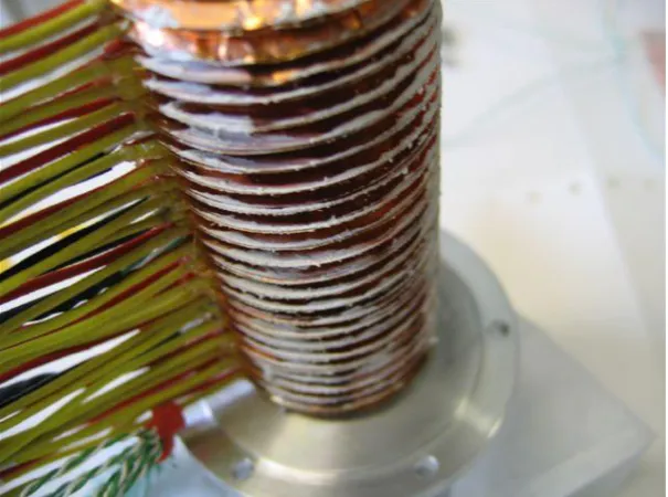
The stator, which is cylindrical in shape, contains a set of flat coils mounted around a thin-walled steel tube. After winding, each coil is impregnated with insulating varnish to form a stable compact
unit. During assembly six 25µm copper shims are sandwiched between each pair of coils to
facilitate heat conduction out of the coil stack. The addition of the copper shims gives a coil pitch of 3 mm. Connecting leads from the coils are led radially outwards. Three thermocouples are inserted between three pairs of coils to enable the temperature of the coil stack to be monitored. A coiled copper tube soldered onto a solid copper jacket is placed around the coils and is in contact with the copper shims. This carries the cooling water, the temperature of which is monitored at either end with two more thermocouples. The entire assembly is inserted into an aluminium outer cylinder, the stator body, with the insulated copper wires and the cooling pipes emerging through a slit in the side. The individual coils are wired up at terminal blocks placed external to the stator body.
3.2.1 Coils
The stator contains twenty-four identical coils that are stacked vertically and numbered one to twenty four starting from the top of the stator. The stator coils are responsible for interacting with the permanent magnets on the shaft both to levitate the target shaft when the target is being held out of the ISIS beam and to produce the accelerating force when the target needs to be inserted into the beam. (A motorised jacking platform is used to raise the target from the beam when not in use, as described in section4.5.)
Each coil is composed of thirty six turns of 0.56 mm polyester-imide enamelled copper wire, over-coated with a polyamide-imide resin. This yields a high temperature winding wire that is rated to 200◦C operation [10]. These coils are wound on an 18.1 mm diameter former, each coil having a depth of 2.85±0.1 mm. Coils outside this tolerance are rejected due to the limited space between
coils and the required pitch of 3 mm. The clearance of∼0.15 mm between the coils is used to
insert thin copper shims which act as heat sinks. After winding, the outer diameter of the coils is 30 mm. Each coil is double dipped into a varnish that seals the windings and provides additional electrical insulation [11]. Each coil is tested to 1 kV before being built into a stator. A photograph of a finished coil and some of the inter-coil copper shims is shown in figure3. The copper shims provide a thermal path between the coils and the cooling jacket. The inner diameter of the shims is 19 mm and the outer diameter 36 mm. The shims are split to reduce eddy-current losses.
3.2.2 Stator bore
A thin-walled non-magnetic stainless steel tube passing through the centre of the coils forms the stator bore. It provides isolation between the stator body and the ISIS vacuum and ensures the me-chanical alignment of the coil stack. The nominal wall thickness of 0.5 mm is reduced to 0.3 mm where it passes through the coils. The reduction in magnetic field strength within the bore caused by the stainless steel tube was estimated to be 1%. The stainless steel tube is insulated from the coil stack using three layers of self-adhesive kapton tape.
3.2.3 Cooling jacket
2013 JINST 8 P03006
Figure 3. A complete stator coil and some copper heat-sinking shims.
when the stator is levitating the shaft out of the beam, the power consumption is ∼30 W. Every
time the target is actuated an additional heat load of 400 J is deposited in the stator coils. The coils are small and therefore the heat capacity of the coil stack is correspondingly low. Without any heat-sink the coils would rise in temperature by∼5◦C with every actuation. Therefore, if this heat is not removed quickly, repeated actuation of the stator will rapidly result in the temperature of the coils rising above their maximum rated working temperature of 200◦C .
Unfortunately, the permanent magnets that are attached to the shaft will not operate up to this temperature without there being a serious risk of demagnetisation. The exact maximum safe operating temperature is hard to determine, as the Curie temperature is field dependent. There is also some evidence that the risk of demagnetisation at elevated temperatures is accentuated when
running permanent magnets in a radioactive environment [12]. Running the stator for extended
periods has demonstrated that coil temperatures of 80–90◦C do not lead to demagnetisation.
A cooling circuit is required to remove heat from the coil stack. This consists of an external, water-cooled, split cylindrical copper jacket. The jacket has a thin-bore, copper cooling tube sol-dered onto its outer surface through which a flow of water can be maintained. This is illustrated in figure4.
The inner diameter of the cooling jacket is slightly smaller than the outer diameter of the cop-per shims. When the jacket is slid over the coil stack this has the effect of bending the copcop-per shims over, thus ensuring a good thermal contact between them and the jacket. A photograph of the jacket placed over the coil stack is shown in figure5. The cooling pipe has a narrow bore and so the water flow rate is quite low. Typically, at∼4 bar, a flow rate of∼1 litre min−1 is achieved. This flow rate has proved to be sufficient to remove the heat from the coil stack during normal
operation. A nominal stator operating temperature of 80◦C has been maintained, well within the
2013 JINST 8 P03006
Figure 4. The copper cooling jacket is over-fitted with the water cooling pipes. The cooling pipes are soldered onto the jacket.
Figure 5. The cooling jacket, placed over the coil stack.
3.2.4 Stator assembly
[image:11.595.145.451.372.602.2]2013 JINST 8 P03006
Figure 6. All 24 coils assembled on a former. The copper shims can be clearly seen protruding from the coil stack where they will later make contact with the cooling jacket.
then added to the coil stack and the process is repeated for all twenty-four coils. As each coil has a nominal thickness of 2.85±0.1 mm the cumulative error is tracked and minimised during the coil stack construction by selection of coils of appropriate thickness. An assembled coil stack is shown in figure6.
The split in the copper shims aids in keeping the coils parallel during construction. This is achieved by placing the split in the shim where the wires to the coil exit. (There is sometimes a small bump at this point on the coil due to the wire exiting from the centre of the coil back over the top of the other windings). The gap created by the split in the shims also allows thermocouples to be inserted into the coil stack.
At this stage a cooling jacket is slid over the coil stack. The stator body is then completed by adding a split outer jacket and two end-caps. The split in the outer jacket allows the wires and the cooling pipes to protrude for external connection. The end caps provide light compression on the coil stack, keeping it in place. The former on which the coil stack was formed is now removed and the bore tube inserted through the bore of the stator. A final electrical insulation check is then per-formed, to ensure that all coils remain isolated from metal parts including the bore tube and cooling jacket. The installation of the stator body into the core of the target drive assembly is described in section4.
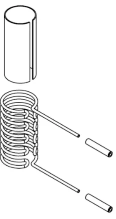
3.3 Permanent magnets
2013 JINST 8 P03006
Figure 7. Drawing showing the structure of the magnet assembly.
They are glued to a mild steel core to produce a cylinder that is 18 mm long with an outer diameter of 15 mm and an internal diameter of 4 mm. Thin ceramic washers separate the three rings. The central ring is 7.8 mm long, twice the length of the two outer rings. The whole assembly has a mass of about 25 g.
The individual sectors are manufactured by wire erosion from un-magnetised NdFeB mate-rial. The sectors are then magnetised radially and assembled in a jig before finally being glued in position using a strong two-component epoxy. Once the glue is cured, the magnet unit is lightly machined to the precise outer radius required. The middle ring is magnetised so that the outer surface is a North pole, while the outer rings have the opposite polarity.
A FLUKA [13] simulation has been performed to ascertain the radiation levels expected
around the target. Assuming 24 hour operation at 1 Hz for 180 days in a nominal year, the
ex-pected radiation dose to the magnets is estimated to be ∼1×10⁴Gy. To date, no evidence of
degradation due to radiation has been observed.
4 Mechanical design and construction
The MICE target unit contains mechanical components and sub-assemblies that are designed to:
• Combine accurately all mechanical, electronic, electrical-power and optical-readout
func-tions into a single unit;
• Provide a vacuum tight volume connected hermetically to the ISIS beam-line;
• Enable target operation by:
2013 JINST 8 P03006
Figure 8. MICE target assembly, (left) with bellows removed, (right) a cutaway view (Descriptions and information on the components in the assemblies shown here follows).
– Enabling the velocity and location of the shaft to be determined;
– Constraining the shaft along its path of travel thus preventing significant off-axis move-ment;
– Providing stiffness in the shaft that resists significant deformation and vibration during operation.
• Eliminate the possibility of a failure that prevents continued operation of ISIS beam, includ-ing:
– Breaking of the shaft such that part falls into the circulating beam;
– Failure of welds or seals causing a leak into the ISIS vacuum chamber; and
– Contamination of the ISIS vacuum chamber, particularly with metallic or other dust
that could contaminate the RF cavities.
2013 JINST 8 P03006
Figure 9. MICE target shaft assembly (shown horizontally oriented, operates vertically with tip down).
4.1 Target shaft
The shaft comprises of two sections of titanium (Ti) alloy grade 5 (6% Al, 4% V). The sections are a solid upper section and a lower tubular section with various functional features on each. The two halves are joined with a shrink-fitted plug-and-socket arrangement then electron-beam welded together. The shaft is coated with a hard diamond-like carbon (DLC) coating that acts as a bearing surface. The shaft is finally fitted with a permanent magnet, a slotted graticule for position read-out and the associated fixings and fasteners.
The shaft is 528 mm long and, when fully assembled with the magnet, slotted graticule and
fixings, has a weight of∼51 g. A radially segmented, permanent-magnet assembly is bonded to
the shaft and held with a mechanical clamp of minimal mass (1.5 g). The stator accelerates and then decelerates the shaft in both the down-stroke and the up-stroke with a maximum travel in each direction of around 48 mm. The shaft achieves this 96 mm of reciprocating movement in about 30 ms before dwelling and then dipping again; with the dwell the shaft dips at a frequency of just
under 1 Hz. The tip of the shaft has a cylindrical cross section of∼11.5 mm2 (5.95 mm outside
diameter and 4.55 mm inside diameter); as it is an integral part of the tubular lower shaft it is grade 5 titanium alloy. It is the tip of the hollow cylinder that momentarily grazes the halo of the ISIS beam to produce pions.
The production quality of the target shaft is the most critical aspect of all the manufacturing process. The shaft is manufactured within very tight dimensional and geometric form tolerances. The tight dimensional tolerances ensure the close fit of the shaft with the bearings; this tight fit accurately constrains the shaft’s vertical motion. The shaft requires a high degree of straightness and good roundness. Tight tolerances of form (cylindricity and run-out) are applied to the man-ufacture of the shaft; accurate form minimises deformation and vibration of the shaft during the rapid acceleration and deceleration.
4.1.1 Design
2013 JINST 8 P03006
Figure 10. Output plot of FE modal analysis of shortened shaft with ‘O’ shaped lower section.
resonant modes, reduces the number of resonant modes the shaft passes through as it is accelerated and decelerated. Excitation of vibrations in the shaft may arise from a number of sources, including:
• Large changes in velocity take place at∼15 ms intervals, i.e. twice over the 30 ms cycle. If the natural frequency of the shaft is close to 33 Hz or 67 Hz some distortion will be induced.
• The switching of power from one set of coils to the next may introduce an excitation force. The longitudinal driving force (up to 50 N) may be accompanied by off-axis torque or lateral forces as the sequential coil-switching takes place during dipping. The frequency and sever-ity of the excitation would be directly linked to the timing and magnitude of these forces. The timing of the switching is variable as the shaft is accelerated and decelerated in both directions, so the frequency of excitation is variable too. This may cause the shaft to pass through several excitation frequencies that correspond to the shaft’s resonant frequencies. The magnitude of the excitation depends on the force seen by the shaft when switching be-tween coils; this is related to the quality of the coils and their axial location relative to the permanent magnet. With a 0.5 mm offset in coaxiality between the permanent magnet and the coil’s magnetic centre the lateral forces have been calculated to be up to 2.5 N and the torque up to 32.5 mN m.
• The unit or surrounding support frames may be excited by the dipping shaft. There is poten-tial for this vibration to transfer back from the support frame to the shaft through the stator and the bearings. There is significant vibration felt on the test frame after each dip.
A tubular, ‘O’ section shaft was shown to have sufficient stiffness. A finite-element (FE) modal analysis showed the 1st and 2nd resonant modes at 50 Hz, but the 3rd and 4th at 68 Hz.
2013 JINST 8 P03006
Figure 11. Plug and socket detail, upper shaft on left, lower shaft on right.
The upper shaft stock material is stress-relief heat-treated before manufacture. It is then ground; this includes the flats which are very finely ground to ensure internal stresses are min-imised. A larger diameter is left at one end onto which the socket for the shrink-fit joint is ma-chined. Also added are the undercut for the magnet clamp and the fixing holes for the laser readout graticule. The very fine slot for the graticule is then cut by wire erosion. The wire erosion of this slot causes the two adjacent sections to open in a ‘Y’ shape. (This is only seen on the grade 5 tita-nium shafts and not on the previous versions made from commercially pure Ti grade 2; in fact the slot collapsed slightly when using Ti grade 2.) It appears the wire cutting causes a slight expansion in the surface material on the inside of the slot that forces these sections to fan out. This has been resolved by supporting the shaft with the slot closed and stress-relieving back to a correct form.
To alleviate the risk of undertaking so many operations on a long single-piece shaft it is pro-duced in two sections. The additional benefit of this is that they can be propro-duced concurrently with benefits to the schedule. The lower shaft has an accurately machined socket and the upper shaft has a mating plug. The plug and socket are manufactured with a nominal 0.01 mm interference press fit. If these were pressed together at ambient temperature the material would cold-weld. Cold-welding is unlikely to be uniform and so the joint would skew causing a significant form error between the upper and lower shaft sections; it may even seize before it is fully pressed together. To achieve a clearance as they are assembled (i.e. to prevent cold welding or galling) the socket is expanded by heating to 250◦C and the plug is shrunk by cooling to−190◦C in nitrogen. A precision jig is then used to ensure correct alignment as the pieces are pushed together. The interference-fit is made as the joint comes back to room temperature, contracting the socket and expanding the plug.
2013 JINST 8 P03006
Figure 12. Failed weld and displacement of shaft halves after tensile testing.
however under-run or over-run at the end of the weld always made the two halves skew too much. Tensile testing was used to determine the strength of the shrink-fit and point-welded joint. Tensile testing broke the spot-welds at 4 kN which coincided with an audible crack as the welds broke. Af-ter the welds broke the inAf-terference-fit of the plug and socket prevented the shaft breaking into two halves; instead the tensile load began to climb in finite steps against displacement to 6 kN before the test was stopped. This was due to a cold-welding effect; this is beneficial as it significantly reduces the chances of the shaft breaking into two should high impact load occur during a fault.
4.1.2 Material
Titanium is a good target material with respect to particle production, it is widely available, it can be easily worked and can be joined by welding. The shaft needed to be low mass to enable rapid and efficient acceleration by the stator. The shaft also needed to be stiff to minimise elastic deformation and vibration during its operation; titanium and its alloys have a good stiffness-to-mass ratio.
The initial redesign of the lower shaft led to the use of a tube with a mechanical stop welded on; tube in unalloyed grade 2 is widely available and was initially chosen for the shaft material. Impact testing was undertaken on this welded-stop design; this closely represented a shaft’s mechanical end stop impacting the lower bearing at a maximum speed of 9.3 m s−1during a fault condition, in-cluding a safety factor of 1.5. A mass was dropped from a set height onto the stop on the lower shaft. This stop failed at around 4 impacts. In addition a bulge started to form in the wall of the tube due to the impact, see figure13. Though the EB welding is a semi-automated process there is potential for variability in the strength of the weld, so the welded-on stop was not an entirely risk-free choice. In addition the welding of the stop caused some distortion to the tube that had to be corrected by mechanical manipulation. It was decided to pursue a more costly manufacturing route to produce a stop integrated into the lower section from a single bar, a much stronger design. This overcame the restriction of obtaining only grade 2 tube and allowed consideration of titanium alloys.
2013 JINST 8 P03006
Figure 13. A bulge can be seen in the shaft under the stop. This occurred during impact testing.
grade 5 is easier to grind, allowing better finishes and tighter tolerances to be achieved. This is particularly useful for the upper shaft where the diameters and flats are ground.
4.1.3 Manufacture
Grinding is used to produce the main geometry of the upper shaft. The depth of cut in the grinding process is reduced towards the final cut to minimise the amount of deformation induced into the surface of the component; this in turn minimises internal stresses in the final shaft. Internal stresses may relax via strain over time leading to warping of the shaft. Grinding also gives the shaft a fine surface finish so that polishing removes only a minimal amount of material in achieving the final surface roughness of 0.05 Ra.
Stress-relief annealing is undertaken on raw materials before processing as well as at cer-tain stages throughout the processing. This removes internal stresses induced by manufacturing
processes. Unrestrained heat treatment to around 670◦C with a dwell period of 40−50 minutes
followed by a slow cool relaxes the stresses through strain, which deforms the material slightly. This deformation is removed during subsequent processing to achieve the final component’s size with minimum internal stresses. The temperature and heat treatment cycle information was taken from [14].
dis-2013 JINST 8 P03006
Figure 14. Shaft in straightening jig.
similar material to the titanium alloy so there is less chance of the jig and the shaft bonding at the elevated temperatures during heat treatment. The latest shafts have all undergone this process and
have been straightened from >0.5 mm run-out post manufacture to around 0.1 mm run-out post
treatment.
Conventional machining, such as milling and turning, is used on many features including the profile of the lower shaft, the fixing holes for the graticule and the plug-and-socket features used to join the upper and lower shaft sections.
Wire-erosion is used to create a 90 mm by 0.22 mm slot in the upper shaft to support the graticule. The 4.55 mm inner diameter, 320 mm long bore through the lower shaft is also made by wire-erosion.
The sub-components of the shaft, and the fully-assembled shaft, are inspected at many stages during manufacture to determine if they meet the specification on the technical drawings. Further information on the inspection of the shaft is given below.
Diamond-like carbon (DLC) coating is applied to the bearing surfaces of the target shaft. These surfaces are polished prior to DLC coating to ensure the final finish is smooth. The tip of the shaft that dips into the beam is not coated. The tip is left uncoated to prevent any thermal heating, from contact with the ISIS beam, causing failure of the coating through high temperature (>400◦C ) or through thermal strain differentials.
4.1.4 Shaft measurement
bear-2013 JINST 8 P03006
Figure 15. DLC coated shaft, dark grey/black coating extending over and beyond the bearing regions of shaft.
ing regions as well as finely balancing material about the axis of the shaft. Manufacturing includes the use of jigs to hold the shape during processing, heat-treatment stages to relieve stresses and a final constrained heat-treatment to achieve the desired shape. Shafts are accepted with a run-out between bearing regions of less than 0.12 mm; through prototyping it was proved that shafts with such run-out operated acceptably in the target unit.
2013 JINST 8 P03006
4.2 Target bearings
4.2.1 Description
Plain bearings support and constrain bearing regions on the shaft. There are two bearings, one to restrain the upper section of shaft and one to restrain the lower section. They are required to constrain the lateral motion of the shaft as it dips, as well as incorporating an anti-rotation feature to prevent significant rotation about the longitudinal axis of the shaft. The upper bearing has the anti-rotation component; it is finely adjustable via screws to ensure accurate location with respect to the anti-rotation flats on the upper shaft. The bearings have plastic (Vespelr SCP5000) inserts and anti-rotation components (the dark items in figure 16). The plastic parts are assembled into stainless steel (Nitronicr 60) carriers. Nitronicrwas chosen as it minimises cold welding when the fine location taper on the outside of the bearing carriers are lightly pressed into the tapered bearing seat in the 1.4404 / 316L stainless steel body.
4.2.2 Material
For the bearings the material and coating combinations at the bearing interface with the shaft were very important for function and longevity. A number of material and coating combinations have been tried for use on the target. From the early trials of different coatings, a diamond-like carbon (DLC) coating on both the shaft and the bearing was found to be suitable. Despite these early successes, there subsequently appeared to be too much variability in the quality of this coating. This may have been due to the geometry of the parts being coated; the small bearing hole, even if produced in several segments, produced a “hollow cathode effect” in the RF coating chamber, thus variability in the thickness and adhesion of the DLC coating. This variability led to coatings on some shafts and bearings wearing away rapidly in later trials.
The alternative to DLC came from cryocooler technology as designed and built by STFC’s
Cryogenics and Magnetics Group. The cryocoolers have demonstrated in excess of 1010 cycles
in a dry helium atmosphere. The material combination used in these cryocoolers is titanium (both
commercially pure and 6% Al, 4% V) against VespelrSP-3 grade. The SP-3 grade of Vespelris a
polyimide that contains molybdenum-disulphide (MoS2). MoS2is a dry lubricant which lowers the
coefficient of friction. However MoS2was rejected on the grounds that long-lived isotopes might
be produced in the high radiation environment. DuPontTMTechnical were contacted to determine
if an unfilled alternative may be suitable. From the following requirements it was determined that
VespelrSCP5000 would meet the needs of the target when operating on the ISIS beam-line.
Bearing surfaces have a higher coefficient of friction in the ISIS vacuum of 10−7mbar [15], i.e. without the presence of moisture or lubricating films. A high coefficient of friction between bearing surfaces will increase the power required to drive the shaft, it will cause accelerated wear of the bearing surfaces and it will raise the temperature at the bearing interface through frictional heating. SCP-5000 was recommended for use as it has a relatively low coefficient of friction, even in a vacuum environment, of 0.26 or better [16].
2013 JINST 8 P03006
2013 JINST 8 P03006
Figure 17. Dust ‘can’ assembly, that captures the dust below the lower bearing.
Particles created during wear should be kept to a minimum. If they are created they must be managed and contained within the unit. This is particularly important for particles that have become activated, for health and safety reasons. In addition particles should not be released from the unit as they may damage the RF cavities adjacent to the MICE target in ISIS. Dust is produced when using
the Vespelr bearings, however with a finely polished shaft this has been minimised. The target
unit has been fitted with an extended housing with dust-traps to prevent the dust produced from the Vespelr escaping outside of the unit, see figure17. The bearing surfaces need to withstand a significant operational life and be able to be manufactured with fine surface finishes and tight tolerances to minimise the rate of wear; Vespelris a relatively hard plastic so suits this.
The material must not significantly out-gas in the ISIS vacuum. Out-gassing tests were
under-taken on vacuum-baked samples of VespelrSCP5000 (80◦C for 72 hours) which were shown to
be acceptable for use on the ISIS beam-line provided the total volume was kept below 3 cm3.
4.2.3 Rotational constraint
The position of the shaft is determined using an optical vane (section 5.1) which must be held
2013 JINST 8 P03006
Figure 18. Upper bearing with Vespelr bearing insert and anti-rotation component.
4.3 Stator
4.3.1 Description
The stator assembly surrounds the middle portion of the shaft assembly, including the permanent magnets which are driven by the coil stack. The bearings and stator assembly are fixed in the core structure (see below) to coaxially align the shaft assembly and permanent magnet with the coils.
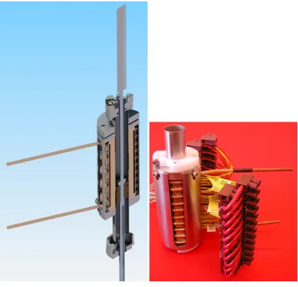
The stator, described in section3.2, is a self-contained sub-assembly; it is assembled around, but not fixed to, the central vacuum tube. As it is self-contained it can be tested independently. After assembly and test the stator unit is incorporated into the target unit by welding the ends of the vacuum tube into the two main core body components. The tube and welds provide an uninterrupted vacuum volume though the middle of the unit. Above and below this central vacuum tube, the components are fixed to the body with copper knife-edge (CF) seals. When the stator drives the shaft there is a reactive force of up to 50 N. As the stator is not fixed to the vacuum-tube this load is not transferred to the vacuum-tube welds. To prevent the coils within the stator moving, or the stator moving as a whole, the stator unit is clamped down inside the core body using three stacks of disc springs. These springs exert a clamping force of around 100 N onto the stator unit when the upper flange of the core body is fully tightened onto the core tube.
4.4 Core structure
2013 JINST 8 P03006
Figure 19. (Left) Stator assembled with shaft and disc spring plate on top, wiring not shown; (right) Tested stator unit ready for assembly (shown with temporary plastic clamps).
The core is required to align the other components accurately and stably, in particular to pro-vide the accurate coaxial alignment of the permanent magnets on the shaft and the stator coils. Careful consideration of the interfaces between the permanent magnet and the stator coils was re-quired. The order of the interfaces relating to this critical alignment of the permanent magnet and stator coils are represented by ‘→’, and are shown below:
permanent magnet→Shaft→Bearings→Core structure→Vacuum tube→Stator coils.
2013 JINST 8 P03006
Figure 20. (Left) Core body assembly with welded vacuum tube, (right) core tube body with upper flange assembled on top with fasteners and taper dowels.
Accurate alignment of the bearings is also very important. The bearing alignment, bearing-bore accuracy, straightness of the shaft and tolerances on the outer diameter of the shaft all build up to increase the minimum radial clearance tolerable between the bearings and the shaft. Keeping this radial clearance to a minimum ensures the shaft’s travel is well constrained. If the radial clearances have no added compensation for manufacturing variations, the fit could be too tight which may lead to flexing of the shaft and possible fatigue failure or high power loading on the stator. To achieve accurate bearing alignment the core structure and the way it supports and locates the stator assembly has been simplified to the minimum number of components and interfaces. There are only two components and three interfaces between the 2 bearings:
bearing→Core lower→Core upper→Bearing.
2013 JINST 8 P03006
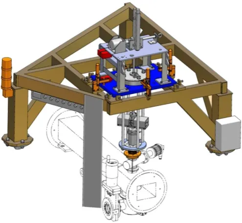
Figure 21. Target assembly suspended by rods from motorised stage above ISIS beam line, connected to beam-line with bellows.
The bobbin that supports the stator has a central bore where the permanent magnet runs up and down. The bobbin is welded into the core assembly so that it forms a hermetic seal from the flange on the upper flange to the flange on the core tube body. These flanges incorporate CF-type seal features which use knife edges to compress copper seals. A hermetically sealed internal vacuum volume is created when the optical housing and bellows are fitted to the core assembly and the bellows are then fitted to the vessel in the ISIS ring or the test vessel.
The core tube body has a small flange which is fitted with a larger flange extension. This ex-tension is the main reference component for positioning the assembly on ISIS. Rods are suspended from a frame, either above the beam-line or on a test vessel in a separate building (for offline run-ning and trials), as described in the next section. These rods fix to the larger flange extension and support the target unit for connection to the beam-line or vessel. The two-part flange is a practical solution for manufacturing as it minimises the material cut away from stock billets to form the components.
4.5 Mechanical integration
2013 JINST 8 P03006
Figure 22. Motorised platform.
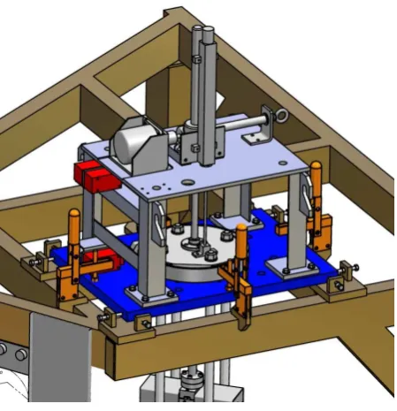
synchrotron and the target drive. A duplicate section of beam-pipe, complete with target support frame, is situated in an assembly hall where all target mechanisms were commissioned.
4.5.1 Motorised platform
A heavy steel plate rests on the main support frame. This carries a motorised screw-jack driven by a stepper motor (see figure22). The jack can raise and lower a steel ring, which carries the main target mechanism via four sturdy rods passing through holes in the plate. The jack has a travel of 207 mm and, when in its lowest position, the ring fits into a locating socket. The motor is controlled remotely, and limit-switches indicate when the mechanism is at its highest and lowest positions. The switches are interlocked to the control system to prevent the equipment from being driven out-side safe limits. An independent position switch is linked to the Personnel Protection System, and prevents the target mechanism being lowered while access is allowed to the MICE Hall and ISIS is operating.
The plate is supported on levelling screws, and its lateral position is adjusted with locking screws to ensure the target is centred over the port in the beam-pipe. Once positioned, the plate is clamped in place.
During normal target operation, the support frame is moved to its lowest position. The tip of the shaft is then outside the beam envelope only while it is magnetically levitated. When the target is not in use, the frame is raised to its highest position and the target is well clear of the beam even if powered down.
4.5.2 Bellows and ISIS vessel interface
2013 JINST 8 P03006
an internal diameter of 46 mm, a compressed length of 56 mm between flanges and an extended length of 260 mm. The UHV seal between the bellows and target flange is maintained with a standard Conflat seal and copper gaskets.
As a fault in the target mechanism could compromise the ISIS vacuum, it is important that the target vacuum space can be isolated from the accelerator. This is achieved with a gate valve, mounted between the flange on the upper face of the vacuum vessel and that at the lower end of the bellows. Seals are formed using aluminium gaskets compressed by V-band clamps. The valve is operated by a low-pressure nitrogen line, controlled remotely, and has an aperture of 40 mm to allow the passage of the shaft. The control system ensures that the frame cannot be lowered while the valve is closed and that the valve cannot be closed unless the frame is at its upper limit-switch. The ISIS vessel is adapted for the presence of the MICE target in several ways. As well as the port on the upper surface to accept the target mechanism via the gate valve and bellows, it has a thin-walled steel window to allow the passage of pions, produced by interactions in the target, into the MICE beam-line. In addition, it has a glass inspection window directly below the target. This allows visual observation of the shaft tip.
4.6 Magnetic inspection
To characterise the magnetic performance of the target mechanism, magnetic measurements are carried out on the stator and on the permanent magnet assembly. The equipment used is a three-axis Hall probe mounted on the end of a travelling arm. The position of the probe can be set to a resolution of 1µm in three axes.
4.6.1 Stator
For the stator, measurements are required to define the position of the magnetic centre of the coils relative to the mechanical centre. If the coils are offset, the small radial field they generate may have the effect of moving the shaft laterally as it passes through the stator. Accurate alignment of the magnetic centre is therefore important to minimise wear on the bearings during operation.
The coils are powered using a constant current of 7 A; this is lower than the peak current when the shaft is dipped into the beam due to heating concerns — a constant current of 60 A would overheat the coils. The current of 7 A heats the stator to around 50◦C when water cooling is used.
The stator is set up and aligned to the measurement bench. A cross-hair on the end of the Hall probe is viewed through a telescope as the probe is moved up and down the bench; this allows the telescope axis to be set parallel to the bench axis. Cylindrical inserts with a precisely machined central hole are placed in either end of the stator bore in turn, to allow the stator axis to be aligned parallel to the bench axis. The estimated accuracy of this procedure is around 100µm at each end,
which gives an overall alignment accuracy of 0.8 mrad over the 180 mm length of the stator. An initial scan of the stator along the longitudinal (z) axis shows a series of peaks correspond-ing to the individual coils. To find the centre of each coil, a two-dimensional scan at each peak position is carried out (figure24). The magnetic centre is the point at which the longitudinal field is a minimum. The longitudinal field is fitted to the function:
2013 JINST 8 P03006
Figure 23. (Left) Bellows shown assembled under core tube body; (right) Compressed and uncompressed bellows states.
The centre point can then be found from the fit to the data, using the formulae:
x0=
2bc−de
4ac−e2 ; y0=
be−2ad e2−4ac
4.6.2 Permanent magnets
2013 JINST 8 P03006
Figure 24. Contour plot of longitudinal field (Bz) versusxandy. The left plot shows the measured field, and
[image:32.595.87.503.82.292.2]the right plot shows a quadratic fit to the data.
Figure 25. Radial field versus angle for the permanent magnet assembly.
in the peak (and trough) values of the radial field. An assembly with smaller differences between the peaks would be preferable, as it may reduce lateral movement and vibration of the target shaft during operation.
2013 JINST 8 P03006
Figure 26. The optical vane. One side has 157 apertures to provide a quadrature signal. The other has a single slot to give a fixed reference point.
5 Optical position-measurement system
In order to switch the current through the coil stack at the correct time to drive the shaft, it is necessary to sense the position of the shaft while it is moving. To avoid disrupting the motion of the low-mass shaft by mechanical contact, and to remove the necessity for electrical feed-throughs traversing the vacuum wall, an optical method is adopted. Furthermore, since active electrical com-ponents would not survive in the high radiation environment near the target, optical fibres are used to convey the signals, with all sensitive electronics being placed outside the accelerator vault (in the experiment control room some 100 metres away).
A graticule, or vane, attached to the shaft and interrupting a light beam will generate a series of pulses, which could be used to determine the speed but not the direction of movement of the shaft. If it is arranged such that two beams are interrupted by the vane, with the pulse trains being 90◦out of phase, then both speed and direction can be determined. (This is known as a quadrature system.) With a third beam producing a pulse at only one well-defined point, a zero of position can be defined. In this way, by counting pulses away from the zero, an absolute position measurement can be made.
In addition to providing feedback to the controller, position measurement allows the trajectory of the target to be monitored and recorded by the data acquisition system. This enables the long-term monitoring of the stability of the mechanism and the diagnosis of fault conditions.
5.1 Optical vane
A photograph of the vane is shown in figure26. The vane is a double-sided graticule manufactured from 0.2 mm thick steel, having 157 slots 0.3 mm wide and 3 mm long on one side of a 6 mm wide spine. The whole vane is 93.9 mm long. The spacing between slots is also 0.3 mm. There is a single similar aperture two-thirds of the way down the vane on the other side. To protect the fine features of the vane, it has a continuous edge. The vane was produced by photographic etching, and is attached to the shaft by four M1.6 screws. In order to ensure that the readout system provides reliable position information, the manufacturing tolerances of the apertures were kept to less than 5% of the 150µm resolution, and the tracking error along the length of the vane was also less than
2013 JINST 8 P03006
5.2 Laser source
Three fibre-coupled solid-state lasers provide the light beams which intercept the vane. Commer-cial red (635 nm) lasers, with a variable 0 to 2.5 mW output power are used. Visible light has advantages both for alignment and safety. The milli-Watt power level is required due to significant losses in the optical system owing to the number of optical interfaces. Maximising the light on the optical sensors (section5.5) increases the signal to noise ratio and simplifies the design of the electronic amplifiers.
In practice, the lasers are not operated at maximum power, but at about 1 mW. This leaves sufficient overhead (both in light source and amplification gain) to adjust for any degradation in the optical fibres, e.g. increased attenuation as a result of radiation damage.
5.3 Optical fibres
Two types of optical fibre are used. On the transmitting side, single mode fibres are required to achieve the necessary small spot size at the focal point and hence at the plane of the vane. On the receiving side, 200µm multimode fibres are used.
The single mode fibres used are SM600 with FC-to-FC connectors [17]. These fibres have a
core of pure silica, which is a radiation-hard material and so ideal for the operating environment of the target. If single-mode fibres were used on the receiving side, the collimators would have to be aligned to an extremely high precision and it would be hard to achieve an adequate light transmission. Multimode fibres have a higher acceptance, so make the alignment less critical. The
fibres used are BFH37/200 purchased from Thorlabs, with SMA to SMA connectors [18].
5.4 Collimators, lenses and mechanical mount
Collimators and lenses are used to focus the light from the fibres to a spot in the plane of the optical vane (where it needs to be significantly smaller than the pitch of the vane) and to receive the transmitted light coupling it into the return fibre. The collimator is a commercial unit which produces parallel light from the diverging beam emitted by the fibre. Collimators with a focal length of 15.3 mm are used, as the longer focal length minimises the final spot size. The focusing lens, with focal length 45 mm, is attached to the front of the collimators by inserting it into a holder which is screwed onto the front of the collimator as shown in figure27. On the transmitting side, aspheric double achromatic lenses are used to obtain the minimum spot size. On the collecting side, where focusing is less critical, double convex lenses are used to re-collimate the beam. The lenses are MgF2coated to minimise reflections and maximise the light transmitted into the fibres.
2013 JINST 8 P03006
Figure 27. Cross section through a collimator and lens cap.
Figure 28. An exploded view of the optical mount. The optical vane sits inside the main body, where the collimators and lenses are able to focus the light.
2013 JINST 8 P03006
5.5 Optical sensors
The multimode fibres are returned to an SMA photodiode (H3R880IR) [19]. This is a broad
spec-trum photodiode (400 to 1100 nm). As the maximum velocity of the target is less than 10 m s−1, the maximum data rate per channel is only 33 kHz, well within the response capability of these devices. The outputs from the photodiodes are amplified and conditioned before being converted into digital signals.
6 Stator operation and power electronics
6.1 Introduction
The target drive is a three-phase, brush-less, permanent-magnet DC linear motor. Before consider-ing how the force on the magnetic assembly changes with respect to its position within a powered coil stack, it is necessary to understand how the coils in the stator are wired and how they are switched.
The 24 coils in the stator are split into three phasesA,BandC, with eight coils in each phase. Starting from the top of the coil stack (see figure29), the coils are lettered in a cyclic sequence that follows the pattern,A B0 C A0 B C0. A block of six coils labelled in this way is called a “bank”. This sequence is repeated four times so there are four banks of coils in the target stator, as shown in figure29. All theAandA0 coils are wired together in series, as are theBandB0 coils and the
CandC0 coils. The unprimed and primed coils are wired such that when a current passes through
either anA,BorCcoil in a clockwise direction, the same current passes through anA0,B0orC0coil in an anticlockwise direction. The induced magnetic field direction for a primed coil is therefore opposite to that of an unprimed coil. There are two connections for each phase, one at the top of the stack and one at the bottom. The three separate connections at the bottom of the stack are wired together to form the “star-point”, while the three at the top are connected to the stator power supply, as shown if figure30. If current is fed into one of the phases then it must return through one (or both) of the other phases. Therefore when current flows, at a minimum two phases must have current passing through them.
6.2 Coil current switching sequence
For the target mechanism, only two of three phases are ever powered at the same time,1 i.e. one
phase is switched to provide the current source and another phase provides the return path. This op-eration is slightly different from the usual method of driving each phase with a phasor, but reduces complexity at the cost of only a small reduction in efficiency. With three phases, current can there-fore be switched through the stator in six different ways. Using the external connection labelsA,
B0andCas shown in figure30, these six states are:A→B0,A→C,B0→A,B0→C,C→AandC→B0. By stepping through these six states in a predetermined order, the coils can be switched to create a “ripple” motion in the magnetic fields generated within the stator, as illustrated in figure31. The di-rection of motion is determined by the didi-rection in which these states are stepped through; when re-versing this order the ripple motion moves in the opposite direction. By tracking the position of the
2013 JINST 8 P03006
Figure 29. The relationship of phase of the coils to their physical position within the stator. Coils marked with a prime are wired so that current flows through them in the opposite direction to those that are unprimed.
Figure 30. The wiring of the coils in the stator, illustrating the star point and the three external connections
from the stator. Each coil in the diagram represents 4 coils i.e. theAcoil represents theAcoil from banks
1 to 4.
[image:37.595.241.354.408.608.2]2013 JINST 8 P03006
Table 1. The six states that create an apparent upward motion in the fields generated within the stator. The states are circular. Moving through the states in the opposite direction reverses the apparent motion.
State Current Flow
1 A→B0
2 A→C
3 B0→C
4 B0→A
5 C→A
6 C→B0
Figure 31. Switching the coils through the circular sequence given by States 1 to 6 gives an apparent motion in the coil switching upwards through the stator as illustrated. Reversing the sequence gives an apparent downwards motion. The pattern repeats itself every six coils. The permanent magnets on the shaft can be made to interact with the fields produced by passing sequentially through these states to produce motion of the shaft.
6.3 Magnetic assembly and modelling
As described in section3.3, the magnet assembly is composed of 3 radially magnetised rings, with a total length of 18 mm, matching the depth of 6 coils. This distance corresponds to the symmetry of the axial field, and alignment of the magnets with these fields gives the ability, with suitable feedback, to either hold the magnetic assembly in a predetermined position or to maximise the accelerating force on the permanent magnets.
2013 JINST 8 P03006
Figure 32. Simulation of the force on the magnetic assembly as a function of its position within the stator when the stator is in one of its six states with a coil current of 58 A. A good sinusoidal fit can be made to these points as illustrated.
arbitrary due to the symmetry of the device.) The model is axisymmetric inR, zand the origin is placed at the centre of the stator, corresponding to a plane that sits on top of the 13thcoil. For this
model a current of 58 A was assumed to flow through the coils, approximately equal to the peak current during operation. The simulation ran over several iterations and, with each iteration, the magnetic assembly was moved in either 0.5 mm or 1 mm increments axially along the centre line of the stator over a total distance of 20 mm. The maximum force on the magnetic assembly was calculated for each position. The results are shown in figure32, which shows a clear sinusoidal pattern for the resultant force on the magnetic assembly and a sine wave can be fitted cleanly to the simulation results. Although not illustrated here, the sinusoidal pattern of the force curve repeats every 18 mm, the length of one bank of coils. Further simulations confirmed that as the magnets move towards the end of the stator bore there is no deviation from this sinusoidal pattern, as the magnet assembly is always completely contained within the coil stack so end effects are minimal.
6.4 Zero-force points
2013 JINST 8 P03006
Figure 33. If the shaft was sitting at the zero-force point that corresponds to “State 4” and the stator was switched to “State 5” then the magnets would see a restoring force (black arrow) that would move the shaft to the new zero force position (red arrow) 3 mm further up the stator. By repeatedly incrementing or decrementing the states the shaft can be moved up and down the stator body. This simulation shows the force for a 3 A coil current typical of that used to levitate the shaft.
would result in the shaft undergoing damped harmonic motion (where the damping would primar-ily come from the frictional forces between the shaft and the bearings). The drive is designed to be a high-acceleration device, accelerating the shaft in excess of 80g, so providing a force greater than 80mg, where mis the mass of the shaft complete with magnets etc. Stable levitation occurs when the electromagnetic force on the shaft balancesmg. To a good approximation the force scales linearly with the coil current so stable levitation of the shaft in close proximity to these zero-force points can be achieved with a current that is much smaller than that required to achieve the high accelerations needed to insert the shaft tip into the ISIS beam.
The zero-force points in figure32are shown for the stator in “State 4”. If the state sequence is progressed then the positions of these zero-force points move in step with the state sequence. Moving forward through the sequence moves the zero force points up through the stator in 3 mm increments, likewise moving backwards through the sequence moves the zero force point down the stator in 3 mm decrements. If the zero-force point is used to levitate the shaft then the target will track the movement of these zero-force points as the state sequence is progressed. When the state changes the shaft will move to the new point, as a restoring force will push the shaft to the new equilibrium position. This is illustrated in figure33. The shaft will undergo damped harmonic motion as it settles at this new point.
2013 JINST 8 P03006
“parked” position, and then moved to its holding position by progressing cyclically through these states. This final state, the “hold mode”, then holds the shaft indefinitely until actuation is required. Reversing the process allows the shaft to be lowered back down to its “park-mode”.
Using the stator in this way to control the shaft limits the “hold position” of the shaft to one of a set of predefined points that are 3 mm apart. This means that the hold position is not entirely arbitrary, but the 3 mm step size gives enough freedom to ensure that the shaft is held out of the ISIS beam. This system of moving the target shaft by allowing the magnets to track the position of the zero-force points is entirely passive and does not require any positional feedback to operate.
6.5 Actuation
From figure32 it can be seen that the zero-force point is half way between two maximum-force
points; we define a maximum-force point as a position within the coil stack where the magnets on the shaft would experience a maximal repulsive force. For each set of two maximum-force points, one of them will push the magnets in one direction whilst the other will push the magnets in
the opposite direction. Figure32shows that these maximum-force points are positioned±4.5 mm
away from the zero-force points; this is of course true for any zero-force point in any one of the six possible states. It can be seen that the forces change very little±1.5 mm either side of the peak. Integration of the fitted sine wave±1.5 mm either side of the peak shows that the average force is 95.5% of the peak force. If the shaft was levitated at a zero-force point and the coil state was either to increment or to decrement by two states this would put the magnets 1.5 mm on the far side of one of the maximum-force points as the zero-force point would have been moved by 6 mm. The shaft would then accelerate back towards the shifted zero-force point. In either case the resultant force would cause the shaft to pass through the location of the maximum-force point during the first 3 mm of acceleration, as illustrated in figure34.
If, after switching the coil two states, no further switching was done the shaft would continue to accelerate towards the new zero force point 6 mm further up or down the coil stack and would execute damped harmonic motion about this point until it came to rest. However because the position of the shaft can be tracked using the optical quadrature system, another state change can be made when the target has travelled 3 mm, placing the magnets 1.5 mm on the far side of the next maximum-force point. This has the effect of maintaining a maximal accelerating force on the shaft. This process can be continued down the entire length of the coil stack as illustrated in figure35. If the shaft is accelerated via this mechanism, deceleration can be achieved by switching the coil state by three positions. This has the effect of placing a force of equal magnitude but opposite direction on the permanent magnets. Once again, by referring to figure32and comparing this to figure31, it can be seen that a switch of three states changes the direction of the accelerating force because it simply reverses the current flow through the coils. If a previously accelerated shaft is decelerated by this process then there will be a point where the shaft will change its direction of motion.
2013 JINST 8 P03006
Figure 34. If the shaft was sitting at the zero-force point that corresponds to “State 4” and the stator was switched to “State 6” (top) or “State 2” (bottom) then the magnets would see a restoring force (black arrow) that would move the shaft towards the location of the shifted zero-force position. During the first 3 mm of
movement the shaft would see an average force that is≈96% of the peak force.
zero-force point and so, providing the shaft does not have a high velocity, capture of the shaft at the zero-force point is inevitable.
2013 JINST 8 P03006
Figure 35. The shaft moves from levitation (3 A coil current) to acceleration (58 A coil current). By tracking the position of the magnets the states can be switched to ensure the shaft continually accelerates using the maximum available force. This results in a large accelerating force on the shaft.
to within 150µm. As will be described in the next section, the high resolution of the optical system
allows better control of the stroke of the shaft. The use by the control electronics of the mechanisms described above is given in section7, while figure36shows the principle employed.
6.6 Coil switching and current control
It has been shown that by wiring the stator in three phases and applying the appropriate currents to those phases it is possible to control the movement of the shaft. To do this effectively there are two principal design requirements. The first of these is the ability to switch current bi-directionally through any two of the three phases, and the second is the ability to control the amount of current that passes through the coils.
Bi-directional switching of the three phases of the coil stack can be achieved using six transis-tors arranged in three pairs, where each pair of transistransis-tors is connected together in series between the power rails of the power supply. The mid-point of each pair of transistors then connects to one of the three phase wires of the coil stack. Figure37illustrates how these transistors are connected. This type of circuit is known as a “Hex Bridge” or “Three Phase Inverter”. The three transistors across the top of the circuit are called the “high-side transistors” as they are connected to the pos-itive power rail, while the other three are the “low-side transistors”. It is possible to see how this circuit can be used to switch the current bidirectionally through the phases by comparing table2
with figure37. The inputs are labelled Q1–Q6 in the figure.