Remotely Operated
Telepresent Robotics
A Dissertation submitted by
Jarrad Gleeson 13/10/2016
In fulfilment of the requirements of
ENG4112
Research Project
Towards the degree of
1 | P a g e
Abstract
Remotely operated robots with the ability of performing specific tasks are often used in hazardous environments in place of humans to prevent injury or death. Modern remotely operated robots suffer from limitations with accuracy which is primarily due the lack of depth perception and unintuitive hardware controls. The undertaken research project suggests an alternative method of vision and control to increase a user‟s operational performance of remotely controlled robotics.
The Oculus Rift Development Kit 2.0 is a low cost device originally developed for the electronic entertainment industry which allows users to experience virtual reality by the use of a head mounted display. This technology is able to be adapted to different uses and is primarily utilised to achieve real world stereoscopic 3D vision for the user.
Additionally a wearable controller was trialled with the goal of allowing a robotic arm to mimic the position of the user‟s arm via a master/slave setup. By incorporating the stated vision and control methods, any possible improvements in the accuracy and speed for users was investigated through experimentation and a conducted study.
Results indicated that using the Oculus Rift for stereoscopic vision improved upon the user‟s ability to judge distances remotely but was detrimental to the user‟s ability to operate the robot.
2 | P a g e University of Southern Queensland
Faculty of Engineering and Surveying
ENG4111/2
Research Project
Limitations of Use
The Council of the University of Southern Queensland, its Faculty of Engineering and Surveying, and the staff of the University of Southern Queensland, do not accept any responsibility for the truth, accuracy or completeness of material contained within or associated with this dissertation.
Persons using all or any part of this material do so at their own risk, and not at the risk of the Council of the University of Southern Queensland, its Faculty of Engineering and Surveying or the staff of the University of Southern Queensland.
3 | P a g e
Certification
I certify that the ideas, designs, and experimental work, results, analyses and conclusions set out in this dissertation are entirely my own effort, except where otherwise indicated and acknowledged.
I further certify that the work is original and has not been previously submitted for assessment in any other course or institution, except where specifically stated.
4 | P a g e
Acknowledgments
Firstly, to my friends and family for their continued support during my time at university and making every effort to help me start my career.
To my supervisor, Dr. Tobias Low, for the advice, feedback and the kindness of lending hardware to aid in the completion of this project.
And finally, to the awesome students who I have spent so much time with over the past 4 years at USQ. Your company has made my experience so much more enjoyable.
Jarrad Gleeson
5 | P a g e
Contents
Abstract ... 1
1. Introduction ... 9
1.1 Objectives ... 10
1.2 Expected Outcomes ... 11
2. Literature Review ... 12
2.1 General Types and Uses of Tele-operated Robotics and Remotely Operate Vehicles ... 12
2.2 Control Methods ... 16
2.2.1 Traditional Robotic Controls ... 16
2.2.2 Experimental Controls ... 16
2.3.1 Oculus Rift Iterations ... 18
2.3.2 The Head Mounted Display ... 19
2.3.3 The DK2 Lenses... 20
2.3.4 The Positional Camera ... 21
2.3.5 The Rift‟s Field of View ... 22
2.3.6 Rendering to the Rift ... 23
2.3.7 Cyber-sickness ... 24
2.5 Testing/Experimentation ... 27
2.6 The Human Depth Perception ... 29
2.7 Review of Information ... 31
3. Methodology... 32
3.1 Project Methodology ... 32
3.2 Testing Methodology ... 34
3.3 Risk Assessment ... 35
3.3.1 Identification of Hazards ... 35
6 | P a g e
3.3.4 Project Consequential Effects ... 36
4. Telepresent Robot Hardware, Operation & Integration... 37
4.1 Original Oculus Vision Hardware Components ... 37
4.1.1 CMOS Camera Module ... 39
4.1.2 5.8GHz Skyzone Wireless AV Video Transmitter & Receiver ... 39
4.1.3 Discussion of Original Design ... 40
4.2 OVRVision Pro Camera ... 42
4.2.1 Specification and Features of the OVRVision Pro ... 42
4.3 Single Camera/Monitor Interfacing ... 44
4.4 Six Axis Robot & Controls ... 45
4.4.1 The Six-Axis Robotic Arm ... 46
4.3.2 Robotic Gripper ... 47
4.4 Control Panel ... 49
4.4.1 Control Panel Arduino Code ... 51
4.5 Arm Controller ... 52
4.5.1 Interfacing Diagram ... 53
4.4.4 Preliminary Testing ... 54
5. Depth Perception Testing ... 55
5.1 Stereoscopic Depth Perception Test ... 55
5.1.1 The Created Test ... 56
5.1.3 Recording the Results ... 58
5.1.4 Informed Consent Form ... 58
5.1.5 Stereoscopic Depth Perception Test Preparation ... 59
5.1.6 Stereoscopic Depth Perception Test Overview ... 60
5.1.6 Aspects for Investigation ... 61
5.1.7 Hypothesised Results ... 62
5.2 Statistical Analysis of Stereoscopic Depth Perception ... 63
7 | P a g e
5.2.2 Evaluating the Accuracy of the Camera & Monitor ... 65
5.2.3 Evaluating the Accuracy using Stereoscopic Vision ... 67
5.3 Vision Method Accuracy Comparison ... 69
5.4 Analysing Questions from the Stereoscopic Depth Perception Test... 71
5.4.1 Most Accurate ... 72
5.4.2 Participant‟s Preference on Vision Methods ... 72
5.4.3 Impact of Cyber Sickness ... 72
5.4.4 Oculus Rift DK2 Immersion ... 73
5.5 Conclusion ... 74
5. Stereoscopic Vision & Robotics Testing ... 75
6.1 Stereoscopic Telepresent Robot Test ... 75
6.2 Robotic Test Preparation ... 76
6.3 Robotic Testing Overview ... 77
6.4 Test Walkthrough ... 78
6.5 Aspects for Investigation ... 82
6.6 Hypothesised Results ... 83
6.7 Statistical Analysis of Stereoscopic Telepresent Robot Test ... 84
6.8 Survey of Stereoscopic Vision Robotic Test ... 86
6.8.1 Most Accurate ... 87
6.8.2 Participant‟s Preference on Vision Methods ... 87
6.8.3 Impact of Cyber Sickness ... 87
6.8.4 Oculus Rift DK2 Immersion ... 88
6.8.5 Gripper Operation ... 88
6.9 Conclusion ... 89
7. Results & Discussion ... 91
7.1 Project Outcome ... 91
7.2 Recommendations for Future Work ... 92
8 | P a g e
7.2.2 Haptic Feedback ... 92
7.2.3 Reducing the Occurrence Cyber Sickness ... 93
7.3 Final Conclusion ... 94
References ... 95
Appendix A ... 98
Appendix B ... 101
Appendix C ... 102
Appendix D ... 104
9 | P a g e
Chapter 1
Introduction
Engineers in the field of automation and robotics have developed many devices with the aim of performing tasks on behalf of people in environments that are considered hazardous to humans. This range of robotics use extends from applications such as deep sea and space welding to bomb and land mine disposal operations. Many of these robots and machines rely on control methods such as joysticks, buttons and traditional video telemetry to be operated and interact with the real world.
The final year research project investigates stereoscopic vision and alternative control methods to determine if user interaction and operation of remotely controlled robotics can be improved. The project scope includes the design, construction and operation of such a device termed as a “remotely operated telepresent robot”. The robot itself includes a platform with a robotic arm and two cameras mounted on a gimbal to achieve a sense of depth perception for the user when operated remotely.
10 | P a g e
1.1
Objectives
The objectives in order that the project aimed to achieve through research and implementation were:
1. An increase in accuracy for remotely controlled robotic limbs through improved vision for the user by implementing depth perception and directed camera movement. The device used to investigate this was the Oculus Rift Development Kit 2.0.
2. The development of a wearable control apparatus worn on the user‟s arm to control a
robotic arm which can mimic the position of the users arm. This focuses on reducing the learning curve for a user by providing a more natural control method.
3. Compare the proposed research project vision and control methods against traditional methods in terms of speed, accuracy and usability for multiple users to determine if user operation can be improved through the implementation of newly developed technologies.
11 | P a g e
1.2 Expected Outcomes
The project has been designed to utilise newly developed technologies (Oculus Rift DK2.0) in the field of robotics as well as the design and construction of a wearable form of controller to mimic that of human movement. As limited research has been conducted into this area, this study will provide useful information in regards to speed, accuracy and usability for multiple users to determine if there can be an improvement in regards to user operation.
The expected outcomes at the conclusion of the project include:
The development of a new remotely controlled telepresent robot
Detailed information on whether the Oculus Rift can provide an advantage over normal camera-monitor combination for users
Detailed information on whether a wearable control apparatus can provide an advantage over joystick and button for users
How easily this technology is can be adapted into robotics
12 | P a g e
Chapter 2
Literature Review
This section contains the relevant information in regards to remotely controlled tele-present robotics. More specifically the topics of literature reviewed include:
The general types, features and uses of remotely operated robotics Current robotic control and vision methods
The Oculus Rift Development Kit 2.0 OVRVision Pro Stereo Camera Testing/ Experimentation The Human Depth Perception
2.1 General Types and Uses of Tele-operated Robotics and
Remotely Operate Vehicles
13 | P a g e
There is a great need for devices which can perform the task of safe EOD either autonomously or by user operation. The removal of landmines has become a global emergency with over 100 million landmines still actively placed in the ground worldwide. As a result, the loss of over 20 thousand lives occurs every year with the vast majority being civilians. (Portugal, Cabrita, Gouveia, Santos, & Prado, 2015), (Wojtara et al., 2005),(Albert, Mason, Kiing, Ee, & Chan, 2014)
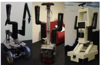
The research and development of robotic solutions has had the ultimate goal of safeguarding lives by keeping humans away from the threat while increasing the clearance speed in a cost-effective manner (Portugal, Cabrita, Gouveia, Santos, & Prado, 2015). These robotic solutions include features of intuitive human-machine interfaces with real-time interaction and the possibility to remotely control the robot within safe distances while maintaining portability (Portugal, Cabrita, Gouveia, Santos, & Prado, 2015). Figures 2 and 3 depict commonly used EOD robots which are operational in the field today.
Figure 1:The FSR Husky demining robot Figure 2: Northrop Grunman HD-1 Source: (Portugal, Cabrita, Gouveia, Santos, & Prado, 2015)
14 | P a g e
Figure 3: Little Hercules
(Source: Ocean Explorer, 2015)
Not all tele-operated robots are designed with the specific intent of operating in environments which would be considered dangerous to humans. Healthcare and Medical applications are another key driving force behind research into the advancements in user operated robotics. Currently automated robotics can only deal with very specific tasks in very specific situations. Researchers such as van Osch, Bera, van Hee, Koks, & Zeegers, 2014 believe that for robots to be made applicable in domestic environments in the near future, human operators must stay in the loop. This belief is due to technology still not able to prevent a robot from being cornered or stuck. A manual form of control is required to help the robot continue on its way. Robots such as those created by van Osch, Bera, van Hee, Koks, & Zeegers, 2014 are utilised to assist the elderly and disabled. This class of robots has been termed as Tele-operated Service Robots (TSRs) and are described as robots which are controlled by a human being from a distance which perform tasks that are typically in an uncontrolled environment.
The robot ROSE has been developed (van Osch, Bera, van Hee, Koks, & Zeegers, 2014) to combat the increase in the population of the elderly and the reduction in the working population. Today there are not enough people who are available to take care of the elderly. The Elderly and the physically disabled mostly want to stay at home and maintain their independence for as long as possible. (van Osch, Bera, van Hee, Koks, & Zeegers, 2014)
15 | P a g e
[image:16.595.329.500.133.243.2]of a joystick to control both the arm and the main platform (van Osch, Bera, van Hee, Koks, & Zeegers, 2014). Figures 5 and 6 depict a TSR and their function.
[image:16.595.71.283.136.274.2]16 | P a g e
2.2 Control Methods
2.2.1 Traditional Robotic Controls
A common control interface for machinery and robotics is the joystick. It was originally created by Robert Esnault-Pelterie for aviation purposes (Naughton, R, 2002). Modern day joysticks operate by the use of 2 potentiometers, one measuring the x-position and the other measuring the y-position (a two-dimensional joystick) (Jain, 2012). These positions of the potentiometers are read as voltages by analogue to digital converters (ADC) often embedded in microprocessors (More Process, 2012). These digital values may be used by a microprocessor to perform a number of functions such as controlling the speed of a motor, the steering of a vehicle or a control input for video games.
2.2.2 Experimental Controls
The use of human mimicking controls has been experimented with in the hopes of allowing humans to control robots more accurately or allow robots greater motor control in general. A great deal of research has been conducted in this area with most utilising electric motors to control the finger joints while others such as the five-finger shadow hand have been developed to operate by pneumatic means (Wojtara et al., 2005). The controls operate as a system which is known as a master/slave setup. The master refers to the operator's control device that typically involves a wearable glove, which as the operator moves their hand; the glove itself measures the position data and sends it to the slave device (robotic hand). The slave device then uses the position data to orientate itself to mimic the hand‟s position. Wojtara et al., 2005, claim that using the human hand as a master gives the operator an intuitive and easy to learn way to control the slave hand.
17 | P a g e
2.3 Virtual Reality (Oculus Rift Development Kit 2.0)
The Oculus Rift Development Kit 2.0 (DK2) is a low cost product developed by Oculus which was released in July 2014 (Baldominos, Saez, & Pozo, 2015) . It is a head mounted display (HMD) for virtual reality (VR). It utilises state of the art display technology to simulate a 3-dimensional world for the user. The Oculus Rift DK2 features head tracking allowing the user‟s head position to be logged and used by the device for tasks such as looking around in a virtual environment or controlling an external hardware device. Currently the DK2 is intended for development and research purposes which a consumer model to be released in Q1 2016 (Oculus, 2015). Originally intended for gaming, the Oculus Rift has been widely adapted for uses outside of the entertainment industry (Beattie, Horan, & McKenzie, 2015), (Fominykh, Prasolova-Førland, Morozov, Smorkalov, & Molka-Danielsen, 2014).
In the past there have been attempts to create functional virtual and augmented reality devices. Until recently, the technology and concepts have not been greatly successful. With the recent breakthroughs in Virtual Reality HMD technology, applications involving VR hardware have shown promising results. Due to previous iterations of VR hardware being unsuccessful, many of its applications in the real world are currently untested or unknown with researchers only now investigating its potential in other applications. Oyekan et al., 2015, present work on how current systems are improved through the Oculus Rift by the realism offered by the immersive virtual reality technology. They state that traditional 2D and 3D visual representations of environments lack a full sense of presence when designing factory layouts and may lead to layout error. Through use of VR technology such as the Oculus Rift DK2 it is now possible to provide a sense of presence and enable designers to visualize the factory layouts before actual construction begins.
The technology is also being adapted for use in practical areas such as physiotherapy, environment modelling, assembly guidance and biomechanics studies (Oyekan et al., 2015) , (Xu, Chen, Lin, & Radwin, 2015), (Syberfeldt, Danielsson, Holm, & Wang, 2015) ,
18 | P a g e
Figure 7: Oculus Rift Development Kit 2.0 HMD
(Source: Oculus, 2015)
2.3.1 Oculus Rift Iterations
The Oculus Rift has undergone hardware iterations since its original release in 2014. The original release known as the Oculus Rift Development Kit (DK1) was the first to be made commercially available.
The hardware featured in the most recent iteration, the DK2, includes: A Head Mounted Display (HMD)
An infrared USB camera for tracking head position A positional tracker sync cable
Two separate pairs of lenses, referred to as A and B set. A DVI-HDMI adapter
A 5V DC power adapter
19 | P a g e
2.3.2 The Head Mounted Display
The Oculus rift HMD (Figure 7) houses the internal components in casing formed by black moulded plastic. The headset is able to be adjusted to allow the display to be positioned closer to or farther from the face of the user by the use of the adjustment wheels on the both the left and right side of the headset. Foam padding is located on the relevant surfaces of the headset between the device and the user‟s skin to provide comfort. The foam also gives the benefit of blocking out light to give extra immersion. (Davis, Bryla & Benton , 2015)
The HMD requires to be firmly adjusted by the user with limited movement of the device when worn and is done so by the use of the provided elastic straps which allow adjustments to suit the individual similar to traditional goggles. An extra strap which spans from the back of the user‟s head to the top of the HMD provides extra support for the device which is front heavy due the size, weight and location of the device (Oculus, 2015), (Davis, Bryla & Benton, 2015).
The HMD features little to no physical controls with only a single power button located on the top front surface. Next to the power button is a LED which indicates whether the device is powered on and has video signal. The LED glows blue when the HMD is powered on and receiving video signal and orange when powered on but no video signal is detected. (Davis, Bryla & Benton , 2015)
Key features which are incorporated into the headset are: A single 1920 x 1080 LCD display
An inertial measurement unit (IMU) which can record angular and linear acceleration while also recording magnetic field strength and direction
A tracking camera to provide user position data by detection of several infrared lights A built in latency tester
20 | P a g e
2.3.3 The DK2 Lenses
Two separate pairs of lenses are included in the Oculus Rift DK2 which are officially referred to as set A and B. Set A is initially installed in the HMD by default and is intended for those with 20/20 vision. The B pair of lenses is for individuals who are very near sighted.
Figure 8: Rift lenses (Set B) (Source: Oculus, 2015)
21 | P a g e
2.3.4 The Positional Camera
The DK2 takes advantage of its positional camera to track the user‟s head movements by detecting the infrared lights which can be found inside of the device itself. The lens of the camera has a mirrored finish as it is only required to track infrared light. The camera must be interfaced with a computer to function correctly. A recommended horizontal distance of 5 feet between the positional camera and the Oculus Rift is stated by Oculus for the head tracking to function optimally. Any objects located between the path of the Oculus Rift and the positional camera can have detrimental effects in the head tracking performance. (Davis, Bryla & Benton , 2015)
22 | P a g e
2.3.5 The Rift‟s Field of View
An advantage the Oculus Rift has over a standard display or monitor is the much larger field of view that the HMD offers. Davis, Bryla & Benton , 2015states that even a 30 inch monitor will typically occupy about 50 degrees of the human field of view when viewing at a suitable distance from the display. This is much less than the 100+ degrees which is offered by the Oculus Rift. The field of view experienced by the user of the Oculus Rift may still be greater than 100 degrees depending on the psychical characteristics of the wearer and the hardware configuration.
The high field of view that the Oculus Rift is capable of is due to the placement of the display and its unique sets of lenses. The LCD display sits at an approximate distance of 40mm from the eyes of the wearer. Due to the LCD display being located so close to the eyes it occupies a large portion of the field of view but being so close it presents the challenge of not being easily focused. (Davis, Bryla & Benton , 2015)
23 | P a g e
2.3.6 Rendering to the Rift
All images must be correctly rendered for the Oculus Rift to function correctly. The lenses which are used by the rift are prone to distortion known as the fisheye lens effect as is the case with most lenses. Due to the lens distortion, the images shown on the LCD display must be altered to account for the distortion by inverting the distortion beforehand. When the image is rendered correctly the lens distortion is cancelled out resulting in a clear and crisp image.
Figure 11: Pincushion Distortion (Source: Davis, Bryla & Benton , 2015)
24 | P a g e Figure 12: Barrel Distortion
(Source: Davis, Bryla & Benton , 2015)
2.3.7 Cyber-sickness
Though substantial progress has been made in the area of virtual reality, the operation of the device has commonly caused motion sickness in users and in some cases injury. Nalivaiko, Davis, Blackmore, Vakulin, & Nesbitt, 2015, use the term cyber-sickness to describe effects such as motion sickness, dizziness, nausea, cold sweating, disorientation and eye strain which are all possible side effects from the use of virtual reality HMDs. Through a detailed study, Nalivaiko, Davis, Blackmore, Vakulin, & Nesbitt, 2015, found that exposure to virtual reality provoked nausea, prolongation of simple reaction time, changes in heart rate, and changes in skin temperature.
25 | P a g e
If a user is nauseous or suffering from other motion sickness symptoms and resting has not alleviated the symptoms, a few suggested remedies to try include:
Eating ginger- a long used motion sickness remedy
Try acupressure bands- or other stimulation on specific points of the body to treat ailments
Talk to your doctor- as there are many prescription and non-prescription medicines to prevent and treat motion sickness
26 | P a g e
2.4 OVRVision Pro USB3.0 Stereo Camera
The OVRVision Pro is a high performance stereo camera intended to work in conjunction with the Oculus Rift DK2.0. Its primary function is to obtain video feeds by its two digital cameras and send them to be viewed through each respective lens on the Oculus Rift. This in turns creates what the user experiences as stereoscopic vision.
The OVRVision Pro camera module is commonly used to develop augmented reality and hand tracking applications through the use of its dedicated SDK (Software Development Kit). It is set apart from most other digital cameras by its high fps (60 frames per second), high resolution, wide viewing angle, eye synchronisation and a low delay of 50ms. (Wizapply, 2016)
The contents of the OVRVision Pro consist of: OVRVision Pro x1
OVRVision Pro Cover x1 OVRVision Pro Mount x1 Screws x2
Phillips Screw Driver (#0) x1 USB 3.0 Cable 2.0m x1 Hand Tracking Finger Coat x2
Warranty Card x1 (Wizapply,2016)
27 | P a g e
2.5 Testing/Experimentation
Proper scientific testing is essential in order to extract useful and reliable information from an experiment or project. Rene J. Dubos. (Beveridge, 1963) stated that „the experiment serves two purposes, often independent one from another. It allows the observation of new facts, either unsuspected, or not yet well defined; and it determines whether a working hypothesis fits the world of observable facts.
It is widely believed that the essence of science is its method (Bauer, 1992). The act of experimentation and interpreting the results is commonly referred to as „Empirical research‟. Empirical research involves experimenting where an event is made to occur under known conditions where as many extraneous influences as possible are eliminated from the experiment, so that more accurate observation of the test can be carried out to produce more reliable results (Beveridge,1963).Empirical research is noted by Kicinger & Wiegard, 2013, to be limited in its use. It is implied that empirical research cannot answer a question either outside the scope of a project or a question which is poorly posed but however it achieves the goal of producing useful results of a clearly posed question, scenario or comparison. (Kicinger & Wiegard, 2013)
Kicinger & Wiegard, detail the steps for testing/experimentation as:
1. Methodology 2. Design Experiments 3. Conducting Experiments 4. Presenting Experiments
The methodology is described as a clear organized scientific approach to scientific experimentation with a plan containing a source, goal and a path to achieve satisfactory results. Kicinger & Wiegard, 2013, also states the relevance of finding the story within the results.
28 | P a g e
29 | P a g e
2.6 The Human Depth Perception
As humans we experience sight with the ability of depth perception coming naturally. Garin, 2012, describes the term depth vision as the ability to determine distances between objects and to perceive surroundings in three dimensions. This phenomenon occurs with binocular stereoscopic vision.
The human body is able to experience this due to the eyes being positioned horizontally apart from one another producing two separate images which are slightly separate with the difference proportional to the relative depth. The brain interprets these images producing what we know as stereoscopic vision. At this stage the brain handles the processing from the visual images. Two separate areas of the brain known as V1 and V2 extract rudimentary features from the visual images such as the direction of motion, colour and edges. (Vilayanur, Rogers-Ramachandran, 2009, Garin, 2012)
Garin, 2012, states that our eyes use three methods to determine the distance at which we perceive objects within the surrounding environment. These include the known size of an object on your retina, moving parallax and stereoscopic vision.
Experience aids the brain in calculating the distance based on the size of an object on the retina. The moving parallax effect is experienced by the brain and aids in the calculation of distance. Garin, 2012 gives an example of this event as the effect which „happens when you stand face to face with someone and move your head sided to side. The person in front of you moves quickly across your retina, while the objects that are farther away do not move very much at all. This helps your brain calculate how far an object is from you‟. Vilayanur, Rogers-Ramachandran, 2009, Garin, 2012 and UCI, 2004 all state this method of how the brain can interpret visual images to calculate distance, with this method not being so effective for objects further away.
30 | P a g e
Binocular cues include:
Retinal disparity: each eye receiving a different image due to the different displacement of the eyes viewing its surroundings at a slightly altered angle
Fusion: the event of the brain using the retinal images generated by the two eyes to form a singular image
Monocular cues give the ability to judge the size and distance of objects when using just a single eye. These monocular cues consist of:
Interposition: this cue arises when there is an overlapping of an object
Linear perspective: as objects which begin at a known distance appear to grow smaller, this cue is deduced by the brain that the objects are indeed moving further away
Aerial perspective: the contrast and colour of the viewed objects give information to the object‟s displacement. Specifically the outline of the object is affected by scattering light blurring the object and giving the perception of distance
Light and shade: Shadows and highlights give clues to the dimension and depth of the viewed object
Monucular movement parallax: Head movement from side to side, gives the information to the brain that objects at different distances are moving at different velocities with respect to the viewer. Additionally, objects which are positioned close to the viewer appear to move in the opposite direction of the head movement while farther objects appear to move with the viewer‟s head.
(Garin, 2012, UCI, 2004)
31 | P a g e
2.7 Review of Information
32 | P a g e
Chapter 3
Methodology
This section contains all of the considerations which have gone into the execution of the research project. These considerations involve the project methodology, risk assessment, project timeline and the project content licensing. Any future implications which are a direct result of this dissertation will also be considered.
3.1 Project Methodology
To achieve the outlined objectives of the proposed research project the method of approach followed the following 6 phases:
Utilising a literature review, research and experimentation to incorporate learned information and results into the construction of the remotely operated telepresent robot
Incorporating new virtual reality headset technology (still unreleased to the consumer market but available in development kits) in tandem with video cameras to achieve a depth perception effect for the user. This feature is aimed to impress upon the wearer the sense of being present in a 3-dimentional environment, allowing for increased accuracy
33 | P a g e
Construction of a mobile platform to house the robotic limb (arm) and cameras
Amalgamation of all aspects of research and constructed components to experimentally test results against traditional remote control methods for various users Write-up Phase involving the preparation of the project dissertation
34 | P a g e
3.2 Testing Methodology
A proper structured approach will be required to successfully achieve the desired goals, outcomes, and obtain usable data. The project requires repetitive experimentation with changing hardware and multiple participants involved with the testing.
The current testing methodology is as follows:
1. Setting the task for the experiment. This involves specifying the task which the robot is to perform under the control of the operator and ensure the repeatability of the task.
2. Setting the environment for the experiment. The environment where the experiment is to take place must be free from any external interference which can have influencing effects on the results.
3. Select a range of individuals to participate in the experimentation. People with varying experience when using remotely operated vehicles and equipment need to be included within the sample population.
4. Perform multiple tests with different hardware configurations (i.e. with the Oculus Rift, without the Oculus Rift, with the wearable control apparatus, without the wearable control apparatus, etc.)
5. Record the results of the following aspects:
1) Time to complete task 2) Accuracy of completed task
6. Repeat steps 4 and 5 to investigate any changes in the results when using different vision methods. The experiments will be conducted until a satisfactory amount of data is obtained.
35 | P a g e
3.3 Risk Assessment
This section will consider the risks which have a possibility of threats occurring for the duration of the project and will detail the preventative steps to reduce the level of risk and the possibility of occurrence.
3.3.1 Identification of Hazards
The most significant risk of a hazard occurring during the project is injury from power tool use (drill, soldering iron, etc.) when creating the hardware for the project. Other identified risks included receiving an electric shock from incorrect handling and construction of the electronic circuits. Due to the electric components having a maximum of 12V the electrical work is classed as extra low voltage and does pose a significant threat even in the case of electric shock. Additional risks include contact between the user and robotic arm or remote controlled vehicle and tripping hazards within experiment workspace. For a full description of identified tasks that may pose a risk please see Appendix C.
3.3.2 Evaluation of Risk Level
36 | P a g e
3.3.3 Risk Reduction
The hazards involved with conducting this research project were identified and their level of risk evaluated. The steps which have been determined and which are to be taken to reduce to level of risk are also listed in Appendix C.
3.3.4 Project Consequential Effects
Upon completion of the research project, the hardware configurations and created programs may either be used or replicated to further investigate or improved upon. It is essential to ensure that I am personally not liable for any damage or injury as a result of any future research in regards to this research project.
Thorough documentation is to be provided to assist any user or researcher in the attempt of mitigating any unintentional misuse the information regarding this research project. By providing the proper information within the dissertation, the project will have been conducted in an ethical matter whilst minimizing the likelihood of any detrimental consequential effects.
3.4 Project Intellectual Property
The work produced within this project, the code that has been created, the designed electronic circuitry and the hardware component list will form a solid foundation for any person who is aiming to progress deeper into robotics and tele-presence. Tasks which require the use of the Oculus Rift to a render video stream to produce real time stereoscopic vision will be greatly benefited.
37 | P a g e
Chapter 4
Telepresent Robot Hardware, Operation &
Integration
This section of the research project details the hardware of the created remotely operated telepresent robot. Specifically what are the components used and how each of them are interfaced together. The programs and code utilised for the Oculus Rift DK2.0 and any relevant microcontrollers have also been included in their relating sections.
4.1 Original Oculus Vision Hardware Components
In order to achieve stereoscopic vision, two separate video images are required to be sent to each eye of the Oculus Rift HMD. The necessary video images can be captured by two separate digital cameras. This video source is then sent wirelessly from the transmitter to its respective AV receiver. The video signal is an Analogue Video feed and must be converted to digital in order to for the dedicated computer to receive and then initialise and upload to the Oculus Rift HMD.
Below is the original list of the components which may be used to achieve stereoscopic vision with the Oculus Rift:
38 | P a g e
2x 5.8 GHz Skyzone 600 mW Wireless AV Transmitter & Receiver 2x Hauppage USB-LIVE 2
12V Battery
Dedicated Computer
Although many of the components listed above are no longer utilised in achieving stereoscopic vision with the Oculus Rift, they have repurposed in the creation of the tele-operated telepresent robot. Figures 14 and 15 below depict an early arrangement of the components for the original concept of using the Oculus Rift HMD to generate stereoscopic vision.
39 | P a g e
4.1.1 CMOS Camera Module
The camera used for video capture is the CMOS Camera Module SEN-11745. It features:
A resolution of 728x488 5V to 20V input
50mA (at 12V)
NTSC & PAL supported (Sparkfun, 2016)
4.1.2 5.8GHz Skyzone Wireless AV Video Transmitter & Receiver
A 5.8GHz TS832 transmitter and receiver has been utilised to send the video feed form the camera wirelessly to the dedicated receiver. The specifications of the receiver are as follow:
Transmitter TS832 specifications:
7.4V to 16V power input 600mW of transmitting power Working current of 220mA at 12V Video bandwidth of 8 MHz
Weight: 21g
Dimension: 54 x 32 x 10mm (without antenna)
Receiver RX RC832 specification: 12V power input
200 mA of working current
NTSC & Pal video formats supported Dimension 80 x 65 15mm
40 | P a g e
The components and how they were intended to interface together in the original design can found below in Figure 15.
Figure 15: Original Oculus Hardware Interfacing Diagram
4.1.3 Discussion of Original Design
The original design of the circuitry to achieve stereoscopic vision with the Oculus Rift was insufficient and has been included in the research project in order to document the disadvantages associated with using the previously mentioned hardware. For the final design used for testing the remotely operated tele-present robot refer to Section 4.3.
Numerous key factors resulted in the flawed design of the original configuration. These factors were:
41 | P a g e
Low camera resolution - of 728x488 was sufficient enough to gain a clear image, but the HMD of Oculus Rift DK2 is capable of displaying resolutions up to 960x 1080 per eye. This resolution of the camera was considered acceptable when selecting components which would give satisfactory performance whilst still being relatively inexpensive. The camera module of the final design features digital camera with resolutions much closer the native resolution of the Oculus Rift DK2 and is detailed in Section 4.2.
Low camera field of view - had a negative effect as this resulted in the camera having to constantly to be repositioned to either be close enough to see the object with enough detail and far enough to have a proper awareness of the surroundings.
Large latency – was a result of the Hauppage USB capture device. The analogue video sent to the device via the receiver was required to be converted into a live digital video feed which could be altered and sent to the Oculus Rift by the use of additional software. However, the product did successfully generate a digital video feed but produced a large latency of approximately 3 seconds. This resulted in the task of controlling the robot being extremely difficult and making adjustments to the robotic arm meant having to wait to receive video feedback on the robots new position.
Interfacing difficulty- with the DK2 proved a challenging experience in regards to successfully retrieving images from the two cameras. The original design utilised OpenCV and Microsoft Visual Studio 2013 to receive the digital video feed and apply the correct distortion so the user is provided with clean and crisp footage. With the constant upgrading of the drivers, SDK, Oculus runtime and the APIs, troubleshooting for errors was a persistent challenge in regards to creating a fully functioning program within Microsoft Visual Studio 2013. These issues were overcome with the use of a dedicated SDK for the final camera module discussed in
42 | P a g e
4.2 OVRVision Pro Camera
The OVRVision Pro VR stereo camera is a dedicated camera module for interfacing with the Oculus Rift DK2. The dual camera setup is intended to be mounted to the front of the HMD but is easily removed and relocated. The inclusion of the OVRVision Pro allowed the use the OVRVision SDK. It provided a great reference point for any work with the Oculus Rift DK2 as the standard drivers, DirectX 11 and the Oculus Runtime version 0.8 is all that is required to correctly interface. It is important to note that running the OVRVision Pro camera module with the Oculus Rift on Windows 10 was unsuccessful on multiple computers although stated as officially supported. A new installation of Windows 7 was created in order to successfully run the hardware.
4.2.1 Specification and Features of the OVRVision Pro
Important features of the OVRVision Pro which made the use of the camera module ideal for the project are:
Various output resolutions
Lenses which produce 115 of horizontal angle and 105 of vertical angle Dimensions: 100mm x 75mm x 45mm
Weight 65g (Wizapply ,2016)
The various output resolution of the OVRVision Pro provided the choice of the output resolution but resulted in a lower frame rate the higher the chosen resolution. The options available between resolution and frame rate are:
OUTPUT RESOLITION FRAMES PER SECOND
2560 x 1920 15fps
1920 x 1080 30fps
1280 x 960 45fps
1280 x 800 60fps
960 x 950 60fps
640 x 480 90fps
43 | P a g e
[image:44.595.144.450.214.526.2]The balance of output resolution and frame rate chosen was constant throughout the experimental testing. A resolution of 1280 x 960 at 45 fps was chosen. Preliminary testing with these settings determined that this resolution produces a sufficiently detailed image at a frame rate which is still relatively smooth to follow when viewing through the Oculus Rift HMD.
44 | P a g e
4.3 Single Camera/Monitor Interfacing
The components the telepresent robot utilised for sending a video feed from a single digital camera to a dedicated monitor can be seen below in Figure 17. The camera captures the footage of the robot performing the task which is then transmitted to the receiver which in turn is then displayed on the monitor.
45 | P a g e
4.4 Six Axis Robot & Controls
Multiple hardware components were required to create a robot which would serve as the main platform for the testing of any advantages or disadvantages to the addition of stereoscopic vision. The major components that were implemented or created include:
Six Axis Robotic Arm Gripper
Mobile Platform
Operators Control Panel
Figure 18:The Created Robot
46 | P a g e
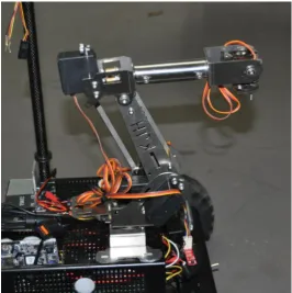
4.4.1 The Six-Axis Robotic Arm
The inclusion of a robotic arm was necessary as it acts as the core mechanism for interacting with the environment.
The main features of the robotic arm which made it ideal for the research project include: Six-Axis (six degrees of freedom)
Constructed from sturdy stainless steel plate Fully waterproof servo motors for axis J1 to J4 Is controllable by Arduino or similar microcontrollers Horizontal reach of 300mm
Vertical reach of 270mm
[image:47.595.164.431.347.615.2]47 | P a g e
4.3.2 Robotic Gripper
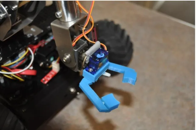
The six-axis robot requires a tool in order to interact with objects. A gripper was designed and created for this purpose and performs the tasks specified in Chapter 6. The gripper is made from ABS (Acrylonitrile-Butadiene-Styrene) by using a 3D printer and is able to be remotely opened and closed by the operator. The three parts of the gripper include:
Left Pincer Right Pincer Servo Housing SG90 Micro Servo
Figure 20: Gripper for the Robotic Arm
The servo box is designed to hold a single SG90 micro servo and allows both the left and right pincer to be attached to the servo box. Each pincer has a gear located at their respective base. The right pincer is controlled form the servo motor between an angle of 0 and 90 degrees. The left pincer moves in synchronisation with right due the meshing of the gears on the bases of the pincer. The open and closed position of the gripper can be seen in Figure 21
48 | P a g e Figure 21: Gripper Open Position
[image:49.595.137.457.389.604.2]49 | P a g e
4.4 Control Panel
A control panel was created to house the electronic components required to operate the six-axis robotic arm. An image of how the electronic components interface with one and other can be found below in Figure 23. The electronic components which have been used to create the control panel are:
2x Arduino Leonardo 1x Arduino Duemilenove 2x Adafruit Motor Shield 7x 10k potentiometers
Miscellaneous components (wire, veroboard, perspex, etc.)
Figure 23: Control Panel
50 | P a g e
The seven 10 kilo-ohm potentiometers act as the physical control for the user to adjust the position of the servo motors. The potentiometers scale a 5V source which is to be converted into a digital value by the microcontroller (0 to 1024). This value is normalised to a value between 0 and 180 which relate to the operating range of 0 to 180 degrees of the servo motor respectively. The value is then written to the servo motor by the microcontroller. Using this method the microcontroller is able to accurately control the position of the servo motor.
[image:51.595.158.436.311.709.2]The potentiometers were used over buttons and joystick, as preliminary testing with the potentiometers revealed that this control method proved to offer ease in making both small incremental and large quick adjustments to the robotic arm‟s position.
51 | P a g e
4.4.1 Control Panel Arduino Code
Below is the Arduino program to operate the Six-Axis Robot by the use of potentiometers. The program controls up to three potentiometers and per microcontroller. Three microcontrollers were used due to the limitation of controlling two KS-3518 servos per motor shield.
/*
Controlling the position of 3 servo motors using potentiometers Author: Jarrad Gleeson
Last Modified: September,2016 */
#include <Servo.h>
Servo myservo; // create servo object to control a servo Servo myservo1; // create servo object to control a servo Servo myservo2; // create servo object to control z servo (claw)
int potpin = 0; // analogue pin used to connect the potentiometer (axis 6) int val; // variable to read the value from the analogue pin
int potpin1 = 1; // analogue pin used to connect the potentiometer (axis 5) int val_1; // variable to read the value from the analogue pin int potpin2 = 2; //analogue pin used to connect the potentiometer (claw) int val_2; //variable to read the values from the analogue pin
void setup() {
myservo.attach(9); // attaches the servo on pin 9 to the servo object myservo1.attach(10); // attaches the servo on pin 10 to the servo object J myservo2.attach(11); //attaches the servo on pin 11 to the servo object }
void loop() {
val = analogRead(potpin); // reads the value of the potentiometer (value between 0 and 1023) val = map(val, 0, 1023, 0, 180); // scale it to use it with the servo (value between 0 and 180)
myservo.write(val); // sets the servo position according to the scaled value
val_1 = analogRead(potpin1) // reads the value of the potentiometer (value between 0 and 1023) val_1 = map(val_1, 0, 1023, 0, 180); // scale it to use it with the servo (value between 0 and 180) myservo1.write(val_1); // sets the servo position according to the scaled value
val_2 = analogRead(potpin2) // reads the value of the potentiometer (value between 0 and 1023) val_2 = map(val_1, 0, 1023, 0, 90); // scale it to use it with the servo (value between 0 and 180) myservo1.write(val_2); // sets the servo position according to the scaled value
52 | P a g e
4.5 Arm Controller
In relation to objective 2, a wearable arm controller was attempted. The intent of the arm controller was to investigate whether the telepresence effect could be improved by providing a more intuitive control method and experience. The main function of the arm controller was to mimic the movement of the user wearing the apparatus and then have the robotic arm produce the same or similar position. By providing a controller method which is able to be controlled more naturally, any evidence of improving the robot control experience was to be investigated by testing with the control along with the traditional control methods.
53 | P a g e
4.5.1 Interfacing Diagram
[image:54.595.139.456.232.544.2]For the arm controller to correctly function, it requires the use of additional microcontrollers which in turn operate the robotic arm. The same microcontroller and potentiometers for the joint were used in both the created segments of the arm controller and the control panel. How the components of the arm controller interface with each other can be seen below in Figure 25.
54 | P a g e
4.4.4 Preliminary Testing
55 | P a g e
Chapter 5
Depth Perception Testing
This chapter covers the experimental testing and investigates the effects of using stereoscopic vision for judging distances. The test has been created to determine if using a VR headset can provide a benefit similar to the natural human depth perception and compare it against a traditional telepresence method of a single camera and monitor arrangement.
5.1 Stereoscopic Depth Perception Test
The stereoscopic vision is a key element of the research and before it can be determined if stereoscopic vision can improve telepresence/ tele-operated robotics, it must first be compared to our own natural vision of the human eye.
56 | P a g e
5.1.1 The Created Test
The primarily objective of testing the user‟s depth perception with the Oculus HMD and the user‟s depth perception without the Oculus HMD is to determine whether the human depth perception is the same as when using the HMD as compared to not.
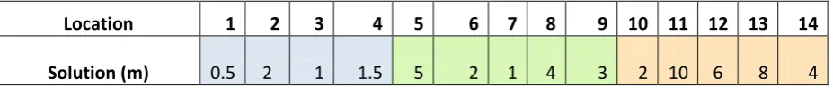
The users/participants have been tasked with judging a object at varying distances. This includes judging small incremental distances up to 2 metres, moderate incremental distances up to 5 metres and large increments in distances up to 10 metres. The same object is to be consistently used for testing with the object placed at the various distances in no specific order.
The distances to be judged are as follows: Small Increments up to 2m:
o 0.5m
o 1m
o 1.5m
o 2m
Moderate Increments up to 5m:
o 1m
o 2m
o 3m
o 4m
o 5m
Large Increments up to 10m:
o 2m
o 4m
o 6m
o 8m
o 10m
57 | P a g e
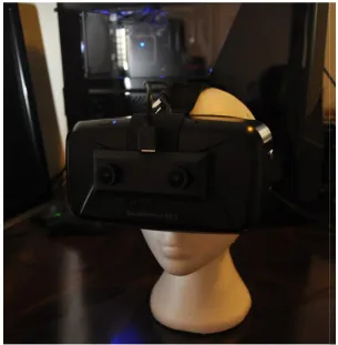
Figure 26 and 27 below show an example of an object (styrofoam head arbitrarily chosen) positioned 5 m away from the user. It near impossible to acquire a sense of the immersion Oculus Rift provides without trying the hardware in person.
Figure 26: Viewing and object 5m away using the Oculus Rift DK2
58 | P a g e
5.1.3 Recording the Results
Due to the large sample population of people performing the test, a reliable and detailed recording plan was created in the form of a test sheet to easily record and track the results from each individual participant. Each participant was provided their own test sheet prior to testing.
A questionnaire was also included on the test sheet to gather information of the user‟s experience with all three methods. Information on preference and opinions of the testing has been reviewed to determine any trends from within the sample population of the individuals who participated in the testing.
5.1.4 Informed Consent Form
59 | P a g e
5.1.5 Stereoscopic Depth Perception Test Preparation
With a significant amount of people involved in the testing of equipment which is unfamiliar to them, it is important that each individual have a clear understanding of the task‟s requirements. Hardware such as the Oculus Rift DK2 and stereoscopic camera are not common knowledge amongst people who do not possess up to date knowledge of technology. As such it is necessary to give a brief overview the device by describing what is, how it works and what it is used for as part of the stereoscopic test preparation.
Before Testing:
1) Familiarise the participant with the Oculus Rift
2) Familiarise the participant with the OVRVision Pro camera module 3) Introduce the 3 different vision methods to the individual
4) Clearly explain the task to the user
5) Provide a copy of the experiment test sheet to each individual which also contains a descriptive explanation on the task
6) Explain how to correctly fill in the test sheet including the questionnaire provided
After Testing:
1) Examine the participant‟s test sheet to ensure it has been completed and assist with any section if the participant does not find the description clear
60 | P a g e
5.1.6 Stereoscopic Depth Perception Test Overview
To successfully test how well participants were able to judge distance, the steps of the Stereoscopic Depth Perception Test were put in place to ensure that the accuracy in the results from the participants was consistent throughout the entire testing phase. All of the steps were designed with a difficulty to allow participants to produce contributable results.
The steps of the test are:
1) Take position at the designated mark
2) Estimate and record the distance of the object for 14 positions 3) Answer the questionnaire provided regarding the testing experience 4) Repeat the test until all 3 vision methods have been tested
The above test is to be repeated using the following vision methods: Natural Vision (Judging distance normally by eye) Stereoscopic Vision (Using the Oculus Rift)
61 | P a g e
5.1.6 Aspects for Investigation
The stereoscopic vision test has been designed to specifically aim at investigating the following:
Depth perception judgement – How accurate are participants able to judge the distances using the three vision methods (natural eye, Oculus Rift, single camera)?
Cyber Sickness- Is cyber sickness affects many participants and the gain insight of the duration of using the headset before it is noticeable?
User Friendliness- Are particular types of vision method easier or worse the others? Does using a particular one give a specific advantage or disadvantage?
62 | P a g e
5.1.7 Hypothesised Results
Prior to performing the Stereoscopic Depth Perception Test, there were some predicted outcomes of the testing, mostly which have been determined from the literature review and experience with the hardware. The hypothesised results of the test were as follows:
An increase in depth perception when using the Oculus Rift DK2 in conjunction with the OVRVision camera module when compared to the single camera and monitor configuration
A decrease in depth perception when using the Oculus Rift DK2.0 in conjunction with the OVRVision camera module when compared to judging the distance by eye naturally without the HMD
A limited time a user/participant can comfortably wear the Oculus Rift HMD before experiencing cyber sickness
63 | P a g e
5.2 Statistical Analysis of Stereoscopic Depth Perception
Of the varying distances tested using the three separate vision methods, the results indicated that there were clear differences in the ability to judge objects at a specific distance. However some methods were better than other within a particular range while others seemed to indicate very little difference at all within those ranges.
5.2.1 Evaluating the Accuracy of the Natural Eye
Using the natural human eye as the only tool to judge the distance of an object is not a difficult task. It is a skill almost every person learns from infancy and is used through the entirety of that person‟s lifetime. As such it provides an excellent basis to compare against in regards to how well a user can judge distances through telepresence.
The data obtained from testing various participants in the experiment can be seen presented below in Table 1 and the solutions for the test presented in Appendix E.
Judging Depth Perception by the Natural Eye Results
Location 1 2 3 4 5 6 7 8 9 10 11 12 13 14
Between 0-2m Between 0-5m Between 0-10m
J. Gleeson 1.5 1 2 0.5 3 4 1 2 5 4 8 6 10 2
J. Winter 1.5 1.5 2 0.5 3 4 1 2 6 4 8 6 10 2
B. Gleeson 1.5 1 2 0.5 3 4 1 2 5 4 8 6 10 2
G. Collins 1.5 1 2 0.5 3 4 1 2 5 4 8 6 9 2
B. Winter 1.5 1 2 0.5 3 4 1 2 5 4 8 6 10 2
D. Winter 2 1 2.5 0.5 3 4 1 2 5 4 10 8 10 2
A. Shephard 2 1.5 2 0.5 3 4 1 2 5 6 8 8 10 2
F. Border 1.5 1 2 0.5 3 4 1.5 2 5 4 10 8 10 2
S. Shephard 1.5 1 2 0.5 3 4 1 2 5 6 10 8 10 2
K. Collins 1 1 2 0.5 3 4 1 2 5 4 8 6 9 2
D. Phillips 1.5 1 2 0.5 3 4 1 2 4 4 8 6 10 2
Table 1: Results from Judging Distance by Eye
Location 1 2 3 4 5 6 7 8 9 10 11 12 13 14
Solution (m) 1.5 1 2 0.5 3 4 1 2 5 4 8 6 10 2
64 | P a g e
Judging the distance an object is located from an individual proved to be an uncompleted process. The majority of participants of the Stereoscopic Depth Perception Test were consistently able to judge the distance correctly. The test featured reasonable increments to cater for the participants whom are not commonly required to judge a specific distance accurately. In doing this, it is possible that this phase of the test may have been too simple to perform well. However it provides a useful indication how well and simply humans are able to judge distances with natural eye sight and provides a target for the monitor and stereoscopic phase of the test.
Location 1 2 3 4 5 6 7 8 9
Between 0-2m Between 0-5m
Correct (%) 72.73 81.82 90.91 100 100 100 90.91 100 81.82
Range (%) 86.37 94.55
Mean (m) 1.55 1.09 2.05 0.5 3 4 1.05 2 5
Solution (m) 1.5 1 2 0.5 3 4 1 2 5
Table 3: General Statistics from Natural Eye Phase
Location 10 11 12 13 14
Between 0-10m
Correct (%) 81.82 72.73 63.64 81.82 100
Range (%) 80
Mean (m) 4.36 8.55 6.73 9.82 2
Solution (m) 4 8 6 10 2
Table 4:General Statistics from Natural Eye Phase Continued
65 | P a g e
5.2.2 Evaluating the Accuracy of the Camera & Monitor
Judging the distance at which an object is located away from a camera by viewing of a traditional monitor proved to be significantly more challenging than simply viewing it in person by eye. A lot of additional information the brain uses to determine what is directly in front of an individual is lost by this method and confirms a significant disadvantage with telepresence. Table 5 below contains the results of the testing during the camera and monitor phase.
Judging Depth Perception by Camera & Monitor Results
Location 1 2 3 4 5 6 7 8 9 10 11 12 13 14
Between 0-2m Between 0-5m Between 0-10m
J. Gleeson 0.5 2 1 1.5 4 2 1 3 2 2 8 6 8 4
J. Winter 0.5 2 1 1.5 5 2 1 4 3 2 8 6 8 4
B. Gleeson 1 2 1 1.5 4 2 1 5 4 2 10 6 8 4
G. Collins 0.5 2 1 1.5 5 3 1 4 3 2 10 6 8 6
B. Winter 0.5 2 1 1.5 5 2 1 4 3 2 10 6 8 4
D. Winter 0.5 2 1 1.5 5 2 1 4 3 2 10 8 10 4
A. Shephard 0.5 2 1 1.5 5 2 1 4 3 2 10 6 8 4
F. Border 2 0.5 1.5 1 3 3 2 1 4 2 10 8 6 2
S. Shephard 0.5 2 1 1.5 4 2 1 5 3 2 8 6 8 4
K. Collins 0.5 2 1.5 2 5 2 1 4 3 2 10 8 10 4
[image:66.595.73.525.271.494.2]D. Phillips 1 2 1 1.5 5 2 1 5 3 2 8 6 8 4
Table 5:Results from Judging by Camera & Monitor
Location 1 2 3 4 5 6 7 8 9 10 11 12 13 14
[image:66.595.68.532.547.596.2]Solution (m) 0.5 2 1 1.5 5 2 1 4 3 2 10 6 8 4
66 | P a g e
Out of the three phases, judging distances via a single camera and monitor setup is the least accurate out of the three methods. This provides further evidence of the disadvantage of typical telepresence.
Location 1 2 3 4 5 6 7 8 9
Between 0-2m Between 0-5m
Correct (%) 72.73 90.9 81.82 81.82 63.64 81.82 90.9 54.55 72.73
Range (%) 81.84 72.73
Mean (m) 0.73 1.86 1.09 1.5 4.55 2.18 1.09 3.91 3.91
Solution (m) 0.5 2 1 1.5 5 2 1 4 3
Table 7: General Statistics from Camera & Monitor Phase
Location 10 11 12 13 14
Between 0-10m
Correct (%) 100 72.73 72.73 72.73 81.82
Range (%) 80
Mean (m) 2 9.27 6.55 8.18 4
Solution (m) 2 10 6 8 4
Table 8: General Statistics from Camera & Monitor Phase Continued
67 | P a g e
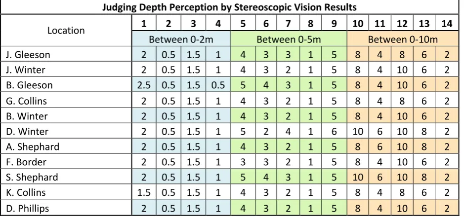
5.2.3 Evaluating the Accuracy using Stereoscopic Vision
Judging Depth Perception by Stereoscopic Vision Results
Location 1 2 3 4 5 6 7 8 9 10 11 12 13 14
Between 0-2m Between 0-5m Between 0-10m
J. Gleeson 2 0.5 1.5 1 4 3 3 1 5 8 4 8 6 2
J. Winter 2 0.5 1.5 1 4 3 2 1 5 8 4 10 6 2
B. Gleeson 2.5 0.5 1.5 0.5 5 4 3 1 5 8 4 10 6 2
G. Collins 2 0.5 1.5 1 4 3 2 1 5 8 4 8 6 2
B. Winter 2 0.5 1.5 1 4 3 2 1 5 8 4 10 6 2
D. Winter 2 0.5 1.5 1 5 2 4 1 6 10 6 10 8 2
A. Shephard 2 0.5 1.5 1 4 3 2 1 5 8 6 10 8 2
F. Border 2 0.5 1.5 1 3 3 2 1 5 8 4 10 6 2
S. Shephard 2 0.5 1.5 1 5 4 3 1 5 10 6 10 8 2
K. Collins 1.5 0.5 1.5 1 4 3 2 1 5 8 4 8 6 2
[image:68.595.65.535.108.329.2]D. Phillips 2 0.5 1.5 1 4 3 2 1 5 8 4 10 6 2
Table 9: Results from Judging by using the Oculus Rift for Stereoscopic Vision
Location 1 2 3 4 5 6 7 8 9 10 11 12 13 14
Solution (m) 2 0.5 1.5 1 4 3 2 1 5 8 4 10 6 2
68 | P a g e
Location 1 2 3 4 5 6 7 8 9
Between 0-2m Between 0-5m
Correct (%) 81.82 100 100 90.91 63.64 72.73 63.64 100 90.91
Range (%) 93.18 78.18
Mean (m) 2 0.5 1.5 0.95 4.18 3.09 2.45 1 5.09
[image:69.595.71.508.71.176.2]Solution (m) 2 0.5 1.5 1 4 3 2 1 5
Table 11: General Statistics from the Stereoscopic Test Phase
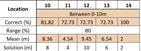
Location 10 11 12 13 14
Between 0-10m
Correct (%) 81.82 72.73 72.73 72.73 100
Range (%) 80
Mean (m) 8.36 4.54 9.45 6.54 2
[image:69.595.73.344.226.325.2]Solution (m) 8 4 10 6 2
69 | P a g e
5.3 Vision Method Accuracy Comparison
The group accuracy is able to be compared to identify which vision method worked most effectively within certain ranges.
Location 1 2 3 4
Between 0-2m
Eye 86.37
[image:70.595.106.367.173.256.2]Camera & monitor 81.84 Stereoscopic Vision 93.18
Table 13:Group Accuracy between 0 & 2m
Location 5 6 7 8 9
Between 0-5m
Eye 94.55
Camera & monitor 72.73
[image:70.595.106.391.305.388.2]Stereoscopic Vision 78.18
Table 14:Group Accuracy between 0 &5m
Location 10 11 12 13 14
Between 0-10m
Eye 80
Camera & monitor 80