Abstract—This paper entails a detailed numerical and
parametric study on the lateral behavior of piles in foundation designs. Single-piles are one of the major components of a foundation as they act as the primary component in the transmission of the weights above the structure into the ground for stability to be attained. For this reason, a detailed study on the influence generated on the p-y curves is mandatory to create a numerically valid model for use in the process of foundation design without much ado. Modelling procedure under consideration employs the use of the finite difference method (FMD) embedded in FLAC2D. FDM is used to implement a solution to the coded input for example soil and pile element parameters. The model validation process done in this paper involves the variation of some of the critical parameters such as the variation on the type of soil in the area under consideration. Next, modification of the elastic modulus of the given soil as a check on the cohesiveness, change on the loading velocity at the top of the pile, a variation of the pile material stiffness and the difference of the pile eccentricity. The results obtained from the p-y curves generated from the parameters undergo sifting through for any effects on the ultimate loading capacity of the pile to the allowed design loading limits upon full structural installation. This variation is necessary for the approval of the validity of the model in engineering design. The parametric study from this study shows that the structure is of functional strength and a tolerable factor of safety.
Index Terms—Finite Difference Method; FLAC2D; Lateral
Load; P-Y Curve; Soil-Pile Interaction
I. INTRODUCTION
The response of laterally loaded piles is a function that is dictated by many related parameters that act upon the pile foundation during loading. At any considerable time of loading, the effects of each parameter input can cause a substantial influence on the reaction of the pile foundation and the adjacent soil components. Engineers always propose pile foundation for the transfer of loads of overlying structures as it offers adequate bearing capacity for lateral loads and also gravity loads. In the past studies on pile foundations, several approaches have been carried out to analyze this response from loads. These approaches include force method, beam on elastic foundation method, soil
Published on October 5, 2018.
A. O. Owino is with Dept. of Environmental Science Graduate School of Bioresources, Mie University, Japan. 1577 Kurimamachiya-chō, Tsu - City, Mie 514-8507, Japan (e-mail: [email protected], [email protected]).
Z. Hossain is with Dept. of Environmental Science Graduate School of Bioresources, Mie University, Japan. 1577 Kurimamachiya-chō, Tsu - City, Mie 514-8507, Japan (e-mail: [email protected]).
J. Shiau is with School of Civil Engineering and Surveying, University of Southern Queensland, Queensland, 37 Sinnathamby Blvd, Springfield Central QLD 4300 Australia (e-mail: [email protected]).
plasticity, and elasticity continuum method. But most recently the practice of finite element method FEM [1], finite difference method FDM [2] is being put in to use. FEM and FDM are flexible and can be manipulated to give a variety of responses and an in-depth analysis of the pile and the soil interface.
The analysis of laterally loaded piles in most cases is expressed mostly by using the load-displacement curve methods also referred to as the p-y curve method. Using the p-y curves, the response of the soil during loading is shown by a series of springs that produce the resistance offered by the load when acting upon them. The curvilinear load-displacement p-y characteristics of the springs are given as input to the analysis, and numerical methods are used to obtain the pile load-displacement response [3]. From the p-y curve obtained, the pile foundations, in this case, the single pile foundation should be able to withstand the imposed load with a reasonable factor of safety, the pile head displacement should not exceed the tolerable movements for the structure it supports, for example, the solar panels in this study and lastly the intermediate soil should not receive excessive stresses that may make it achieve the ultimate load carrying capacity upon full construction and operation [4]. A closer consideration is given on the response of the soil to the short piles as this provides a clear understanding of the pile element because at this depth the displacement is entirely reliant on the resistance of the soil as illustrated by [5].
To obtain a clear picture of the pile responses in this study, the parametric research is necessary to investigate the sensitivity towards fluctuating some of the typical inputs to the program. Klepikov [6], conducted a study to examine the influence generated by the modulus of subgrade reaction at the ground surface as the primary parameter influencing the pile structure response to the soil grid. The subgrade reaction has also enabled the engineer to develop models that can withstand seismic activities without the fear of structural failure as stipulated by [7], who predicted the foundation response to seismic and dynamic loads. As a step to simplify and ease the analysis of pile foundations, 2D and 3D modelling have become handy as it allows for the closer analysis and input of flexible functions that can be executed by any given geotechnical software like FLAC2D using finite difference method. Numerical models have been developed to help comprehend the pile and soil structures [8], to perceive the effect of the parameters to the pile setup when subjected to various modes of loading. This study, therefore, employs the use of FLAC2D in the development of a model to represent the soil and pile interaction and the resultant displacements used to investigate the various parameters discussed in the analysis section.
Parametric Study on the Response of Composite Single
Piles to Lateral Load by Numerical Simulation (FDM)
Vol. 3, No. 10, October 2018
II. FLAC2DFINITE DDIFFERENCE MODELLING PROCEDURE
[image:2.595.320.532.54.175.2]The model was made using FLAC2D which is a sufficient way to solve such complex matters as it gives a clear picture of the performance of the structure for the applied load. By finite difference analysis, a mesh was generated to represent the ground/soil conditions which had fixed grids points with pinned boundary conditions (B) applied along the bottom of the model and roller boundaries (X) on both sides. The final model has been chosen so that the overall velocity field is distributed within the domain and no boundary effect is presented. In general, the model size has to be greater than 2 times the pile length (i.e. 2.8 m radius from pile element axis by 2.8 m depth) as shown in Fig. 1.
[image:2.595.65.273.240.373.2]Fig. 1 Mesh, boundary condition, and pile displacement pattern
Fig. 2 Schematic representation of the grid points and the zones Fig. 2 is a representative of an extended view of the top of the model with 1,2 and 3 indicating the zones and inscribed within the zones (i-1, i, and i+1), shows the stresses involved during stress and stain development process. On the other hand, a, b and c indicated the grid points upon which the velocities are applied to produce deformations that lead to the grid displacement.
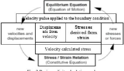
Finite-difference method (FDM) is numerical methods for solving differential equations by approximating them with difference equations, in which finite differences approximate the derivatives. FDMs [9] are thus discretization methods and are the dominant approach to numerical solutions of partial differential equations. FLAC2D applies the FDM to implement a solution to the coded input, for example, the analysis if the pile foundation. FLAC2D therefore, allow for the vector quantities for example forces, velocities and displacements storage in the finite difference grid generated while all scalar quantities, for example, stresses, pressure, and material properties stored in the zone locations. To ensure stability in the numerical scheme, FLAC2D includes the dynamic equations of motion (equilibrium equation) in the formulation. The balance thus provides there is no sudden failure or collapse to the structural component during the lateral loading procedures [10]. The primary explicit calculation cycle is as shown in Fig. 3.
Fig. 3 Basic explicit calculation cycle
The response of a pile element during loading is similar to the elastic model in FLAC2D. Regarding Fig. 2, three main equations that dictate the response of the pile element include Stress-Strain Constitutive Law (Hooke's Law), Equation of Motion for Dynamic Equilibrium (wave equation) and FDM formulation using central finite difference equation as shown in (1), (2) and (3) respectively.
𝜎𝑥𝑥 = 𝐸 𝜕𝑢𝑥
𝜕𝑥 (1)
𝜌𝜕𝑢𝑖
𝜕𝑡 =
𝜕𝜎𝑦̈
𝜕𝑥𝑗 + 𝜌𝑔𝑖 (2)
𝜎̃𝑥𝑥𝑖 (𝑡) = 𝐸
𝑢𝑥𝑖+1(𝑡)−𝑢𝑥𝑖(𝑡)
𝛥𝑥 (3)
Where ρ is the mass density, ux is the velocity component,
E is the elastic modulus, t is the time, xi is the component of the coordinate vector, gi is the component of gravitational acceleration and σ is the component of the stress tensor. Equation 2 illustrates the dynamic force equilibrium which indeed shows the relationship between gravitational forces and the changes in stress in the model grid. As reflected earlier in this paper, FLAC2D consists of mainly useful formulations where the variations in velocity are quickly solved. Consequently, the rate at which strain is experienced in the model grid can be related to the velocity [11]. The finite difference equation for the equation of motion using central finite difference Eqn. 3, can further be simplified and classified into two sections, with the left side of the equation showing the changes in velocity while the right side represents the changes in the stresses involved during the model code execution as shown in Eqn. 4.
(4)
Equation 4 is then rearranged to (5) which upon integration produces the displacements in the grid, (6) and the histogram thereby generated is a plot of the p-y curves of the pile at the prescribed loading velocity.
(5)
[image:2.595.65.272.362.446.2]as pile head displacement variations for two types of soil (silty soil and clayey soil), soil elastic modulus, loading velocity, stiffness of the standard coupling spring represented by the pile element and the pile eccentricity on the p-y curves. The p-y curves will help in the determination of the pile bearing capacity, the factor of safety as well as a step towards the model validation for engineering use in structural design for solar panel foundations.
III. RESULTS AND DISCUSSION
A. Effects Different Soils: Silty Soil and Clay Soils
The type of soil is one of the main parameters to be put into consideration for any construction procedure to be practiced. The cohesive nature of different soils dictates the bearing capacity of the foundation. In addition to bearing capacity, the soil type also dictates the modulus of subgrade reaction, Ks which is a ratio of contact pressure intensity, P and the soil settlement, y. Due to the fact that clayey soil has a higher modulus of subgrade reaction, 80,000 kN/m3, it
attains a higher ultimate load of 15 kN at lower pile head displacement of 4mm as compare to the silty soils (Ks=48,000 kN/m3) that achieves the final pressure at more
massive movements of 10mm as shown in Fig. 4.
A closer examination of the pile element and the soil displacement patterns depicts the more vertical movement of the ground in the clay soil than in the silty soil. This high-intensity soil movement depends on the standard pressure induced by the pressing nature of the pile element as well as the modulus of subgrade reaction, Ks and the displacement,
y produced at the pile head as shown in (7). The soil movements of FLAC2D output are as shown in Fig. 5 and Fig. 6.
[image:3.595.318.535.55.157.2]High-pressure side: P=P*+Kh y (7)
[image:3.595.310.541.381.586.2]Fig. 4 Effects of different soils: Silty soil and clay soils
Fig. 5 Soil-pile displacement patterns for silty soil
Fig. 6 Soil-pile displacement patterns for clayey soil
B. Effects of Soil Elastic Modulus
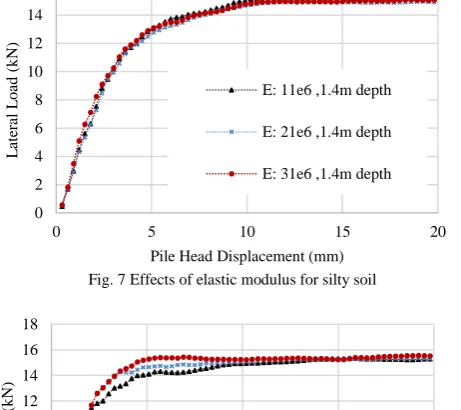
In this case, it’s the elastic modulus of the soil that is studied. The value for the elastic modulus is ranged from 11e6 to 31e6 kPa for silty soils and 40e6 to 60e6 kPa for the clayey soils. The other conditions are held constant as per the design parameters (Pile length= 1.4m, pile diameter=0.13m, the rate of loading force constant). The p-y curves generated from FLAC2D at the design depth shows that the elastic modulus, E, has minimal effects in the silty soils whereas in the clay soils deviations in the ultimate load are noticed at displacements of 5 mm as shown in Fig. 7 and 8. This E variation is a clear indication that the cohesiveness of the soils should be highly considered in the clayey soils if the design bearing capacity is to be achieved.
Fig. 7 Effects of elastic modulus for silty soil
Fig. 8 Effects of elastic modulus for clayey soil
C. Effects of Loading Velocity with Depth on Ultimate Load
Velocity is a time-dependent parameter when incorporated into FLAC2D. It ensures that the deformations on the grid follow the stress/strain law. To achieve the ultimate bearing capacity, the correct loading velocity 0
2 4 6 8 10 12 14 16 18
0 5 10 15 20
L
at
er
al
L
o
ad
(
k
N
)
Pile Head Displacement (mm) silty soil clay soil
0 2 4 6 8 10 12 14 16
0 5 10 15 20
L
at
er
al
L
o
ad
(
k
N
)
Pile Head Displacement (mm) E: 11e6 ,1.4m depth E: 21e6 ,1.4m depth E: 31e6 ,1.4m depth
0 2 4 6 8 10 12 14 16 18
0 5 10 15 20
L
at
er
al
L
o
ad
(
k
N
)
[image:3.595.62.286.489.637.2] [image:3.595.61.279.665.773.2]Vol. 3, No. 10, October 2018
[image:4.595.313.533.146.476.2]should be determined as it plays a significant role in the damping of the equations of motion to provide static or quasi-static also known as inertial solutions. The non-inertial solutions help in achieving the equilibrium state in a numerically stable way with minimal computation effort in FLAC2D. In this study, the velocity was varied from 1.0e7 to 2.5e7 for the single pile foundation depths of 0.7m, 1.4m, and 2.8m. Base on the results, it is evident that increasing the velocity at 0.7m and 1.4m depth increases the ultimate loading capacity in the silty soil, but in the clayey soil, the ultimate loading capacity reduces once the ultimate load is attained at 2.0e7. At the pile depth of 2.8m, increasing the velocity have detrimental effects on the ultimate loading capacity as in both cases (silty and clay soils) there is significant decrease in the ultimate loads as shown in Fig. 9.
Fig. 9 Effects of Loading velocity with depth on ultimate load
D. Effects of Pile Stiffness: Stiffness of Normal Coupling Spring.
In FLAC2D, the coupling springs are a representative of the interaction between the soil and the pile element under consideration. The normal coupling spring is the medium in which the lateral forces applied at the given velocity transmission, occur to the grid at the prescribed location along the pile element nodes. To obtain a desirable ultimate loading capacity of the pile, then the choice of the pile material should also be put on a check. A numerical description of the action of the normal coupling spring stiffness and the displacements produced during loading is as shown in (8).
(8)
Where Fn represents the normal force that develops in the normal coupling spring, csnstiff is the normal coupling spring stiffness, un
p is the displacement of the pile in the axial direction, un
m is the displacement of the grid(soil) normal to the axial direction of the pile, and L is the pile element length.
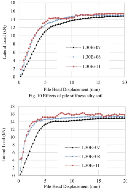
In this study, the stiffness of the normal coupling springs was varied from 1.3e7 kN/m2to 1.3e11 kN/m2with all other parameters held constant (Pile length= 1.4m, pile diameter=0.13m, the rate of loading force constant) for the two types of soils (silty and clayey soils). Based on the
output, it's seen that an increase in the stiffness of the coupling spring increases the ultimate loading capacity of the pile. Clayey soils depict high ultimate loads up to 16 kN at 1.3e11 kN/m2 at minimum displacements 7mm as compared to silty soils at 15kN. Fig. 10 and Fig. 11 shows a plot of the stiffness parameter influence in ultimate loading capacity for silty and clayey soils respectively.
Fig. 10 Effects of pile stiffness silty soil
Fig. 11 Effects of pile stiffness clayey soil
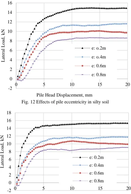
E. Effects of Eccentricity, e
The height of the pile above the ground is an excellent determinant on the moments above the ground level. The moment equilibrium equation is the product of the lateral force and the eccentricity. When the bending moments tend to increase then the ultimate load that the pile element can withstand reduces considerably. This reduction is due to the rotational effect produced by the lateral pressure above the ground level. When this rotational effect cannot be transmitted to the grid, then the pile tends to fail closer to the ground level at minimal lateral loads. In this study, the eccentricity effect is evaluated at 0.2m, 0.4m, 0.6m and 0.8m for both types of soil and the corresponding ultimate load plotted as shown in Fig. 12 and Fig. 13 for silty soil and clayey soil respectively. Based on the results, the eccentricity of 0.2m produced the highest ultimate loading capacity of 15kN in silty soil and 15.8kN in clayey soils. An eccentricity of 0.8m recorded the minimum value of 8.4kN hence this shows that the point of the load applied to a pile is also a strong determinant of the ultimate strength concerning bearing capacity.
0 5 10 15 20 25 30 35 40
0,00E+00 1,00E-07 2,00E-07 3,00E-07
U
lt
imat
e
L
o
ad
(
k
N
)
Loading velocity in FLAC2D
depth 0.7m:silty soil depth 1.4m: silty soil depth 2.8m: silty soil depth 0.7m: clayey soil
depth 1.4m: clayey soil depth 2.8m: clayey soil 0 2 4 6 8 10 12 14 16 18
0 5 10 15 20
L
at
er
al
L
o
ad
(
k
N
)
Pile Head Displacement (mm) 1.30E+07 1.30E+08 1.30E+11
0 2 4 6 8 10 12 14 16 18
0 5 10 15 20
L
at
er
al
L
o
ad
(
k
N
)
[image:4.595.54.279.248.415.2]Fig. 12 Effects of pile eccentricity in silty soil
Fig. 13 Effects of pile eccentricity in clayey soil
IV. CONCLUSION
The primary objective of this study was to evaluate the response of the load transfer curve and the displacements produced. This response shows the influence factor of the lateral load under different circumstances depending on the parameter under study. The parametric study, therefore, acts as a model validation process as it shows clearly the influence produced by a given setting concerning the design value at hand. From this study, it is evident that the integration of the stresses in the grid element around the pile element is an obvious way of understanding the p-y curve characteristics in the soil. The p-y curves further show that during design the soil parameters have a major influence on the projected strength and durability of the foundation. Clay soils gives better lateral capacity than the silty soils with maximum loads of up to 14kN and 12kN respectively.
Additionally, the variation of the parameters such as pile stiffness, loading velocity, and eccentricity have shown that clayey soils have the highest ultimate load bearing capacities of between 15.5kN to 15.8kN at minimal pile displacements of below 5mm. Pile stiffness and the eccentricity play a major role in the determination of the foundation depth hence, should be considered with high precision depending in the load subjected to the foundation. These two factors also influence the type of material to be used in the construction of the pile element.
It is also valid that FLAC2D as a numerical technique in the modelling field is a vital tool for investigating the realistic soil behavior under different conditions and is helpful in simulating all construction sequences concerning the provided design parameters. With the numerical models in place, experimental simulations can be done with lots of accuracy and at a lower cost compared to the procedures involved in the full scale experimental tests in the field.
ACKNOWLEDGMENT
Thanks are also to Japan International Cooperation Agency (JICA) for giving the postgraduate scholarship to the first author
REFERENCES
[1] H. G. Poulos, “The behaviour of laterally loaded piles: I- single piles,” Journal of Solid Mechanics, Foundation Division, ASCE, vol. 97, pp. 711-731, 1971.
[2] D. A. Brown, C. Shie, and M. Kumar, “P-y curves for laterally loaded piles derived from three-dimensional finite element model,” Numerical Models in Geomechanics, NUMOG III, Elsevier Applied Science, 1989, pp.683-690.
[3] W. Cox, and L. Reese, “Pullout Tests of Grouted Piles in Stiff Clay,” Journal of Petroleum Technology, 30(03), 1978, pp.349-356. [4] J. M. Duncan, L.T. Jr. Evans, and P. S. K. Ooi “Lateral Load Analysis
of Single Piles and Drilled Shafts,” Journal of Geotechnical Engineering ASCE, Vol. 120, No. 5, pp.1018- 33, 1994.
[5] B. Broms, The lateral resistance of piles in cohesionless soils. J Soil Mech Found Div, ASCE 90(SM3) 1964, pp. 123–156
[6] S. Klepikov, Calculation of beams on an elastic foundation with a variable modulus of subgrade reaction, Soil Mechanics and Foundation Engineering, 1965, pp.296-299.
[7] C. Caseiro, “Behavior of Elastomeric Materials Under Dynamic Loads,” The Shock and Vibration Digest, 18(1), 1986, pp.3-6. [8] M.W. O’Neill, G. G. Blaney, and G.L. Muster, Behavior of Single
Pile and Pile Group in Overconsolidated Clay Under Relatively Low- Frequency Loading, Fugro-Gulf, Inc., and Univ. of Houston-University Park, 1982.
[9] P.A. Cundall, “Explicit Finite Difference Methods in Geomechanics, in Numerical Methods in Engineering,” Proceedings of the EF Conference on Numerical Methods in Geomechanics, Virginia, pp. 132-150. Vol. 1, Blacksburg, 1976.
[10] A.M. Britto, and M.J. Gunn, Critical State Soil Mechanics via Finite Elements, Chichester U.K: Ellis Horwood Ltd, 1987.
[11] P.K Banerjee, and T.G. Davis, “The behaviour of axially and laterally loaded single piles embedded in non-homogeneous soils,” Geotechnique, 28, No. 3, pp. 309-326, 1978.
Alex Otieno Owino from Kenya, Date of Birth 30th
July 1988 an Agricultural engineer from Egerton university, Degree earned in 2013, Kenya. Currently, doing a Master’s degree in Mie university, Japan on Environmental Science and Technology and scheduled to graduate in March, 2019.
He did summer internship at Asai Nurseries in Japan in September 2018. He previously worked under the Governmental Organization known as National Irrigations Board in Kenya in 2015 as a Graduate agricultural engineer. He is currently pursuing a Master’s Degree in Japan. His research area is in Numerical analysis on composite single pile foundations for the design of solar panel foundations and the responses of the ground during different types of loading with respect to soil conditions and pile properties.
Mr. Alex is a registered Graduate Engineer registered with the Kenya Engineers Registration Board.
-2 0 2 4 6 8 10 12 14 16
0 5 10 15 20
L
at
er
al
L
o
ad
,
k
N
Pile Head Displacement, mm e: o.2m e: o.4m e: 0.6m e: 0.8m
-2 0 2 4 6 8 10 12 14 16 18
0 5 10 15 20
L
at
er
al
L
o
ad
,
k
N