SPEECH RECOGNITION BASED CONTROL AND SMS SYSTEM
SITI FARAH BINTI HUSSIN
This report is submitted in partial fulfillment of the requirements for the award of Bachelor of Electronic Engineering (Computer Engineering) With Honours
Faculty of Electronic and Computer Engineering Universiti Teknikal Malaysia Melaka
UNIVERSTI TEKNIKAL MALAYSIA MELAKA FAKULTI KEJURUTERAAN ELEKTRONIK DAN KEJURUTERAAN KOMPUTER
BORANG PENGESAHAN STATUS LAPORAN
PROJEK SARJANA MUDA II
Tajuk
Projek :
SPEECH RECOGNITION BASED CONTROL AND SMS SYSTEM
Sesi
Pengajian : 2008/2009
Saya SITI FARAH BINTI HUSSIN
……….. (HURUF BESAR)
mengaku membenarkan Laporan Projek Sarjana Muda ini disimpan di Perpustakaan dengan syarat-syarat kegunaan seperti berikut:
1.Laporan adalah hakmilik Universiti Teknikal Malaysia Melaka.
2.Perpustakaan dibenarkan membuat salinan untuk tujuan pengajian sahaja.
3.Perpustakaan dibenarkan membuat salinan laporan ini sebagai bahan pertukaran antara institusi pengajian tinggi.
4.Sila tandakan ( √ ) :
SULIT*
(Mengandungi maklumat yang berdarjah keselamatan atau kepentingan Malaysia seperti yang termaktub di dalam AKTA RAHSIA RASMI 1972)
TERHAD* (Mengandungi maklumat terhad yang telah ditentukan oleh
organisasi/badan di mana penyelidikan dijalankan)
TIDAK TERHAD
Disahkan oleh:
__________________________ ___________________________________
(TANDATANGAN PENULIS) (COP DAN TANDATANGAN PENYELIA)
Alamat Tetap : 3, JLN 2/17, TAMAN SRI KLUANG, 86000, KLUANG, JOHOR.
“I hereby declare that this report is the result of my own work except for quotes as cited in the references.”
“I hereby declare that I have read this thesis and my opinion, it is suitable in term of scope and quality for the purpose of awarding a Bachelor Degree in Electronic
Engineering (Computer Engineering) With Honours.”
Signature : ……… Supervisor’s Name : MR. ZULKIFLI BIN SHARIFF
ACKNOWLEDGEMENT
ABSTRACT
ABSTRAK
TABLE OF CONTENT
CHAPTER TITLE PAGE
TITLE OF THE PROJECT i
DECLARATION iii DEDICATION v
ACKNOWLEDGEMENT vi
ABSTRACT vii ABSTRAK viii TABLE OF CONTENTS ix LIST OF TABLES xiii LIST OF FIGURES xiv LIST OF APPENDIXES xvii
I PROJECT OVERVIEW 1.1 Introduction 1
1.2 Project Objective 2
1.3 Problem Statement 2
1.4 Scope Of Work 2
1.5 Methodology 3
I I LITERATURE REVIEW
2.1 Speech Recognition Jukebox 5
2.1.1 Control Section 6
2.1.2 Logical Structure 7
2.1.3 Program Design 8
2.1.4 Hardware design 9
2.1.4.1 Integration of Hardware Components 9
2.2 SMS Remote Control (SMSrc) 12
2.2.1 Introduction 12
2.2.2 Usage of this system 12
2.2.3 The Hardware 13
2.2.4 Procedure 13
2.3 Relay 16
2.4 Parallel Port 19
2.5 SMTP (Simple Mail Transfer Protocol) 22
2.5.1 The SMTP Model 22
2.5.2 The SMTP Procedures 23
2.5.3 Mail 24
2.5.4 Forwarding 25
2.5.5 Verifying and Expanding 26
2.5.6 Sending and Mailing 26
2.5.7 Opening and Closing 28
III PROJECT METHODOLOGY 3.1 Introduction 29
3.2 Hardware Part 30
3.2.1 Block Diagram 30
3.2.2 Components 32
3.2.2.1Opto-Coupler 32
3.2.2.2 Relay 33
3.3.1 Overview 34
3.4 Matlab 37
3.4.1 Introduction to the Matlab 37
3.4.2 The advantages of the Matlab 39
3.4.3 Matlab Features 39
3.4.4 Matlab 7.8 features 41
3.5 SAPI 42
3.5.1 SAPI 5.1 43
3.6 System Requirement 45
IV RESULT 4.1 Introduction of Controller Circuit 46
4.2 Controller Circuit 47
4.2.1 Circuit Description 48
4.3 Matlab Programming Language and interface 50
4.3.1 'Welcome’ form 50
4.3.2 ‘Authentication’ form 51
4.3.3 ‘Speech’ form 52
V CONCLUSION AND FUTURE WORK RECOMMENDATION 5.1 Discussion 70
5.2 Conclusion 72
5.3 Future Work Recommendation 72
REFERENCES 73
LIST OF TABLE
NO TITLE PAGE
2.1 Voice Commands Recognized by the System 6 2.2 Descriptions of the different bits 21 3.1 The pin numbering and the corresponding functions of
LIST OF FIGURE
NO TITLE PAGE
2.1 Logical Structure of Speech Recognition Jukebox 7
2.2 Diagram of Player State Machine 9
2.3 Overall Schematic of Microphone Circuit 11
2.4 Picture of Microphone Circuit on White Board 11
2.5 Photo of a workable SMS remote control with 4 relays version 12
2.6 Schematic of SMS remote control circuit 13
2.7 Connect the AVR's pins direct to T10s connector 14
2.8 Take +5V DC from SMS remote control board 14
2.9 Remove the <NO> key from T10s and solder an ON- OFF switch in this place 15
2.10 The SMS remote control board (4 relays version) 15
2.11 The PDU decode proccess. Convert them to 8bits by adding one zero at the start of each byte. The PDU format use bytes with 7bit length 16
2.12 The pin outs of DB25 connector 20
2.13 Model for SMTP 23
2.14 Example an error of forwarding process 25
2.15 Connection Opening 28
2.16 Connection Closing 28
3.1 Functional block for the voice detection 29 3.2 Functional block for the whole system 30
3.3 Block Diagram of the Hardware 31
3.4 MCT2E Opto-Coupler IC 32
3.5 Process Model of the system 35
3.6 The logo of the Matlab 7.8 37
4.1 Circuit Diagram of the controller circuit 47
4.2 PCB Layout of the controller circuit 47
4.3 Controller Circuit 49
4.4 Prototype of the hardware that consists of four output 49
4.5 GUI of ‘Welcome’ form 50
4.6 Message appeared if the users choose to terminate the system 51
4.7 The progress bar show the loading of ‘Speech’ Form 51
4.8 GUI of ‘Authentication’ form 51
4.9 The steps to Login 52
4.10 The steps to control ON/OFF by using voice 53
4.11 Details on the steps of control ON/OFF device 53
4.12 Configure microphone and train for the voice detection 54
4.13 The location of Grammar Compiler in Microsoft Speech SDK 5.1 55
4.14 Grammar Compiler Block 55
4.15 XML Grammar File 56
4.16 Compile the XML Grammar File 56
4.17 Location of xml file in cfg format 57
4.18 Command line for recall the XML file in main program 58
4.19 The Operation of The System 59
4.20 GUI for the Initial condition – All devices OFF 60
4.21 GUI of ON condition for Room and Dining 60
4.22 GUI of ON condition for Kitchen, Radio and All Devices 61
4.23 The Matlab program for ON/OFF condition 62
4.24 In switch ON condition for the ROOM 63
4.25 In switch ON condition for the DINING 64
4.26 In switch ON condition for the KITCHEN 64
4.27 In switch ON condition for the RADIO 65
4.28 Notification that send through E-mail if robberies happen 66
4.29 E-mail notification for Dining, Kitchen, Radio and All Devices 67
4.30 The Matlab program for E-mail Notification 68
LIST OF APPENDIXES
NO TITLE PAGE
A Source Code For Form Welcome 73
B Source Code For Form Passcode 78
C Source Code For Form Main 81
D Source Code For Form Recognition / Voice Detection 88
CHAPTER I
PROJECT OVERVIEW
Although, the automatic controller is widely used in traffic controlling, industries and car handling, rarely hear that electrical appliances in the house can be controlled by using voice. Normally, all electrical appliances in a house operate via manual methods by switching on the electrical power supply sockets.
1.1 Introduction
1.2 Project Objective
In order for the project to success and to be implemented, the following objectives have to be achieved:
• To control the home appliances operations by using a voice command. • To monitor whether the electrical appliances ON or OFF by using SMS
(E-mail notification).
• To develop an easier appliance operation system for handicapped user.
1.3 Problem Statement
Nowadays, most of electrical appliances operate via manual methods by switching on the electrical power supply sockets. This technology is not practical for handicapped user. Using this simple speech command, the handicapped can control the electrical appliances easily. Besides, it also can be used as the security system if the robberies happen when the owner leaves the house.
1.4 Scope Of Work
To achieve the project objectives there are certain scope that must been done. The scope can be divided into several parts. The scopes are:
1) This project includes the study of reliability of the software system, which is going to be used to control voice command.
3) After the simulation is done this project will continue with development of the hardware which process need to be plan and the component characteristic need also to be study, such as relay connection and connection between computer and hardware.
4) The way for transmitted and received the SMS need to be studied.
5) The interconnection between hardware system and software system is done based on the function.
1.5 Methodology
This project has been start with research of controlled the electrical devices by using voice. After that continue with developed the GUI for the software system. Then testing the SAPI and Matlab interface with microphone. Design and fabric the PCB layout hardware circuit and etching’s the PCB. Attached components on PCB & complete the circuit. Finally, combined hardware and software and testing the circuit. Check and troubleshoot the circuit if the problem occurred.
1.6 Thesis Outline
This thesis will be divided into 5 chapters to provide the understanding of the whole project.
Chapter 2 describe about the literature review that has been studied to get information to complete the project. This study is focused especially on controlled the electrical devices by using voice and the way for sending SMS.
Chapter 3 it will cover up all the project methodology and a process of this project implementation to achieve goal. Also hardware and software technical details are explained in this part.
Chapter 4 explains the result of this project and the operation of the circuit. In this chapter the analysis of the project also has been discussed.
CHAPTER II
LITERATURE REVIEW
Conducting literature review prior to undertaking research projects was critical as this will provide much needed information on the technology available and methodologies used by other research counterparts around the world on the topic. This chapter provides the summary of literature reviews on key topics related to Speech Recognition Based Control and SMS System.
3.1 Speech Recognition Jukebox
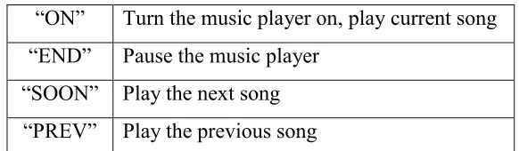
The values of the signal in these different frequency regions helped to determine each individual word’s unique digital ‘fingerprint’. The fingerprints of important words, such as commands for the music-playing element of the design, were stored into the program. Each time a word was spoken, the fingerprint of this sample word was compared to the stored fingerprints to determine which command, if any, was spoken. Recognized commands for the system are:
Table 2.1: Voice Commands Recognized by the System
2.1.1 Control Section
The output of the digital filters would help to formulate a digital ‘fingerprint’ that was unique for each word. Five samples were taken from each digital filter, thus yielding 35 total samples that would comprise the digital fingerprint of each word. The fingerprints of the dictionary words, “ON”, “END”, “PREV”, “SOON”, were stored in the software program. Whenever the user input a command to the system, this sample’s digital fingerprint would be calculated and then compared to each of the dictionary words.
To compare the dictionary words with the sample, the program calculated the correlation of the two vectors. The pair with the highest absolute value correlation was chosen as a match. When an input command word was recognized as a dictionary word, the control section would set a series of flags that would update the
“ON” Turn the music player on, play current song “END” Pause the music player
state machine. This state machine would change state on these flags being set and each state corresponded to a separate song being played.
2.1.5 Logical Structure
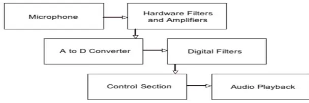
[image:22.595.177.481.477.579.2]The logical structure of the program is quite simple. The user will speak the desired command into the microphone. The microphone will convert this audio signal into an electrical signal, which will then be filtered and amplified before being sent to the A to D converter. The program A to D samples the input, and the output of the A to D converter is run through seven digital filters. The control section uses the outputs of the seven digital filters to obtain a working fingerprint of the spoken command and compares this fingerprint with those stored fingerprints to decipher which command, if any, has been spoken. Upon recognizing a user command, a state machine within the control section will change state. Each state of this state machine corresponds to a separate song being activated. Thus, upon changing state, a different song signal will be sent to the television audio connection, enable music playback. A simple schematic of the logical structure can be found below in Figure 2.1.
Figure 2.1: Logical Structure of Speech Recognition Jukebox
2.1.3 Program Design
interrupt, which runs every 250 µs (4,000 times per second). Atemp was then passed to the seven digital Butterworth filters using a function called setfilters(), which also run in the interrupt. After the filters have been set, the program enters the player() function, which contains the state machine that runs the voice recognition section of the program.
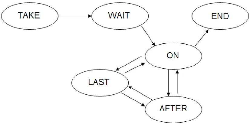
The player() function was broken up into six states: TAKE, WAIT1, ON,
END, AFTER, LAST. The TAKE state was considered to be the off state of the jukebox. When button 7 is pressed on the STK500 board, the player turns on. The user will have to press button 6 to use the voice recognition portion of the state machine. Upon this button being pressed, the state machine was in the WAIT1 state. In this state, the state machine was waiting for the user to say the word “ON.” This signals was send to the state machine that the user wishes to start the player. After the user says “ON,” the state machine enters the ON state and begins playing song 1.
Once in the ON state, the voice recognition state machine has four possible routes. If the user says “SOON,” the state machine assumes the user wants to play the next song (song 2). If the user says “PREV,” the state machine assumes the user wants to play the previous song (song 3). The user can also say “END,” indicating the user wants to pause the playback of the song. Based on whether the user says “SOON”, “PREV”, or “END”, the player state machine enters the AFTER, LAST, or END states, respectively.
Figure 2.2: Diagram of Player State Machine
2.1.4 Hardware design
The human voice is comprised of numerous different frequencies emitted as a compression wave through the air. In order to perform analysis on a vocal sample, this compression wave would need to be transformed into an electrical signal using a microphone. The electrical output of the microphone was filtered and amplified several times in order to produce a clean and responsive voltage signal.
2.1.4.1 Integration of Hardware Components
In order to operate properly, the ground and output connections on the microphone needed to be soldered to two pieces of wire and then connected to the white board. This output connection was connected to a high-pass filter with a 1 kΩ