INVESTIGATION OF STRONG EARTHQUAKE GROUND MOTION
Thesis by
Mihailo Dimitrije Trifunac
In Partial Fulfillment of the Requirements For the Degree of
Doctor of Philosophy
California Institute of Technology Pasadena, Cal if ornia
1969
(Submitted May 20, 1969)
ii
ACKNOWLEDGEMENTS
The author wishes to express his appreciation and sincere gratitude to his advisor, Professor D. E. Hudson, for his inspiring guidance and constant encouragement. He is grateful both to
Professor J. N. Brune for the guidance and help during this investi-gation and to Professor G. W. Housner for encouragement and many helpful discussions. The interest and assistance of Professors
C.R. Allen and C. F. Richter are also appreciated.
iii
ABSTRACT
The pattern of energy release during the Imperial Valley,
California, earthquake of 1940 is studied by analysing the El Centro strong motion seismograph record and records from the Tinemaha seismograph station, 546 km from the epicenter. The earthquake was a multiple event sequence with at least 4 events recorded at El Centro in the first 25 seconds, followed by 9 events recorded in the next 5 minutes. Clear P, S and surface waves were observed on the strong motion record. Although the main part of the earthquake energy was released during the first 15 seconds, some of the later events were as large as M
=
5. 8 and thus are important for earthquake engineering studies. The momen~ calculated using Fourier analysis of surface waves agrees with the moment estimated from field measurements of fault offset after the earthquake. The earthquake engineering sig-nificance of the complex pattern of energy release is discussed. It isconcluded that a cumulative increase in amplitudes of building vibra-tion resulting from the present sequence of shocks would be
signifi-cant only for structures with relatively long natural period of vibra-tion. However, progressive weakening effects may also lead to greater damage for multiple event earthquakes.
iv
part of the high frequency energy. radiated from the nearby earth-quake. to be confined to the layer as a wave guide. The existence of the surface layer will thus increase the rate of the energy transfer into the man-made structures on or near the surface of the layer. Secondly. the surface amplitude of the guided SH waves will decrease if the energy of the wave is essentially confined to the layer an'd if the wave propagates towards an increasing layer thickness. It is also
shown that the constructive interference of SH waves will cause the zeroes and the peaks in the Fourier amplitude spectrum of the surface
I
v
TABLE OF CONTENTS
PART TITLE PAGE
INTRODUCTION 1
I PATTERN OF ENERGY RELEASE DURING THE IMPERIAL VALLEY, CALIFORNIA
EARTHQUAKE OF 1940 3
II RELATIVT!: AMPLITUDES AND SPECTRAL PROPERTIES OF STRONG EARTHQUAKE GROUND MOTION ASSOCIATED WITH HORIZONTALLY PROPAGATING SEISMIC
WAVES 56
APPENDIX I 124
APPENDIX II 138
1
INTRODUCTION
The motivation for a detailed study of strong earthquake ground motion and the related problems which lead to the full under-standing of these phenomena is clearly evident. The importance of a knowledge of the detailed properties and characteristics of strong
'
earthquake ground motion at a given site is obvious to anyone con-cerned with construction of buildings or other structures which must meet "earthquake resistance" requirements. Consequently many studies in this field have been carried out in order to analyze the most important aspects of the problem.
It is convenient to consider· a partition of the studies of strong earthquake ground motion and related phenomena into two groups, according to the order in which they occur in time and equivalently in space. The first group of these studies is concerned with the mechanism of earthquake generation. Here problems related to the pattern of energy release at the source of the seismic energy radia-tion, dimensions and a kind of source, multiplicity of the source, as well as the propagation and radiation patterns may be analyzed. In short one might think of these as the properties of the generalized forcing function, to be applied to the surrounding m~dium, together with the appropriate initial and boundary conditions.
2
3
CHAPTER I
PATTERN OF ENERGY RELEASE DURING THE IMPERIAL VALLEY, CALIFORNIA, EARTHQUAKE OF 1940
A A(t) a(t)
c
*
F(w,t ,6t) f*
f(t) ,f 6t(t) M0
NOMENCLATURE
- area of the fault plane over which slip occurs - envelope of the vibration amplitude
- window amplitude
- Love wave amplitude factor - fault length
- phase velocity
- moving window Fourier spectrum - frequency
- instrument record trace
- seismic moment associated with a double couple source
i TOT
MO-SEISM'MO-SEISM'MO-fie!d - seismic moment of a single event,
p Q T T 0 t
seismic moment of all events, and the total field moment, respectively
- local magnitude estimated using the strong motion instrument
- circular frequency of vibration of a one degree of freedom system
- attenuation constant - period (= 2rr/w)
*
tu
u v
x
Cl
e
6t
p w
4
- center time of moving Fourier window
- time at which the vibration amplitude has decreased to 1/20 of the initial value
- group velocity
- component of the displacement field in
e
direction due to a double couple source- spectral density determined from the record - weighted average of the fault slip
- velocity of source propagation - window amplitude
- characteristic coordinate describing the vibration of a one degree of freedom system
- compressional wave velocity - shear wave velocity
de - angle between u
8 and EW component - strike direction
- source distance - window width
- fraction of the critical damping - rigidity
- density
5
A. INTRODUCTION
In this study records of the Imperial Valley, California earth-quake of 1940 are analyzed to obtain information about the complexity of the source function in time and space. The results of the study
indicate that the Imperial Valley earthquake was characterized by multiple events that occurred in the first 15 seconds and several later events (in the next 5 minutes) which could be called aftershocks, but which, in some cases, were comparable in magnitude to the
I
events in the main sequence. Thus this earthquake, which has often been described in earthquake engineering studies as a typical mod-erate- sized destructive earthquake, had a complicated pattern of energy release. Numerous examples of a complex pattern of energy release for larger earthquakes may be found in the literature
(Florensov and Solonenko, 1963; Wyss and Brune, 1967; among
*
others).
The Imperial Valley earthquake centered along a well defined fault, and after the earthquake the fault offset was documented in detail (Buwalda, unpublished field notes; Richter, 1958). This allows estimation of the moment from field evidence, and thus gives an inde-pendent check on the r,esults obtained from the instrumental records. The first portion of the El Centro strong motion accelerogram used in this study has a special significance for earthquake engineering, since, considering both duration and amplitude, it is the strongest earthquake ground motion yet recorded.
Documentation of the pattern of energy release is important for
6
engineering applications first because the duration and character of the shaking are the important facto;i:-s controlling damage in structures. Secondly, the distance between the source of major energy release and a given structure is also closely related to damage.
B. DESCRIPTION OF THE IMPERIAL FAULT
The Imperial fault is a northwest trending fault of the San Andreas fault system in southern California. It was discovered as a result of the earthquake of 1940 (Buwalda and Richter, 1958) al-though the existence of a major structural break along this line is also indicated by geophysical evidence (Biehler et al. , 1964) as
.
---well as by the existence of a pronounced scarp at the northwestern end.
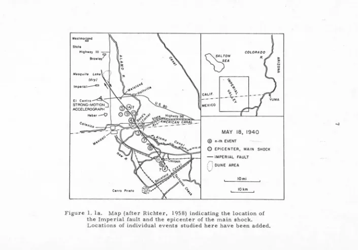
The recent motion along the fault has been almost pure right lateral strike-slip. The fault trace is nearly straight (Figure 1.1 a) except close to the northern end where t~e fault curves and branches and has a small amount of dip slip. Th) amount of right lateral
Westmorland Cl State
HiQhwo1 Ill
l3
Browley(dr1J Imperial--=
El Centro~ STRONG-MOTION
::i
ACCELEROGRAPHl>
,..
l> ~0
Cerro Prieto
~;ON
VEA
~ -<I
<"11
""
,,~~:.I~.
-1-
-
-
-
4-}
MEXICO ~
MAY 18, 1940 @ n-th EVENT
0
EPICENTER, MAIN SHOCK- IMPERIAL FAULT
(.\ DUNE AREA
'"
IOmi
IOkm
Figure 1. la. Map (after Richter, 1958) indicating the location of the Imperial fault and the epicenter of the main shock.
Locations of individual events studied here have been added.
J> :II N
0
z J>
Figure 1, 1b. Aerial photo of the Imperial fault taken shortly after the 1940 earthquake. The orange grove in this photograph lies south of the Cole Road near the point on the fault nearest to Bonds Corner.
9
trace are given in Figures 1.1 a and 1. 1 b. The map is modified after Richter ( 1958}. The aerial photo was taken shortly after the 1940 earthquake.
C. EPICENTER OF THE MAIN SHOCK AND AFTERSHOCKS
Because all close stations were on one side of the epicenter of the main shock, the epicenter could not be determined very accurately.
The epicenter given in Richter (1958} is indicated in Figure 1.1a. Concerning the epicenter of the aftershocks, Richter (1958} may be quoted: 11
• • • the epicenter of the afters hock at 9: 53 p. m. on May 18 cannot be located instrumentally with the desirable precision, nor can any of the immediate aftershocks. Nearly all the large aftershocks were later members of bursts of successive earthquakes, of which the first were too small to be clearly recorded, while the later ones were large enough to confuse the recording of the following largest shocks
10
D. INTERPRETATION OF THE EL CENTRO
STRONG MOTION RECORD
In order to investigate the nature of energy release in this
earthquake the El Centro strong motion records for the first 6 minutes
after the instrument was triggered were studied. It is of interest to
note that the usually reproduced "standard" accelerogram used for
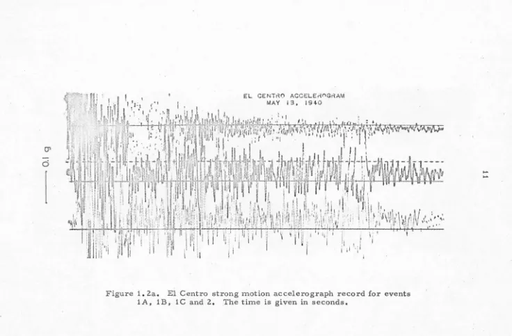
many engineering investigations {Figure 1. 2a) consists only of the
first 30 seconds, including the first four shocks and omitting later
also significant events. The resolution of individual events in a
complicated pattern of energy release depends critically on the
distance of the recording station {because of dispersion) and the
fre-quency of the waves analyzed. For this reason the high frefre-quency
strong motion recording close to the source of the energy release is
of great importance for this work. Clearly recorded P and S waves,
and in most cases, surface waves, were observed for ·several events.
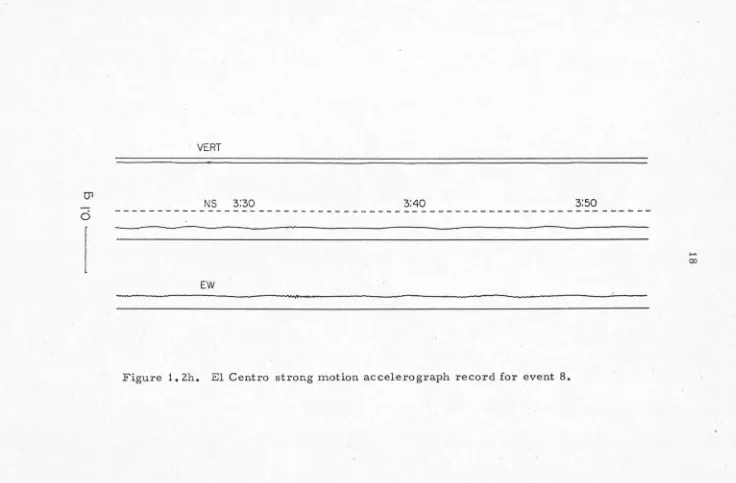
These events are shown in Figure 1. 2a to Figure 1. 2k. The P wave
arrives with large amplitudes on the vertical component and is
followed a few seconds later by the S wave which arrives with strong
amplitudes on the NS and EW components. Several seconds after the
S wave a long period {- 2 cps) surface wave can clearly be seen for
most events. The S wave amplitudes for events after the first 25
seconds are smaller than those for the earlier events, but when a
distance correction for amplitudes is made {distance is estimated
from the S-P times) it is found that the magnitudes of some of these
01
d
~· H''!_; "1
n
l •!
1 EL CENTNO ACCELErtf'IGNAMf:.g 'It.,,, ·.· . C· :
i~
~~1I 1 I ' . , . 'I
MA y I 3 • I 9 4 0 .' ~ ! I -1 ,. I
J {' :· _. ft"j 1:'fi~~ 1 l • 1 • I ' I f . t
'·l' ·;
·
d
Hi
-
'
.
1 11' .,.~
•1,1
~
J \ ,/J
,!
II '
'
·,I,
i ' : ; .• " I I ' " . : " --~
"
... :. ''. ... · .. t1.l 1.f.,f. ..·t
...
~I
',;: · ';1
-
1
l!
l
~
l
1~
r,,l
·
1~~,;
~
:
li
~°l
':~j~{)1L1
.,
1:!
1.1
:
~
"
'
.
'
'd
11 i"1~
1
11
1
111ii:
;
•
;"
'
'
"'
.. '
. •i"''I~ ., 'I ",
. '·'
. ~l i··;,,,..~ l j l· , .' , r!
, 1I ·' i I 1., ., I . '1 '• ' ' I . ' ' ( , " · ' .'I
l •.
r ...
q . ~ ;· 1 ;ii;;1, . ···i z11r114 ,•W, ;-:;1·" .r '.: -• , •• :, I . !: ' 11 r . •I
I
J ~ l: ·--1 f IL ~ i~ \ . . ~ I ' . I I '1 I
Ji
•
.1
wd.
·'
.
:
·
J
;·
I
d1¥
,
,J!111
·J
J
J1..
J
:
.
_I
J_u_
-I.I-"
"
-L·---·
!2fll·&\
. ,
f;:
,·
ii 11:1111iilclb
1
r:i
.
h~:
h~''tu~~1
·!11:~1
1
u'
f
1~
l~I"
·11 •lm ;'
·
'i\
r
r1t1!51~Uri
:
,
~w
(Nrtr111
tY'm
\
11:f1l1
'
n
1
i
i
.
I
1 :
1
rfi1
f
i
r
t
,Nf
i
.. i ,
1 , , 1 i::1 . ,
r
~
1 . I;1
.
:
.
1t
I
.
.
,
:
.
..
l
1, I • 1 r ,. : !1 .:.
1
11
.
1
~
1
1 \ 1
'
.\
,t
.\
l1
:: :·
·
:
!!
il'.
111il
1
.
'
I ,\ I'1
:<
111!1il
ii:!
ill.
':
li
l
:'1(,\1:1
IH
11 ;:1
1
,
.
1
1.: I
:!L
,· I .1
.
\
I
!.;'.•qi I~
; • •~
·L l ,r . ~. J ',. I Ir
i '·
,
:.···:.!,'', '/ !·,•1 I ·. \ ., .'' •i ' I 1• 1.,!j .. ~·.l' , n!i ',,
I ~:• , ·.' / '·.' :I 1 '< ·, 1:,1r·,I ., .. ' : ' , ,,:i'i '.'~,1·1: , .. ,,, .. 1, , .. : :' ,. •• < I' I.
,
'
,
.. ::.
~
-rr.7,:'.
·
;,;:t,·,,;,
.
111
·
·::.
·
:: :,1·
1
;·
·
i
:l
1
'
I
::
\ I I!~
::
1
\1'
1'' 11! i I: I \; ' 1 .,.... . 111 I
I
'
.
·
'
'
'li' "II
JI I' I I I I 1I
II
I Il
i ,i . : . l ·' ~1111 ,. : ii I ,:1.:1'
1
·
III
'I II
l
~ ~ 'I I • I .I
l
''''I 'If I~ Il ''
I' ,,, ' 1 · I ' I:: : : I 1
1
'
:
1
:,
l
'1 ~I I! : I I I I I,
,
I
J:i /'l
L 1 \ :1 IFigure 1. 2a. El Centro strong motion accelerograph record for events
1A, 1B, 1C and 2. The time is given in seconds.
El CENTRO ACCELEROGRAM
.
I
.
VERT MAY 18 1940 .hA \
\
h
Bhe
12
.
11
'
11,\U
I
1
11
,
1
II
I
\
.
2
~
.
l . \I
. .
~
.
Ns . .
'? . . .
.
.
'~
.
. . .
2? . • • .
~s
• .
"~~ ~
~
·
~~\
. 'I
~~~,1~~~~~~~~~1
IA
Is
le
2
Figure 1. 2b. Replotted El Centro strong motion accelero graph record for events 1 A, 1 B, 1 C and 2. For better readability of the record the gain is reduced
by the factor of 2. 10.
...
tJ1
d
VERT
- - - -- - - - -- -
-0:40
NS
0:50 1:00EW
Figure 1. 2c. El Centro strong motion accelerograph record for event 3.
1:10
...
01
d
VERT
~ ~·~1::;::=~~~~-;::::~::::::::::::::::==::::~;;;;;;:====:::::::;:;::::::::::===:::::::::::::::
NS 1:30 1:40
EW
Figure 1. 2d. El Centro strong motion accelerograph record for event 4.
...
0"1
d
VERT
1:40
NS
1:50 2:00EW
Figure 1. 2e. El Centro strong motion accelerograph record for event 5.
...
01
d
VERT
NS 2:10 2:20 2:30
EW
Figure 1. 2£. El Centro strong motion accelerograph record for event 6.
01
d
VERT
NS 2:40 2:50
EW
Figure 1. 2g. El Centro strong motion accelerograph record for event 7. 3:00
....
01
d
· VERT
NS 3:30 3:40 3:50
---EW
Figure 1. 2h. El Centro strong motion accelerograph record for event 8.
l'.J1
d
VERT
4:00 N"S __
-i;-J
4:10 4:20 4:30- -
-
-
-
-
--
-
- -
-
-
- -
-
-~~-
-
- --
- -
-
-
-
-
--
-
- -
-_-_-
- - -
-~---- ~---
-_
-
-
- - -
--
-
-
-
-
-
-
-
-
-. -' l"l
Figure 1. 2i. El Centro strong motion accelerograph record for event 9.
,_..
01
d
NS 4:50 5:00
---EW
Figure 1. 2j. El Centro strong motion accelerograph record for event 10.
N
01
d
VERT
Figure 1. 2k. El Centro strong motion accelerograph record for event 11.
N
22
largest event (event 2), and are thus important in earthquake engi-neering studies.
Because of large amplitudes, high frequency oscillations, and trace overlap, the original El Centro strong motion record (Fig. 1. 2a) is confusing. To improve readability of this record all three traces were digitized and replotted at reduced gain in Figure 1. 2b. Although this record appears complicated, when it is com-pared with aftershock events (e.g., event 9 in Fig. 1. 2i), similar wave forms can be recognized. Higher frequency phases on EW and NS components represent S waves from the more or less distinct events. At least four S arrivals corresponding to events designated 1A, 1B, 1C and 2 can b'e seen in Figure 1. 2b. Corresponding P wave arrivals for each of these events cannot be unequivocally identified because of the constant high level of the short period pulsations caused by all preceding events. Probable P wave arrivals for these events are indicated in Figure 1. 2b by an arrow.
In order to interpret the phases recorded in Figure 1. 2a to Figure 1. 2k, travel time curves and dispersion curves were
23
Layer thickness (km) a (km/sec)
p
(km/sec) p (gr /cm ) 31 0.18 1.70 0.98 1. 28
2 0.55 1 •. 96 1. 13 1.36
3 0.98 2. 71 1. 57 1.59
4 1.19 3.76 2.17 1. 91
5 2. 68 4.69 2. 71 2.19
6 00 6.40 3.70 2. 71
Poisson's constant was taken to be 1/4. Densities in the last column were calculated using the empirical relationship of Birch (1961)
p = O. 770
+
0.302aDispersion curves calculated for this model (Figure 1. 3) show the group velocities for the first four Love and Rayleigh modes. The flat character of the fundamental mode curves indicate that most of the energy in the period range O. 5 to 5.0 seconds will travel with a velocity of about 1 km/sec.
The epicentral distances of each event were determined from the P and S wave arrival times on the El Centro strong motion seis-mogram. These distances were checked against the surface wave arrival times. Using only arrival times at one station it is not pos-sible to determine the position of each event; however, if it is
u fl) ~ E ~ >-" ... 4.0
3.0 I
)
u 2.0
0 ..J w > a. :J 0 a:: (!) ) 1.0 0
. .
J
D
rv
""'
-3
24
I
I
I
I
I
v
~
/
/
' - -
.----... -.-3/_
1£
~--·
2I -'
---
---,
_,~
"'""
-
--
_,
_,
-
---
____
..
- LOVE WAVES- - - RAYLEIGH WAVES
2 3 4 5
PERIOD, seconds
Figure 1. 3. Love and Rayleigh wave dispersion curves for the structure
corresponding to the Westmoreland profile (Biehler, 1964) in the
Imperial Valley.
N
25
assumption that the epicenters of all events lie alo.ng the surface
trace of the fault to the southeast cannot be strictly justified, but
appears to be a reasonable first approximation. Certainly the locus
of the main energy release events must lie near the observed fault
trace. Aftershocks of large earthquakes also usually cluster around
the fault rupture and some recent studies of precisely located
after-shocks indicate that most of the events lie very close to the fault
trace (Parkfield, 1966; Eaton, 1967; Borrego Mountain Earthquake,
1968; Hamilton et al., 1969). The fact that the observed fault offset
(Figure 1. 9) increased towards the southeast and that the biggest
displacements were recorded close to the international boundary
sug-gests that most of the energy release took place SE of El Centro.
The main energy release and fault rupture appears to be represented
by the first 25 seconds of the strong motion record (Figure 1. 2a).
As mentioned earlier the identification of P wave arrivals for the 4
events on this section of the record is rather uncertain because the P
waves are less pulse-like than the S waves and are variable in relative
amplitude (e.g. , compare the various events in Figure 1. 2c to 1. 2k).
Because of the complexity of this section of the record several other
sma1le r events could have occurred and not been identified. The
longer period pulses on the NS and EW components arriving at about
4 and 11 seconds are probably surface waves corresponding to events
1 A and 1 B, respectively. The excitation of 2 cps surface waves is
variable, in some cases a prominent surface wave pulse is observed
26
is probably related to variations in the depth of the events. The S
wave for event 2, probably the largest event of the series, arrived
some 24 seconds after the first event. The P wave time and
there-fore the distance of this event is somewhat uncertain but is probably
as indicated in Figure 1. 2b, which would place the event at the
south-easternmost part of the break, similar to event 6 {Figure 1. 2f) and
event 11 {Figure 1. 2k). The El Centro strong motion record is
interpreted to indicate that the main fault rupture occurred along a
section of the fault from near the initial epicenter southeast to near
Cocapah in a series of more or less discrete events which occurred
in a time span of about 15 seconds and are represented on the first
25 seconds of the record.
Event 2 might be called a "stopping phase" in the sense that it
probably represents the last event in a series of events successively
further toward the southeast, but probably does not represent a
stopping phase in the idealized sense for perfect interference as
described by Savage {1965).
Magnitudes have been assigned to the various events using the
definition of local earthquake magnitude (Richter, 1958) and the strong
motion re co rd {Figure 1 o 2a to Figure 1 o 2k). This is not a completely
correct procedure for determining ML because the local magnitude ·
is defined in terms of the maximum amplitude on records from
standard Wood-Anderson torsion seismometers rather than a strong
motion instrument. Amplitudes were estimated for 2 cps waves which
would give the maximum deflections on the Wood-Anderson instruments
approxi-27
mate the local magnitudes which would have been deterrnined on a
Wood-Anderson type instrument at El Centro and are given in Table 1.
Table 1
Magnitudes for Events in the Imperial Valley Earthquake of 1940
Event Distance (km) MS.M.
L.
ML1A 7-15 ? 5.7-5.9
1B 17-23? 5.6-5.8
1C 13-19? 5.4-5.6
2 35-44 ? 6.2-6.4 6.3
3 20-28 4.9-5.3
4 13-19 4.4-4.5
5 8-12 4.5
6 34-43 5.4-5.5
7 25-34 4.8-5.2
8 24-32 4.2-4.4
9 13-19 5.2-5.3 5.2
10 14-29 4.7-4.8
11 33-43 5.8-5.9 4.8
The local magnitude of ML = 6. 3 for the main shock was determined
by taking the grand average from EW and NS components of the
Wood-Anderson seismograph records at Tinemaha, Haiwee, Mt. Wilson,
Pasadena and Santa Barbara and EW component at Riverside (see
28
strong motion instrument. Magnitudes ML = 5. 2 for event 9 and ML = 4. 8 for event 11 were computed from the EW and NS records from Mt. Wilson and the EW component from Riverside. ML for event 9 agrees closely with the determination from the strong motion instrument; however event 11 gives a magnitude almost one unit higher on the strong motion instrument than on the Wood-Anderson instrument at large distances. The spectrum of this event is obviously quite different than that of event 9.
E.
ANALYSIS OF DISTANT RECORDSFourier Spectrum, F(w,t ,6t), of the Tmemaha Records
*
.
In a simple Fourier analysis of the complete record, infor-mation on the time dependence of the incoming wave forms, i.e., the time of their arrivals, duration, and dispersion properties are not directly displayed. Therefore, the following form of moving window Fourier analysis is used:
where
*
soo
-iwt*
F(w,t 6t) = e f6 t(t) dt-oo
0 t ::: t
*
- 2
6tf(t)a(t); t * -
~t
< t :s; t * +~t
0 t>t*+6t 2
29
the function f{t) m ultiplied by the window of the form:
0
a{t)
0 so that
*
t < t*
It is evident that F(w, t • .6t) can be used for sever al purposes.
*
For example• if the time coordinate t is taken as the travel time•
*
.
then for a given distance, F{w,t ,.6t) yields the dispersion properties of the incoming waves. In addition, for complicated records, in par-ticular. records of multiple event earthquakes• F(w, t , .6t) can be
*
used to separate different events or different phases. The choice of .6t, i.e.• the window width (as well as the window shape), depends on the particular needs of the analysis• and has to be chosen in each case to suit the physical character of the function f(t) to be analyzed.In this work only a square window• a(t) = 1. 0, is used. To
*
analyze the record f(t) • a discrete set of w., i = 1, 2, ••• ,n and t.,1 J
j
=
1, 2, ••• , m, together with .6t are chosen. If w. are chosen, 1*
F(w.,t.,.6t).
1 . 1 · for n and m large enough, will 1 J
i= , ••• ,
n; J= , ••• ,
m*
approximate a continuous function F(w, t , .6t). Equally spaced w. 's l
*
*
and t. 's and linearly interpolated F(w,t ,.6t) between the discrete J
30
Several .6t intervals were used during the course of the work in
order to study the properties of F(w, t
*,
.6t). The final window widthwas chosen to be .6t
=
O. 7S min and increments in t* were taken as1/8 min. F(w,t* ,.6t) was plotted using a Calcomp plotter (Figure 1.4a
*
to Figure 1. Sb). Each plot represents F(w., t. , .6t).
1 . 1
l J i= , ••• , n;J= , ••• , m
for an interval of one minute and for the frequency range from 10 to
7S rad/min (periods 3S to S sec). All plots were normalized, each
with respect to the maximum peak value that occurred in that 1 min
time interval, so that spectral values range from 0 to 1. 0 of that peak
value. The interval from 0 to 1. 0 was subdivided into 20 levels.
Levels of value greater than O. S were connected with full contour
lines in order to clearly display the peaks in the spectrum.
Figure 1. 4a and 1. 4b give the spectra obtained for the EW
com-ponent at Tinemaha. The spectra are not corrected for the
instru-ment response; however, such correction would not critically alter
their appearance. Time on these figures corresponds to the time on
Figure 1.
6
and is measured in minutes from an arbitrary point atwhich the record digitization was initiated.
An aftershock, herein called the Brawley even (Figure 1. 7,
19 May 1940, S:S1 GCT, M
=
S.S), was used as an example of asimple event and the spectrum was computed and plotted (Figure
1. Sa, Figure 1. Sb) in the same manner as for the main event. As
can be seen in Figure 1. Sa and Figure 1. Sb the spectrum corresponds
to a slightly dispersed train of waves lasting for about 1/2 min with
Figure
.,,
i:> c 0~
12 I/ <----TINEMAHA EW COMPONENT
PEAK VALUE
=
344.00 mm sec..c:::._ ....,,,
---
.
-
-
- -
:::::..
/ / "'-,,
/
-
--=--==--
-
---- ---- __.::::=-- ::::- - - ,, - - =-: , / / .--:;....
./
--...=::
- -
'
~ ~-:;:=-:::.--
_ _..,...,.. _,,,.~'
.... --=
-
~
-I t I
:>
~
-_::::-,
v / , -=:.=
-- -- ... - - - , ... ~ ~. I I ""'--~ - ' ..._ ____
- - -
__..-...
-
/ -
- =-
....- ,.,.,
...-·---,----~---
-
- -
===-
---
/
---
-:-:=::-
~
--=-==--- -
-
/ / -::__.; - ~ ~ ..._--
---
-/ /--
~---
- -,,,.--
,.· /__.,..,.
___,
'-/ '-I
<--~..- /
,,...
\J
----~
----=-c::::
.
-
,c:_-_ _~ - I L . . _ - - --.-=:::::--
-1.3
*
1.4a. Moving window Fourier spectrum F(w,t .~t) for the Tinemaha EW seismogram of the Imperial Valley Earthquake of 1940.
w
-TINEMAHA EW COMPONENT
PEAK VALUE = 343.50 mm sec
I - - I ,____. / V ,,--.
-
---
-'----
. _ . /---
~ ~
-....__
-
~/ /'
--
---- =-
-=::::::::;:..- - ' ...-
-
-
-
--
::::::----
__...:::_ --==--
-
--= - --
----7'----=--=----=-
--
-
...
\ \ ~
--
-
--
---
---,
....-\ \
~-
-..:::: - - - . : '"':.. • - _..,.,,,. / ,,,,-... , I /- = - - - -- --"- _.,..,,. / ' '
-....,,,_.
~-
--==
-
-.::::-
'-
r - - - -_;;;:::::;;.- ---:::::=--,
\ , , ~ 1 I --:::.---/--•
~
I ' ' ,'-'""'-==-...-
~-
_ £~
-._:: --en , / - -- - - - ... - - -.:::--
--===---
·
~
----
-i
•
~~~~~~~~~
--
'.----~-
-
--
-
~-~
-
~~~---~-;
/
~~)
z
.
--::::
'
-
~-~~
~
·---
-
---
-00 ~==~
~~~==-
-----··-:.:=-=~~-=~
~~ )}
-=~
~
~
·
"'.'~ "~ ~-
/
~
~:~
-:-:__ -
~~
.
.
;c
~
12 '-.. ' / // - ----. ... .- - ...:::::--
~
/ :....:::::::.-- --- =- - =.
~
, ,, r /.> ...__ :
,
-- - --:::_ '
' -/--, ,--..--_::::_
·
-
---:---=-
-
_ _, ' _, ---- ---- --=
~
~.
...-::: ...
;;-
_,..,,.. ~-
\ /,__,.. \ ) - _ ./ ~ L
-- -- -- -- I I ~- '
-/ '
~-
-
-
--_...,..,
~ / _'
/
> / --:;....--
--
-'-/
1.4 1.5 1.6 1.7 1.8 1.9 2.0 2.1 2.2 2.3
TIME, minutes
*
Figure 1. 4b. Moving window Fourier spectrum F(w, t , 6t) for the Tinemaha EW seismogram of the Imperial Valley Earthquake of 1940.
6
"' 7
1:>
c 0
~ 8
"'
0 0 ~ 10a.. /\ ~
<
__,
I ··-./ / ' ,. ,.,..-0.5 ( I ' -,...--TINEMAHA EW COMPONENT
PEAK VALUE = 20.45 mm sec
BRAWLEY EVENT
/\ \ \ \--, · .. : , ~ ~ ~_,__1.---· -- ..;,-... .---..
-\ -\
\
' ' \
\
\ \
....r
---:-=:-~- --
_
;._ ...
' \
'
." \ / ,,,/ / ,,-...----
---
...'
.
,
' i I I I I I - - "" ... ,,,. ,, . . : . . . . _ - - - - -...
\ I
--.1 0.6 / I1 ' ' ' _ , / - V' .
. I \ ' • ' ' ' - --::::: - ___.-
::::=-...--
'-._
\.
.
\
.
'
-=--::
-I \ ' ''· '· ' \ / _,..,,. -·-.::::--,-: -;-I i /\. ' ', .._ '-'::_-=._ - -~
'
/
~
~
• y / ,,,/ / ... ~ - ~--... '-.... \... \
\ \
'
~ ' ' ' " \ \ "' / -... ...) 'v(~'\•11 1••"..::_ ---;7-,,~\\I
I
--
'
I I - / .. • \ , _,,,. - ... ,, ... ; . .. ~--7_ - - ' \.
...,
- - ___ ...
--==----~ t /1 1 1---~ ~
... ~---
-
-
/
__...<
'
--
,
'
...,.,.
-
~
/:...---, ) / / · - - - =--:::__,-·I,.-~
-,,:::-~-' ,,
--
~ .. /,,, .,..._
_-:=-:-I
I
J ) ... /,...- - ~-:--~-~-~-_;,._-;,/' , .
,
/ I.
/ 2 ; :
_,
,,.-
-::::.=:::::=--
---__:-A~---:::::=::-----
-.r-
/ - - J. r ••:::----·<::::: •
I I I ) I I .I / ;:/;;;.': - ·- - · · -- "-r-
-r - ' ,/
_.
1
1.JJ
1
~/
~
~-:
~-;
I ._/,.... " · :111
!( ./
,
:.__
~-. -~'i'//"'--- I ) .· ' __ ,.1111
w:'/"",.
·
·
,-
I <.... __,."/
/~
----:· .../ / / I I '.
(.~
·
\
'\_-~~
::-::::;_ -~_>
_,)$
./ t' ( I I• l ' ~~--___ .::;:.:..._-.-- '>
/ I / \ \ ' \ -~ ' - - - -·/ / .
' . .. ...,. ~.__-- ~ ,,
I ,. - .• - -- ~ --.::.:_~~ '-..._
_,..--- _,..--- .
-
-
-
.
~"
.,.,....-- _ /'
' '
'
'-.::---
_____....1 I / ..--- , --:_...,.. - - - .... '...,~
.
/
/ "''
', / -
. -
___
-
-
-
:_!-' .
_
__ -
_ -
--~ ..
'
/ ' .0.7 0.8 0.9 1.0 I. I 1.2 1.3
TIME, minutes
Figure 1. 5a. Moving window Fourier spectrum F(w, t *,tit) for the Tinemaha EW seismogram of the Brawley event (19 May 1940, 5:51 GCT).
11'1
"O
5
~
,__
TINEMAHA EW COMPONENT
PEAK VALUE
=
20.45 mm secBRAWLEY EVENT
----::::-
~y
/ " ' - . . ! : : : = - - I f \ \-
~ ('
... ', ,.' I- ~
I -,_... __...,.. - ...-_.,,. . . / -
-\ ;.. / -... ,,,. ~ - A ' , / / ~
1.5 ',
> / / ,,
r__.... _... _,..,. ,,.-- -.. :._::.,, (" #" V/ ./ -==---::---::;::::- ~ -
-=::::::--~ ...-: :::::-/ ... --=-/ --- ,,,. /\ ~I ---... '
'
/__,,
/ I"
>~
;;:-
_
:'
--... ,,,.,,.._I
'
/ /,_
----/ '-'
\ ;:;;-· --
-
·-
'-/·- -
-
-=---
,.--
,
I...-I
-/ -<-
/ ,~
/ /
---
,,.---
----
,I--
--
---
--
..._ ~'- / \ ...
-1.6 1.7 1.8 1.9 2.0 2.1 2.2
TIME, minutes
----~
..._
*
Figure 1. Sb. Moving window Fourier spectrum F(w, t , 6t) for the Tinemaha EW seismogram of the Brawley event (19 May 1940, 5:51 GCT).
w
800- Tl NEMAHA EW COMPONENT
400- I . GROUND ACCELERATION
~
0
-·
.
~~·~rl!
:1
~
·1
,:f
,
1
!'
MJ!J/.:i·f~}#dJ~
1
1
~~1~
A
A
~I
A
•.
~
.A
Mr
1
~~
.A~.,/,.It.
M.A.l\u1if\~
,,
'
'\
~Ii
1ll
'
1
rj
r,
·
lrl~!
I
,~~1/f''(l'fJ'~'n
f\.J '.Ji''""'llllJ \fW'J<r400-
I
.
t t I I I I I • I t I I I I I I I 4 5
' ' ' ' 2 . 3
000-• 0 1 minutes
cm
-..-min
9 - ~ GROUND VELOCITY
4- .
r
M~:-··Jif
V
V
~fv!{VJ\fif'J\N0\f~Vv\i'vv'lf\,vvv
--~ ~ .
8-' I I I I I I I I I I I I I I I I I I I I I I I I
O 1 2 · minutes 3 4 5
1 '2
2-
1
1
GROUND DISPLACEMENTI
\
3 4 5 6 1 8 9I-
J\
\
·
~
Vl l
l
l
l
.
l
mm
~:
.,/
\{J
V
v\f
;/
\
l\N
\
AN\J
\
;1fl}V\rvvv\/
\
n
A
/\f
"./"
2- ,1
' '
0 1 2 minutes 3 4 5
Figure 1. 6. Calculated EW ground acceleration, velocity and displacements at Tinemaha for the Imperial Valley Earthquake, 1940. Arrows indicate expected arrival time for events as inferred from the El Centro strong motion seismogram.
w
36
TINEMAHA EW COMPONENT
BRAWLEY EVENT
150-150-'
2-~
~~
AfLA
min ~"Y''
I-2-'
1.0-l
1.0-'
minutes
minutes
minutes
GROUND ACCELERATION
I I
2 3
GROUND VELOCITY
I I
2 3
GROUND DISPLACEMENT
I I
2 3
37
made for a recording from the Haiwee Wood-Anderson instrument showed essentially the same features. The location of Tinemaha (9 = 8°) and Haiwee (9 = 4°) are such that EW motion represents essentially pure Love waves.
Integrated and Filtered Distant Records
The Tinemaha EW components of the Wood-Anderson records of both the Brawley event (Figure 1. 7) and the main sequence (Figure
1. 6) were corrected to give true ground acceleration as a function of time. The instrument constants used for the instrument correction were: V s
=
2800, T = 0.8 sec, and ~=
1.0. The corrected ground motion was then filtered to eliminate periods greater than approxi-mately 30 sec. This was done because of possible uncertaintiesre-sulting from the data processing procedures and the large instru-mental correction necessary.
38
Interpretation of Distant Records
Comparison of the Fourier amplitude spectra for the Brawley
event (Figure 1.5a, Figure 1.5b) and the main sequence (Figure 1.4a
and 1. 4b} or a comparison of the calculated ground motion on Figure
1. 6 and Figure 1. 7 illustrates the complexity of the main earthquake.
If all the source parameters associated with each of the multiple
events were similar to the Brawley event and if there were sufficient
time intervals between successive events so that interference would
be negligible, it would be possible to identify all individual events on
a long period ground motion record such as in Figure 1. 6 by simply
identifying a "characteristic 11 peak (e.g., indicated by an arrow in
Figure 1. 7). However, this is not the case for the Tinemaha record
of the Imperial Valley Earthquake. As can be seen from the calculated
ground motion (Figure 1. 6, Figure 1. 7) and Fourier spectra (Figure
1. 4a and Figure 1. 4b} the predominant period of waves recorded at
Tinemaha was about 10 seconds. The duration of the surface wave
train for a single event, e.g., the Brawley event is about 30 seconds
or 3 cycles of a ten second period wave. This makes it difficult to
resolve events separated by less than 30 seconds. Arrows numbered
1 to 9 in Figure 1. 6 are spaced to represent the relative arrival times
predicted at Tinemaha. The arrows on the basis of the approximate
locations indicated by numbers 1A, 1B, •••• 11(Figure1.la) have
been time shifted as a group to give the best agreement with the first
pulse of energy. Number 1 in Figure 1. 6 stands for the group of
events 1 A , 1 B , and 1 C.
can-39
not be resolved by the long period (- 10 sec) surface waves recorded
at Tinemaha. These waves thus combine to give approximately the
effect of a source propagating to the southeast. The· shape of the
Fourier spectra corresponding to these events (Figures 1. 4a and
1. 4b) is consistent with this interpretation as is the Tinemaha ground
motion record which can be explained as a superposition of several
pulses shaped like the single pulse from the Brawley event. This
interpretation is also supported by the difference of 0. 8 on the Richter
magnitude scale, between the local stations (ML = 6. 30) located
mainly NW from El Centro and teles eismic stations (MS
=
7 .1)located E and SE, suggesting independently that during the main
energy release the source propagated towards the SE.
Local magnitudes
M~
0 M., estimated above from the strongmotion record at El Centro suggest that events 3,
6,
7,9
and 11might have been large enough to generate significant long-period
energy. The prolonged train of surface waves on the EW component
of ground motion at the Tinemaha station (Figure 1. 6) show
long-period (- 10 sec) wave arrivals which might be associated with these
events. However, filtered records from other local stations (Hai wee,
Mt. Wilson,· Pasadena, Riverside) show no coherent pattern associ
-ated with these events. This suggests that the prolonged train of
surface waves consists of scattered reflections from crustal
inhomo-geneities that have been generated by the main events (first 15 seconds)
but travelled indirect reflected paths to the seismograph station.
Figure 1. 8 gives low-pass filtered records (corner period
!\
2
:I
"'
Tl NEMAHA
PASADENA
(j.- 546 KM.
(j.- 440 KM.
~
(j.- 294 KM.
!l...J\n~
ti
MT. WILSON ll- 290 KM.!j
RIVERSIDE (j.- 224 KM.0
I
2
I 3 I 4 I
.
~
.
6
I
MINUTES
Figure 1. 8. Surface waves from Imperial Valley Earthquake, California, 1940
recorded on low-pass filtered EW .seismograms from Wood-Anderson
instrument at Tinemaha, Haiwee, Mt. Wilson and Riverside, and on the low magnification long-period torsion record from Pasadena.
7 I
~
41
so that a surface wave traveling with a velocity of 3. 5 km/sec arrives
at the same time on all records. Although there is no coherent
pat-tern, it is obvious that the "coda" of surface waves is longer and
more complex than that following the Brawley (single-event) earthquake.
This may have, in part, resulted from the greater relative excitation
of long-period surface waves by the main events since the "coda"
con-sists of primarily longer period waves. It is quite possible that the
largest of these events (e.g., nos. 6,
9,
and 11) generated surfacewaves that could have been clearly observed if it had not been for the
large amplitudes of the scattered surface waves from the first part of
the rupture. The magnitudes of these events were unusually large for
ordinary aftershocks. According to Bath's law (Richter, 1958) the
magnitude of the largest aftershock is usually about 1. 2 less than the
main event. Thus, although the main energy release during this
earthquake probably occurred in the first 15 seconds, significant
energy release occurred as late as event 11 some 5 minutes later.
It is also possible that significant long-period energy continued to be
radiated after the first 15 seconds in some complex manner not simply
related to the inferred magnitudes of events 2 to 11. That there may
be considerable variation in the ratio of long-period to short-period
excitation is indicated by an inspection of the various aftershocks, in
particular, events
9
and 11.The relatively great excitation of high frequencies for event 9,
suggests that it may have been deeper than events 6 and 11, assuming
that deeper shocks occur under higher stress and thus generate higher
difference between MS. M.
=
L
42
5.8- 5.9 and ML= 4.8 for event 11.
F. FIELD OBSERVATIONS OF FAULT OFFSET
Figure 1. 9 shows the amount of right -lateral offset along the
Imperial fault as it was observed in the field shortly after the May 19,
1940 earthquake (Buwalda, unpublished field notes). The pattern of
these offsets indicates that the main part of the displacement took
place along a surface fracture some 20 to 25 km long extending
approximately from the instrumentally determined epicenter of the
main shock SE some 5 km past Cocopah (Figure 1. 1 a). Tentative
location of the main sequence of the events 1A, 1B, 1C and 2 (Figure
1. 1 a), or an "equivalent 11
propagating rupture towards SE along the
same section of the fault, are in agreement with the observed surface
displacement (Figure 1. 9). In addition, the distribution of the set of
nine aftershocks (Figure 1. 1a) also supports the conclusion that the
main energy release took place 'along the same 20 to 25 km section of
the fault. The observed fault offset (Figure 1. 9) NW of the
instru-mentally determined epicenter (Figure 1. 1a} is probably associated
with the Brawley event, as suggested by Richter (1958). Repeated
surveying of the Imperial fault since 1940 indicates (Brune and Allen,
1967) that there has been c~_eep along the northwestern part of the
fault trace. On March 4, 1966 there was a low-magnitude earthquake
(M = 3. 6) with surface faulting along 10 km of the fault trace, centered
about the point nearest to El Centro, the same northwestern part of
20,
5 MILES
I
f-
15
w
~
0 w
I
~w
~
..J0
~ -'
-'
[
~
4
>
z
~
lj~
d
0•
!z
10
....
:IE %.t
•
•
i
l
'
w
(
~!
w
•
0
.
ex ..J
5
•
LAI ~~
!
4(a..
•
.J \)
•
-'Cl)
(
'
0
••
••
..
'
•
DISTANCE ALONG IMPERIAL FAULT
HORIZONTAL DISPLACEMENTS ON IMPERIAL FAULT - MAY 18, 1940
Figure 1. 9. Plot of the relative displacements along the fault trace as measured in the field by J. P. Buwalda (original notebook and some additional data were kindly supplied by Prof. C. R. Allen). Vertical lines indicate the range of the observed displacements at essentially same locality.
~
44
(Brune and Allen, 1967). The Borrego mountain, California, earth-quake of 9 April 1968 (M
.
=
6. 5) triggered creep episodes on several fault systems including the Imperial fault. Theodolite resurveys(Allen, et al. , 1968) indicate 1. 2 cm cumulative right lateral dis-placement at the point where highway 80 crosses the Imperial fault (Figure 1. 1a), 1.1 cm 6 km northwest, and 1. 3 cm 11 km northwest from the same locality. These new triggered breaks along the
Imperial fault extended for more than 20 km in the same region as the small earthquake of 1966 (Brune and Allen, 1967). Allen,- Brune and Lomnitz (personal communication) did not find any evidence of recent fault slippage at either the locality of the All American Canal (Figure 1. 1a) or in the vicinity of Cocopah as of January 1969. The recent activity along the northwestern part of the Imperial fault sug-gests that it is behaving at present differently than the section
south-east of the epicenter of the 1940 earthquake. This difference could perhaps be related to the fact that the NW part of the fault did not slip as much as the SE section during the May 19, 1940 earthquake, but was rather fractured by the later aftershock activity, fault creep or both, and remained in a higher state of strain.
G. COMPUTATION OF SOURCE MOM.ENT USING SEISMIC WAVES
45
M
0 • ../2rrD.Cw •
where
x
=
~~ (~
-
cos e)0
To take into account the attenuation of the waves due to scattering and anelasticity {together with other sources of the energy loss), and to correct for the angle 5 of the EW component relative to
de
the ue direction., the following expression can be written: '1Tl:l
OUT
0
---
1cos 0
= ue
where u is the spectral density determined from the record.
In the case of a multiple event earthquake where the individual events are sufficiently separated in time, the moment may be calcu-lated as the sum of the moments associated with each event. If each
1
such moment is denoted by MO-SEJSM'
The sequence of 4 events that occurred in the first 25 seconds of the onset of the strong motion record were too closely spaced for this condition to apply to waves of about 10 seconds period recorded at Tinemaha. For these waves, the multiple events behave more like a propagating source.
46
length and the propagation velocity. From the plot of displacements
(Figure 1. 9) and the distribution of aftershocks shown in Figure 1.1a,
the main rupture appears to have extended from the epicenter to
Cocopah, a distance of about 20-25 km. The rupture velocity is
approximately given by the fault length divided by the time difference
between the triggering of the strong motion instrument and the origin
time of the last event, about 15 seconds. This gives an effective
rupture velocity of about 2 km/sec. Estimates of the source
param-eters (b = 20 - 25 km, v::::: 2 km/sec, C::::: 3.4 km/sec at T
=
11 sec,0
and cos 9
= -
O. 99) give an approximate value forx
to be 4. S to5. 0 and
Is~
XI -
O. 20 which is in approximate agreement with theshape of the spectrum given in Figure 1. 4a as indicated by spectral
gaps at periods of about 9 and 1 S seconds. With the a:bove assump-tions one obtains
26
at Tinemaha: MO-SEISM::::: 1.1 * 10 dyne-cm
at Haiwee: MO-SEISM::::: 1.3*10 26 dyne-cm
In these calculations the following values were used: Q::::: 200;
-1a
I
AL
=
O. 91 * 10 cm dyne; T0 = 11 sec; RT
=
ground amplitude0
in microns/trace amplitude in millimeters = 60; C
=
3. 7 km/sec;6
=
546 km for Tinemaha; 6=
440 km for Haiwee; oHAIWEE=
31°;0
OTINEM.
=
27 • These two determinations are regarded to be ingood agreement considering the difficulty in the interpretation and
47
H. COMPUTATION OF MOMENT FROM FIELD OBSERVATIONS The computation of the moment from field observations was performed using the well known relation (Maruyama. 1963; Aki. 1966; Brune and Allen. 1967):
MO-field =
u
µAFrom the field evidence the average displacement along the
complete fault length measured on the surface of the ground was 1. 25 m. The fault length was about 65 km (Richter, 1958). The depth of the faulting was estimated to be about 7 km by fitting the geodetic data given by Byerly and DeNoyer (1958) with the theoretical curve for a strike-slip fault taken from Knopoff (1958). With µ = 3. 3 X 10¹¹ dyne/ cm 2, one obtains £or the whole fault plane
3 25 26
MO-field=
4
X 1. 25 X 3.3 XO. 7 X 6.5 X 10 = 1.4 X 10 dyne-cmHowever, if the northwestern section of the fault did not slip during the main event. but later during the Brawley event as suggested above, then the field moment for the main event should be calculated from the southern section only.
Taking the length of the fault section corresponding to the main propagating rupture to be about 25 km fault depth of 7 km and the average displacement of 2. 7 meters corresponding to the fault
section between the All American Canal and Cocopah. one obtains essentially the same moment:
3 25 26
48
The moment estimated from the field evidence would be
expected to be somewhat larger than that estimated from the seismic
results because the field observations include fault slippage occurring
during later aftershocks as well as creep. Considering the
uncer-tainties involved in both the field data and the seismic analysis, the
agreement is remarkable.
I. MAGNITUDE AND MOMENT
The published magnitude for the Imperial Valley
earthquake of 1940 is 6. 7 (Richter, 1958). However,
a strictly objective determination of magnitude using
Wood-Anderson torsion seismometer records gives a value of
6.
3. Themagnitude indicated from the strong motion instrument is also
6.
3.It was originally felt that more weight should be given to distant
stations in the assignment of 6. 7 as the magnitude. The magnitude
*
ML=
6.
3 is obtained from the average of magnitudes determinedusing maximum deflections on EW and NS Wood-Anderson components
at stations Tinemaha, Hai wee, M;:. Wilson, Pasadena, Santa Barbara,
and Riverside as shown in Table 2. The period of these deflections is
about 1 sec.
*
By definition, ML = log A - log A0 where A is the amplitude in mm of the trace recorded by a standard Wood-Anderson torsion seis-mometer (V = 2800, T = 0.8 sec,
s
= 0.8) at a distance of 100 km from the epicenter, and A0 is the amplitude with which the same instrument would record an earthquake of magnitude zero, at this distance. The magnitude defined in this way is a measure of the largest amplitude of ground motion at a given distance. Determina-tion of magnitude in this manner is not considered reliable at disTABLE
2
Data Used in Determining the Local Magnitude ML For the Imperial Valley Earthquake of
1940
Station Direction Distance Distance Station maxA log A M
(km_) Correction Correction (mm)
--
EW50.5
1. 70
6.3
Tinemaha
546
4.8
-0.2
NS
79
1.90
6.5
EW
-110
2.04
6. 6
Hai wee
440
4.6
o.
NS
-125
2.1
6.7
~'°
EW
103
2.02
5.9
Riverside
NS
224
3.7
+o. 2
EW
<143
2.16
6.2
Mt. Wilson
290
4.0
NS
<149
2.17
6.2
EW
90.5
1.96
6.2
Pasadena
294
4.0
+0.2
NS
?> 79.5
1. 90
6.1
EW
> 85
1.92
6.3
Santa Barbara