UNIVERSITI TEKNIKAL MALAYSIA MELAKA
FABRICATION OF AUTOMATIC PUMP DOWN ON SPLIT
UNIT WALL MOUNTED TYPE AIRCONDITIONING SYSTEM
This report submitted in accordance with requirement of the Universiti Teknikal Malaysia Melaka (UTeM) for the Bachelor of Mechanical Engineering Technology
(Refrigeration and Air Conditioning System) with Honours.
by
MUHAMAD ASRUL AFFENDI BIN MAT NOR B071310002
820731-08-5831
UNIVERSITI TEKNIKAL MALAYSIA MELAKA
BORANG PENGESAHAN STATUS LAPORAN PROJEK SARJANA MUDA
TAJUK: FABRICATION OF AUTOMATIC PUMP DOWN ON SPLIT UNIT WALL
MOUNTED TYPE AIR CONDITIONING SYSTEM
SESI PENGAJIAN: 2016/17 Semester 1
Saya MUHAMAD ASRUL AFFENDI BIN MAT NOR
mengaku membenarkan Laporan PSM ini disimpan di Perpustakaan Universiti Teknikal Malaysia Melaka (UTeM) dengan syarat-syarat kegunaan seperti berikut: 1. Laporan PSM adalah hak milik Universiti Teknikal Malaysia Melaka dan penulis. 2. Perpustakaan Universiti Teknikal Malaysia Melaka dibenarkan membuat salinan
untuk tujuan pengajian sahaja dengan izin penulis.
3. Perpustakaan dibenarkan membuat salinan laporan PSM ini sebagai bahan pertukaran antara institusi pengajian tinggi.
4. **Sila tandakan ( )
SULIT
TERHAD
TIDAK TERHAD
(Mengandungi maklumat yang berdarjah keselamatan atau kepentingan Malaysia sebagaimana yang termaktub dalam AKTA RAHSIA RASMI 1972)
(Mengandungi maklumat TERHAD yang telah ditentukan oleh organisasi/badan di mana penyelidikan dijalankan)
______________________ Alamat Tetap:
NO.14 JALAN JENARIS E
TAMAN JENARIS
43000 KAJANG,SELANGOR
Tarikh: ________________________
Disahkan oleh:
________________________
Cop Rasmi:
Tarikh: _______________________
DECLARATION
I hereby, declared this report entitled “Fabrication of Automatic Pump Down on Split Unit Wall Mounted Type Air Conditioning system” is the results of my own research
except as cited in references.
Signature :
Name : MUHAMAD ASRUL AFFENDI BIN MAT NOR
APPROVAL
This report is submitted to the Faculty of Engineering Technology of UTeM as a partial fulfillment of the requirements for the degree of Bachelor of Mechanical Engineering Technology (Refrigeration and Air Conditioning System) with Honours. The member of the supervisory is as follow:
……….
Mohd Farid Bin Ismail
(Project Supervisor)
………
Muhammad Fairuz Bin Abu Bakar
i
ABSTRAK
ii
ABSTRACT
iii
DEDICATION
For my beloved wife and child
JAMIAH BINTI ISMAIL MUHAMAD HARIS ZAYAN QASEH HARISHTA ZAYANI
Special dedicated to my supervisors
MR MOHD FARID BIN ISMAIL
iv
ACKNOWLEDGEMENT
In the name of Allah S.W.T, the most gracious and merciful, praise to Allah the lord of universe and may blessing and peace of Allah be upon his messenger Muhammad S.A.W. First, and foremost thank to Allah for giving me wellness and ideas to do this project. Without any of it, I surely cannot complete this project in the time given.
I would like to express my deepest gratitude towards to both my project supervisors Mr. Mohd Farid Bin Ismail and Mr. Muhammad Fairuz Bin Abu Bakar as well as every lecturers, for help and guides your brilliant advices, guidance time encouragement and patient during the time period of completing this project help me a lot.
v
TABLE OF CONTENT
Abstrak i
Abstract ii
Dedication iii
Acknowledgement iv
Table of Content v
List of Tables ix
List of Figures x
CHAPTER 1: INTRODUCTION 1.0 Project Background 1
1.1 Problem Statement 1
1.3 Objective 3
1.4 Scope 3
1.5 Proposed Solutions 4
CHAPTER 2: LITERATURE REVIEW 2.0 Introduction 5
2.1 The use of split unit type AC in industries 5
2.2 Refrigerant leak 6
2.3 Impact of refrigerant leak 9
2.3.1 Environment 9
2.3.2 Ozone 10
2.3.3 Global warming 11
2.4 The study of type of Automatic Pump Down of The refrigeration and Air conditioning system 12
2.4.1 Commercial refrigerator and Air conditioning Industry 12
vi
2.4.3 Medium temperature Walk-in Cooler 14
2.5 Summary Literature Review 15
CHAPTER 3: METHODOLOGY 3.0 Introduction 16
3.1 Flowchart 16
3.1.1 Design selection 18
3.1.1.1 Selection of system 19
3.1.1.2 Proposed design 20
3.1.1.3 Bill of material 23
3.1.1.4 Material selection 24
3.1.2 Fabrication 26
3.1.2.1 Modification of outdoor unit 27
3.1.2.2 Wiring connection 28
3.1.2.3 Installation 28
3.1.2.4 Vacuum 29
3.1.2.5 Charge refrigerant 29
3.1.3 Analysis 30
3.1.3.1 Setup the experiment 31
3.1.3.2 Run the experiment 31
3.1.3.3 Testing experiment/ Project 32
3.1.3.4 Obtain the data 33
3.2 Summary 32
CHAPTER 4: RESULT AND DISCUSSION 4.0 Introduction 33
4.1 Operations system 33
4.2 Data Collection 34
4.3 Specification recommendation by manufacturing equipment 35
4.3.1 Specification outdoor unit air conditioning 35
vii
4.3.3 Specification Low Pressure Switch 36
4.4 Data analysis 37
4.4.1 Result Current, Time process pump down, Amount refrigerant balance versus Pressure switch setting 37
4.4.2 Pressure switch set at 110 Psi 38
4.4.3 Pressure switch set at 95 Psi 39
4.4.4 Pressure switch set 80 Psi 40 39
4.4.5 Time at pressure switch set 90 Psi 85 Psi 40
4.4.6 Conclusion 40
4.5 Discussion 4.5.1 Pressure switch set 110 Psi 40
4.5.2 Pressure switch set 95 psi 41
4.5.3 Pressure switch set 80 psi 41
4.5.4 Conclusion 42
4.6 Limitation 43
4.7 Problem face during project 43
CHAPTER 5: CONCLUSION AND RECOMMENDATION 5.0 Conclusion 44
5.1 Recommendation of project 46
REFFERENCES 47
APPENDICES
A Table worksheet progress of fabrication Figure process cutting, Brazing and Flaring B Figure wiring connection outdoor unit
Figure installation air conditioning at testing bay Figure vacuum system
viii Figure run experiment
Figure charge refrigerant use weight scale
D Figure observation pressure refrigerant and current electric. Table result data experiment 1
E Table result data experiment 2 Table result data experiment 3 F Table result data experiment 4 Table result data experiment 5 G Table result data experiment 6
ix
LIST OF TABLES
3.1 Product structure for this project 23
4.2 Specification outdoor unit air conditioning 35 4.3 Specification Solenoid valve 36 4.4 Specification Pressure switch 36 4.5 Summary data result from experiment 1 to 7 37
x
LIST OF FIGURE
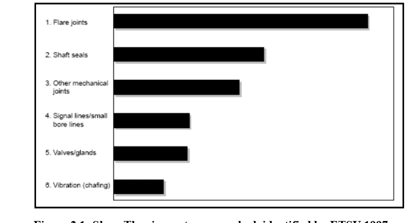
2.1 The six common leak identified by ETSU 1997 7
2.2 Show comparison of RAC system fault type two companies 8
2.3 The refrigerant is trapped between the compressor and discharge valve and the main valve system is pump down 12
2.4 Example installation refrigerant gas detection City Multi VRF Automatic pump down 14
3.1 Flowchart methodology 17
3.2 Flow chart for design selection 18
3.3 Out unit used 20
3.4 Indoor unit used 20
3.5 Schematic drawing for modification of out unit 21
3.6 Wiring diagram of modification or outdoor unit 22
3.7 Low pressure switch used this project 25
3.8 Solenoid valve use on project 26
3.9 Flow chart fabrication process 27
3.14 Flow chart of process experiment and collecting data 30
4.5 Current, Time and Amount refrigerant balance between Pressure Switch Setting 38
1
CHAPTER 1
INTRODUCTION
1.0 Project Background
The air conditioning system must be free leakage conditions to operate due to refrigerant only acts as a heat transfer agent, a close cycle system is needed to control the pressure and avoid operating system in abnormal conditions. For example, leaking of refrigerant gas is mixed with air cause hazarded. There are many occasion of refrigerant leakage of refrigerant on split type AC system. The leakage may happen between pipes and component connection cause by poor installation or wear and tear process. A prevention system need to be design to avoid the refrigerant leakage because refrigerant leakage may create several problem to the environment and the people directly.
1.2 Problem Statement
2 lower operating efficiency in the system. The leakage of refrigerant may also give bad impact to the compressor.
Compressor is an important component in air-conditioning systems. If the system is having a leakage, the compressor will be jammed and the ampere will be high. Due to lack of gas, compressor work harder which causes the compressor jammed. This is because the compressor has not any refrigerant to compress. According (Rodriguez 1995) stated that ‘An undercharged condition creates a higher than normal superheat as well as lower sub cooling. This can have an adverse effect on compressor motor winding .Refrigerant undercharging also decreases the system capacity’. This can have an adverse effect on compressor motor winding. The loss of the refrigerant in the compressor will cause the compressor operate high vibration and noise, and become to be damaged. When the compressor operates low pressure refrigerant, the compressor will be damaged. Furthermore, the high expenditure will be incurred according to the damaged compressor with including the labor cost to change the new compressor. Limited knowledge in air-conditioning possibility maintenance cost may also higher. From experiences while performing servicing work, there are number of users which want to add refrigerant into the system. In the same time, the refrigerant is usually not reduced in the system. From this situation, they have limited knowledge about the content of refrigerant in the system. Because of this, the possibility of high cost maintenance will occurred. Refrigerant leakage contribute to ozone depletion and global warming.
3 depleting refrigerant and global warming. Refrigerant leaks from the system will reduce the efficiency of the system and the ozone depletion and global warming. Impact global warming can be climate change.
1.3 Objective
The aim of this project is to build system trigger leakage and automatically pump down the refrigerant in system. In order to archive this aim 3 objective were set. There are:
i. To design and select fabricated automatic pump down system that is attached to wall mounted AC split unit.
ii. To install automatically pump down as a solutions for refrigerant leakage and save refrigerant in the system.
iii. To analyze capability of the system in different condition.
1.4 Scope
4
1.5 Proposed Solutions
5
CHAPTER 2 LITERATURE REVIEW
2.0 Introduction
A split system is an air-conditioning system that uses refrigerant as the heat exchange fluid and has an evaporator, compressor, and condenser as separate components the air conditioning system is split. The system is uses the refrigerant as the heat exchange liquid and have the evaporator, compressor, and condenser as a separate component. There are many commercial applications, compressor, condenser, capillary tube and placed into a space piece equipment called outdoor unit. Refrigerant pipe, which is specially designed for connect to system components between indoor and outdoor units. The evaporator is located on the indoor unit and the compressor, evaporator and capillary tube are the components of outdoor units. The outdoor units usually installed at the outside of the building.
2.1 The use of split type AC in industries
6 cooling load on the central system of the building such as a hospital, Split unit air conditioners is used. The split system air-conditioning units is a complement to the central air-conditioning system existing in the building. For this project using 600 grams of refrigerant in the air conditioning split unit 1 hp wall mounted type.
2.2 Refrigerant leak
According (Cowan et al. 2010) state that ‘Presidential Address highlighted the significant problems associated with leakage of HFC and HCFC type refrigerants. Refrigerants leaks have adverse effects on the climate of the earth. Increasing financial costs for repairing the air-conditioning system on the user’. Indirectly effect by the leakage of the refrigerant affect the efficiency of the air conditioning system‘. It also provides comfort to the user incompetence. Also argue that ‘Preventing the leakage of refrigerants is a fundamental of good system design, service and maintenance‘. There must be means to prevent leakage of refrigerant. Fabricated Automatic Pump down is a device to prevent refrigerant from leakage.
‘A number of authors have reported on the reasons why refrigeration systems continue to leak’. The study, made by professionals has identified six common leaks. Study on the leakage refrigerant in the refrigeration and air-conditioning systems in supermarkets in Germany which showed that:
• 96% of the total refrigerant loss was through field assembled joints.
• 15% (by number) were responsible for 85% (by weight) of the refrigerant los
7 The results of the study, can be concluded that the six most common leaks in part at Flare joint, shaft seals, other mechanical joint, signal lines/small bore lines, valve /glands and vibration. Flare joint is prove to leaking is likely caused by the installation of air-conditioning systems, whereas the vibration less leakage refrigerant in the system. Results have been obtained by six authors as a proven that leakage often occurs in refrigeration systems and air-conditioning. The results of this study have shown leakage of refrigerant becomes a major factor to ozone depletion and global warming. Data from (Cowan et al. 2010)compare two data sources and indicate a strong correlation between the data from both, despite significant differences in the format and type of the source data. It shows that the top six fault types were the same for both companies and that leaking seals and glands were the primary cause of leaks.
8 The high percentage of leakage reported as "lack of refrigerants" or "because of the unknown". Both companies have expressed over 20% of the fault has been recorded as refrigerant leakage that causes could not be identified (although more refrigerants is added). Both types of errors identified leaking flanges and joints and mechanical component which are about to cause failure.When the leakage of refrigerant in the system happen, it may causes system performance to decline. There is a leak in the system that cannot be found in the system even if the refrigerant has been added. The situation will further strengthen the argument of ozone depletion occurs from refrigeration and air-conditioning systems.
9
2.3 Impact of refrigerant leak
2.3.1 Environment
10
2.3.2 Ozone