UNIVERSITI TEKNIKAL MALAYSIA MELAKA
STUDY ON AIR DISTRIBUTION ASSOCIATED WITH AIR
HANDLING UNIT (DUCT SYSTEM WITH COOLING CASE)
This report submitted in accordance with requirement of the Universiti Teknikal Malaysia Melaka (UTeM) for the Bachelor Degree of Mechanical Engineering
Technology (Refrigeration and Air Conditioning system) (Hons.)
by
SYERA AMIRA BINTI MAT HUSSIN B071310361
910908-03-5418
SULIT TERHAD TIDAK TERHAD
** jika laporan PSM ini SULIT atau TERHAD, sila lampirkan surat daripada pihak berkuasa/ organisasi berkenaan dengan menyatakan sekali sebab dan tempoh laporan PSM ini perlu dikelaskan sebagai SULIT atau TERHAD.
BORANG PENGESAHAN STATUS LAPORAN PROJEK SARJANA MUDA
UNIVERSITI TEKNIKAL MALAYSIA MELAKA
______________________
AlamatTetap:
NO 139 RPT CHENULANG,
18000 KUALA KRAI,
KELANTAN
________________________
Cop Rasmi:
Disahkan oleh:
(Mengandungi maklumat TERHAD yang telah ditentukan oleh organisasi/badan di mana penyelidikan dijalankan)
(mengandungi maklumat yang berdarjah keselamatan atau kepentingan Malaysia
sebagaimana yang termaktub dalam AKTA RAHSIA RASMI 1972)
TAJUK: STUDY ON AIR DISTRIBUTION ASSOCIATED WITH AIR HANDLING UNIT (DUCT SYTEM WITH COOLING CASE)
SESI PENGAJIAN: 2016/17 Semester 1
Saya SYERA AMIRA BINTI MAT HUSSIN
mengaku membenarkan Laporan PSM ini disimpan di Perpustakaan Universiti Teknikal Malaysia Melaka (UTeM) dengan syarat-syarat kegunaan seperti berikut:
1. Laporan PSM adalah hak milik Universiti Teknikal Malaysia Melaka dan penulis. 2. Perpustakaan Universiti Teknikal Malaysia Melaka dibenarkan membuat salinan
untuk tujuan pengajian sahaja dengan izin penulis.
3. Perpustakaan dibenarkan membuat salinan laporan PSM ini sebagai bahan pertukaran antara institusi pengajian tinggi.
4. **Sila tandakan ( )
DECLARATION
I hereby, declared this report entitled “Study on Air Distribution Associated With Air Handling Unit (Duct System Cooling Case) ” is the results of my own research
except as cited in references.
Signature :
iv
APPROVAL
This report is submitted to the Faculty of Engineering Technology of UTeM as a partial fulfillment of the requirements for the degree of Bachelor of Engineering Technology (Refrigeration and Air Conditioning system) (Hons.). The member of the supervisory is as follow:
v
ABSTRACT
vi
ABSTRAK
vii
DEDICATIONS
To my beloved parents MAT HUSSIN BIN IDRIS SYARIFAH BINTI MOHAMAD
viii
ACKNOWLEDGMENTS
In the name of Allah, most gracious, most merciful. All thanks to the almighty for his will, the study can be completed successfully. Appreciation and gratitude addressed to Ms. Noor Saffreena Bint Hamdan, as a supervisor of this project has been a lot of help and guidance, attention, encouragement and advice in conducting this study.
Garlands millions thanks to his father loved Mat Hussin Bin Idris who always prays for my success. Especially for mother loved Syarifah bin Mohamad, who is always faithful and give moral support and sacrifice a lot of time and energy during the period of study and prepare a thesis. For my husband Ruazri Bin Mohamad and my beloved daughter Nur Ammara Arissa Binti Ruazri, millions of thanks for always being hand throughout the duration of this study is completed.
ix
TABLE OF CONTENTS
DECLARATION ... iii
APPROVEL ... iv
ABSTRACT ...v
ABSTRAK ... vi
DEDICATION ... vii
ACKNOWLEDGMENTS ... viii
TABLE OF CONTENTS ... ix
LIST OF FIGURES ... xii
LIST OF TABLE ... xiv
CHAPTER 1 ...1
1.0 Background ...1
1.1 Problem Statement ...2
1.2 Objective ...2
1.3 Scope of Study ...3
CHAPTER 2 ...4
2.0 Introduction ...4
2.1 Air Handling Unit ...4
2.1.1 Fan ...5
2.1.1.1 Axial Flow Fan ...6
x
2.1.2 Heating and Cooling Coil ...10
2.1.3 Ducting ...11
2.2 Air Distribution ...12
2.3 Hydronics ...12
2.3.1 Hydronic Radiant Cooling (HRC) System ...13
2.4 Cooling Case ...14
CHAPTER 3 ...17
3.0 Introduction ...17
3.1 Design ...18
3.2 Fabrication ...19
3.2.1 Material and Equipment selection ...19
3.3 Experiment work ...23
3.3.1 First experiment (water temperature in container)...23
3.3.2 Second experiment ( location and orientation of the branch) ...23
CHAPTER 4………...25
4.0 Introduction ...25
4.1 Analysis Temperature in Container ...25
4.2 Analysis of Temperature ...26
4.2.1 Analysis of Temperature by Times ...27
4.2.1.1 Temperature for using Water Only ...27
xi
4.2.1.3 Temperature for using Water, Ice and Salt ...32
4.2.2 Analysis 0f Temperature by Channel ...35
4.3 Analysis of Average Air Flow Rate and Air Velocity ...36
4.4 Average Temperature...38
4.4.1 Average Temperature for Three Case ...39
4.4.2 Average Temperature for All Case ...41
CHAPTER 5 ...42
5.0 Introduction ...42
5.1 Summary of Project ...42
5.2 Achievement of Research Objectives ...42
5.3 Significance of Project ...43
5.4 Problems Faced During Project ...43
5.5 Suggestion for Future Work (Recommendation) ...44
APPENDICES ...45
xii
LIST OF FIGURES
Figure 2.1: Air Handling Unit ...5
Figure 2.2: Air Flow Movement for Axial Fan ...6
Figure 2.3: Type of Axial Fan ...7
Figure 2.4: Air Flow Movement of Centrifugal Fan ...8
Figure 2.5: Type of Centrifugal Fan ...9
Figure 2.6: Radial Blade Fan ...9
Figure 2.7: Forward-curve blade fan ...10
Figure 2.8: Backward-Inclined fan ...10
Figure 2.9: Duct System of Air Handling Unit ...12
Figure 2.10: Snow Melting hydronic ...13
Figure 3.1: Major Step in Methodology ...17
Figure 3.2: Schematic diagram of the prototype. ...18
Figure 3.3: The actual project ...19
Figure 3.4: Acrylic ...20
Figure 3.5: Radiator fan ...20
Figure 3.6: Cooling coil ...21
Figure 3.7: Pump ...21
Figure 3.8: Thermometer ...22
Figure 3.9: Pitot travers ...22
Figure 4.1: Temperature by Times for Top using Water ...28
Figure 4.2: Temperature by Times for Bottom using Water ...28
Figure 4.3: Temperature by Times for Left using Water ...29
Figure 4.4: Temperature by Times for right using Water ...29
Figure 4.5: Temperature by Times for Top using Water and Ice ...30
Figure 4.6: Temperature by Times for Bottom using Water and Ice ...31
Figure 4.7: Temperature by Times for Left using Water and Ice ...31
Figure 4.8: Temperature by Times for right using Water and Ice ...32
Figure 4.9: Temperature by Times for Top using Water, Ice and Salt ...33
Figure 4.10: Temperature by Times for Bottom using Water, Ice and Salt ...33
Figure 4.11: Temperature by Times for Left using Water, Ice and salt ...34
Figure 4.12: Temperature by Times for right using Water, Ice and salt ...34
Figure 4.13: Average Temperature for Channel1 ...35
Figure 4.14: Average Temperature for Channel 2 ...36
Figure 4.15: Average Temperature for Channel 3 ...36
Figure 4.16: Average of Air Flow Rate ...37
xiii
Figure 4.18: Average Temperature for Water ...40
Figure 4.19: Average Temperature for Water and Ice ...40
Figure 4.20: Average Temperature for Water, Ice and Salt ...41
xiv
LIST OF TABLE
Table 2.1: Characteristic of Axial Flow Fan ...7
Table 2.2: Properties of a good cooling ...15
Table 3.1: show the schematic of the experiment for branch. ...22
Table 4.1: Temperature in container when using water, ice and salt ...24
Table 4.2: Temperature of Water, Water and Ice, and Water, Ice and Salt ...25
Table 4.3: Air Flow Rate and Air Velocity ...35
Table 4.4: Description of the experimental measurement cases ...37
1
CHAPTER 1
INTRODUCTION
In this chapter, to most important subtitle topic involve are background, problem statement, objectives, and scope of study.
1.0 Background
2
Due to hot weather in Malaysia, air conditioning system is taken more care and attention to provide comfort to occupants in buildings and vehicles .Cooling of air is an idea for dissipating heat. It works by using a cool object has a larger surface area exposed to flow of natural air over the surface. Ducting system is very important for the distribution of air in the building. Physical suitability for concern is that the distribution of the air force in accordance with the situation.
1.1 Problem Statement
Discomfort problems are commonly referred to irregularity of air distribution system (the branches in duct system). However branch carries the cooling air from AHU to occupied zones. Leaking of air temperature, failure to control humidity, and leaking of air volume flow rate design are the most limitation. The current project is dealing with air distribution problems via presenting a study on the proper location and orientation of the required branches associated with AHU using Hydronic radiant cooling system. Moreover the air flow rate design is consider as well.
1.2 Objectives
In this study, some target have been set to ensure that the current study is not stray away from the original target when investigations are conducted. The most important objective of the current study are:
3
ii. To develop a prototype of an Air Handling Unit to apply for Hydronic Radiant Cooling in achieving the desired temperature in the appropriate orientation.
1.3 Scope of Study
The water temperature is measure in water container to get a considered air temperature in AHU. An enclosed space results in less air travellers, the flow of air to each room requires a suitable process to reduce the quantity of air that is not comfortable with how to study and design the ducting holes with distance and appropriate use of materials. The design of the AHU and duct are carried out in
4
CHAPTER 2
LITERATURE REVIEW
In this chapter, to most important subtitle topic involve are introduction, air handling unit, air distribution, hydronic and cooling case.
2.0 Introduction
This Chapter is continuously carry to study past and current research work. Some very important issues and data have to be studied, reviewed, determined and applied for the project which is “Study on Air Distribution Associated with Air Handling Unit (Duct System with Cooling Case)”. There are previous researches on air distribution, air handling unit, hydronic system and cooling case. In addition, in this chapter it will be include about the theory of air conditioning system.
2.1 Air Handling Unit
5
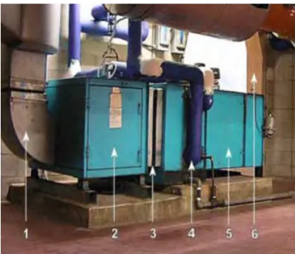
[image:19.612.233.442.255.435.2]According to (Dusan Licina, Chandra Sekhar, (2012) This higher energy use is due to many factors including provision of large amounts of 100% outside air, continuous operation, requirement for stringent internal parameters, high fan energy, etc. At the same time, imbalance seems to exist between the current cost of water and the actual value of that water to the society and environment. Even purified and distributed over long distances, water is available for such a low cost that it usually consumed irrationally.
Figure 2.1: Air Handling Unit
2.1.1 Blower/Fan
6
2.1.1.1 Axial Flow Fan
[image:20.612.229.412.252.388.2]Tangential direction with swirling air created by the rotation of the impeller blades is the axial flow fan. Figure 2.2 shows the movement of axial fan air flow. Kinetic energy to static pressure ( SP ) is a very small increase and potential energy , while the flow velocity is increased by a yielding rotation velocity pressure ( VP ) . In commercial applications, axial fans are commonly found as it moves large volumes of low pressure air. Twin City Fan Companies, Ltd (2000).
Figure 2.2: Air Flow Movement for Axial Fan (Twin City Fan Companies, Ltd 2000)
Propeller fans, tube axial fan, and Vane Axial Fan are three main types of axial flow fan in the industry. The tube axial fan, fan efficiency up to 65% and the fan inside a cylindrical housing. Beside that for propeller fan speed is rotate slowly and moderate temperature, it change the large airflow to small static pressure and efficiency is low approximately 50% or less.
7 Figure 2.3: Type of Axial Fan (Bureau Energy Efficiency Companies (2002).
The table 2.1 show the characteristic and application of the type of Axial Flow Fan. Bureau Energy Efficiency Fan Companies (2002).
Table 2.1: Characteristic of Axial Flow Fan (Bureau Energy Efficiency Fan Companies, 2002)
Type Characteristic
Propeller Fan i. Maximum efficiency at lower pressure
ii. It develop for low pressure and high rate air flow iii. Comparatively noisy
iv. Inexpensive Tube Axial
Fan
i. Fan efficiency up to 65%
ii. Used belt drives to rotate the fan iii. Generates moderate airflow noise
iv. High pressure and efficiencies than propeller fan Vane Axial
Fan
i. The efficiency up to 85% are achievable ii. The airflow profile is uniform
[image:21.612.130.540.448.700.2]8 with small clearance
iv. The vane axial essentially a tube axial fan to straighten airflow with outlet vanes
2.1.1.2 Centrifugal Fan
[image:22.612.219.418.378.518.2]Centrifugal fan is a some device for moving air or gases. The function of centrifugal fan is to rotting impeller to move the air first radially outward toward by centrifugal action. The air thru blade, after that when the blade is rotate the air flow it gain kinetic energy and then the kinetic energy convert to static pressure and increase the pressure of the air which in turn moves the against the resistance caused by duct, damper and other. Figure 2.4 shown the air flow movement of centrifugal fan.
Figure 2.4: Air Flow Movement of Centrifugal Fan (Twin City Fan Companies, Ltd 2000)
9
Figure 2.5: Type of Centrifugal Fan (Bureau Energy Efficiency Fan Companies (2002)
[image:23.612.215.428.423.562.2]The radial blade is industrial workhorses because the static pressure is high, the special about this fan is it can handle heavily contaminated airstream. On top of that the design of radial fan is very simple and it suitable for high temperature and have medium blade speeds. That is not has the blade curve. Figure 2.6 show the blade of radial blade.
Figure 2.6: Radial Blade Fan
10
Figure 2.7: Forward-curve blade fan
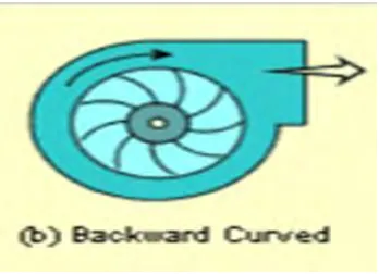
Besides that, for the Backward-curve fan is the orientation of the blade angle is low of impingement with the airstream. The blade and rotational of the blade is different side. Figure 2.8 show the Backward-Inclined fan.
Figure 2.8: Backward-Inclined fan
2.1.2 Heating or Cooling Coil
[image:24.612.235.409.337.463.2]