I
MASSEY UNIVERSITYI
LIBRARYAn Object-Oriented Database· Methodology
for application development with
extended relational or object-oriented DBMS
A thesis presented in partial fulfilment of the requirements
for the degree of
Master of Science in Computer Science at Massey University
Benny
Liew
Firstly, I would like to thank Mr Roger Tagg, my thesis supervisor, for helping me to draft out the contents and using the two case study examples from his 57.0DB(Object-Oriented Database) paper. His advice and guidance throughout is greatly appreciated. Many books and articles were borrowed from him for use in this thesis.
Next, I would like to express my appreciation to Dr. Daniela Mehandjiska-Stavreva, my alternate supervisor for her helpful comments on the structure, written style and presentation of this thesis ..
I would like to thank Massey University Library for using the facilities for my literature search, especially the Library Interloan staff for their excellent services. A total of eight books and more than a dozen of journal articles were requested within New Zealand and overseas. Some of these articles came as far as Canadian universities' libraries.
Thanks go to Mr. Colin Eagle and Mr. Richard Rayner for their excellent support of Postgres on our Sun Microstations network; and also to Mr Todd Cochrane, our PhD student of Computer Science Department, for his past assistance. I wish Todd every success for his PhD research work.
Lastly, I would like to thank Mum and Dad for so many years of upbringing.
Benny Liew, DipSc(CompSc), TechDip(Elect Engg), MSIET
Master of Science(Computer Science) candidate, Massey University,
Dept. of Computer Science, Palmerston North,
ii
Abstract
Recently development methodologies have been proposed which describe themselves as "Object Oriented". While all of them offer approaches to extended data and behavioural modelling, none of them seem fully adequate to address the total concept of object-oriented development They often do not provide constructs which lead to the use of databases, nor do they always recognise the shift from sequential to prototyping style which is inherent in much object-oriented technology.
The objective of this thesis is to lay a framework for an object-oriented methodology suitable for OODBMS. Details of conventional methods for developing database applications, and of the recent 00 methods, have been examined and compared in order to propose a coherent set of tasks and deliverables. Account has also been taken of designing for re-use, which has been one of the main selling points of the 00 approach.
The proposed methodology attempts to address related side issues, with particular focus on object concurrency, which seems particularly thinly covered in many of the current proposals. Many other side issues are also mentioned, but due to time constraints, they are not given any further discussion. The topic is an extremely multi-disciplinary one, and a very wide range of expertise would be necessary to do justice to all these aspects.
•
Rationale for the Research
Object-oriented technology has gained much popularity recently, but methcxlologies
for its use are still at an immature stage. There are many proposed developments of the
00 paradigm by pioneers in this area. Examples are Booch[4], Coad & Yourdon[7,8], Shlaer & Mellor[55], and Meyer[19]. These methodologies are often fairly general in nature and do not specifically address the needs of the
00 paradigm to some special
areas, such as databases.On the other hand, pioneers in OODBMS like Zdonik and Maier[30],
Stonebraker[56-58], Won Kim[15] and Lochovsky[14] and Rolland & Brunet[52]
concentrate more on the requirements and implementation of a specific kind of OODBMS.
The concepts of Object Repository and reusability of software have also been
subjects of discussion lately. There are many advantages associated with
00
prototyping[20].So far, there has not been an 00 paradigm that covers the whole development cycle
of an OODBMS, although there exists many OODBMS tools. This thesis aims to
propose a total, unified paradigm applicable to OODBMS from feasibility through
analysis and design to implementation stage. It emphases particularly on prototyping and
reusability through the use of class libraries and repositories so as to support modern
practices.
One way of doing this is to review all the currently proposed 00 methodologies to
gain an understanding of each in terms of techniques and diagrams used. Sometimes,
different conventions and terms are used by different authors to represent the same
semantic meaning. It is necessary to understand why such individual approaches are
used.
An 00 methodology should also have stages of development just like conventional software development using the functional approach. In addition, steps for each phase of
development is prescribed.
Extended relational and object-oriented databases are examined, and their common
features extracted. This is necessary for the formulation of an OODBMS methodology of
general applicability.
The topic of object-oriented prototyping as applied to application development in
OODBMS is also discussed. 00 prototyping enables quick development of 00 database
iv
Thesis structure
This thesis is made up of eight chapters.
The first chapter of the thesis takes a look at past methodologies for software
development and the evolution of present ones. It briefly describes the existing
methodologies that are well accepted and practised by current software houses. It then
describes the emerging methcxlologies of the 1990s such as RAD and the IBM
AD/Cycle-Repository. Finally, some of the better-known 00 approaches are briefly introduced and summarised.
Chapter 2 discusses the required features of an OODBMS methodology. These
concepts are taken from various sources and each one is given a brief description. Later,
in Chapter 4, some of them are selected to be applied in the proposed methodology.
Chapter 3 gives a brief description of existing methodologies using the
object-oriented paradigm. It is important to note that not all of them are equally suitable for all types of implementation. For instance, Rolland & Brunet's O* Model is particularly
suitable for OODBMS because it supports a lot of database concepts. A comparison is made on the methodologies covered in the literature search. The similarities, differences, strength and deficiency of each is pointed out in a matrix.
Chapter 4 is the proposal of a new methodology for OODBMS. The new proposal
stresses 4 stages of development and the exploitation of object-oriented prototyping for
object iteration. The techniques and diagrams adopted in each step have been described in
Chapter 3.
Chapter
5
examines the application of the proposed paradigm as applied to extended relational database. Postgres is chosen as the extended relational database used toillustrate a case study example.
Chapter 6 examines the application of the proposed paradigm as applied to
OODBMS. Ontos is used as the object-oriented database to illustrate a case study
Chapter 7 offers some conclusions. It also comments on the application of the proposed methodology to the two different types of DBMS. Further possible work on the enhancement of the new methodology is also suggested.
Five sections are included in the Appendices.
Section A gives a brief description of existing fourth generation languages( 4GL) for OODBMS. Samples of the user interfaces of 02, GemStone, and GOOSE are shown. GOOSE is a graphical interface for an 00 database schema environment created at Georgia Institute of Technology.
Section B discusses concurrency control protocols in OODBMS.
Implementation details of Postgres Case Study example are provided in Appendix C. Implementation details of Ontos Case Study example are provided in Appendix D.
Finally in Appendix E, current research areas relating to both types of DBMS are discussed.
vi
Table of Contents
Chapters
Page
1. Review of Software Development Methodology 1
1.1 Introduction 1
1.2 Mainstream Methodologies 1
1.2.1 STRADIS 1
1.2.2 Information Engineering 1
1.2.3 SSADM 2
1.2.4 JSD 3
1.2.5 MERISE 3
1.2.6 SSA 3
1.2.7 Deficiency of mainstream methodologies 3
1.3 Current Trend 4
1.3.1 Rapid Application Development(RAD) 4
1.3.2 IBM AD/Cycle - Repository 7
1.4 Object-Oriented Methodologies 8
1.4.1 Booch Methodology 9
1.4.2 Rolland & Brunnet O* Model 9 1.4.3 Coad & Yourdon OOA and 00D 9 1.4.4 GE Labs Object Modelling Technique 9
1.4.5 Bertrand Meyer 00 Methodology 9
1.4.6 Ivar Jacobson Object-Oriented Development 10 1.4.7 Henderson-Sellers Object-Oriented Life Cycle 11 1.4.8 Summary of Object-Oriented Methodologies 12
1.5 Conclusions
13
2. Required Features of an OODBMS Methodology 14
2.1 Support for development in stages 14
2.2 Oass Identification 14
2.3 Relationships Identification 14
2.4 Behaviour modelling 14
2.5 User Interface Development 15
2.6 Digramming conventions 16
2.7 Object-Oriented CASE Tools 16
2.8 Object-Oriented Prototyping
17
2.9 Object Repository 17
2.10 Support for Reusability
17
2.11 Support for use of OOPL 19
2.12 Support for use of OODBMS features 19
3. Review of Current Object-Oriented Methodologies 20
3.1 Booch Methodology 20
3.2 The Database Object Model by Rolland & Brunet 23
3.3 Coad & Yourdon's Methodology 25
3.3.1 Object-Oriented Analysis 26
3.3.2 Object-Oriented Design 29
3.4 Object-Modelling Technique(OMf) 30
3.5 Comparison of Methodologies 32
4. A Proposed Object-Oriented Methodology for OODBMS 35
4.1 Feasibility Study 37
4.1.1 Overall application purpose 37
4.1.2 Statement of interactions 38
4.1.3 Performance requirements 38
4.1.4 Failure conditions 38
4.1.5 Cost/Benefit analysis 38
4.2 Object-Oriented Analysis 38
4.2.1 Generating a description of the problem domain 39
4.2.2 Constructing the Analysis Model 39
(a) Identify Classes 39
(b) Identify Relationships 41
(c) Structure the Static Aspect 41
(d) Structure the Dynamic Aspect 44
(e) Structure the Static/Dynamic Interaction 47
4.2.3 Object-Oriented Prototyping 47
4.3 Object-Oriented Design 49
4.3.1 Identification of supporting classes 49 4.3.2 Identification of reusable library classes 50 4.3.3 Tailoring the class structure for reusability 50 4.3.4 Choosing a concurrency control protocol 50
4.3.5 Iteration of classes 50
viii
4.4 hnplementation 52
4.4.1 Mapping to the target language 53
4.4.2 hnplementing the application 53
4.4.3 Querying the database 54
4.5 Maintenance of the application 54
4.6 Summary 54
5. Application of the proposed methodology to Postgres Case Study
55
5.1 Features of Postgres
55
5.2 Feasibility Study
55
5.2.1 Overall application purpose
55
5.2.2 Statement of interaction 56
5.2.3 Performance requirements 56
5.2.4 Failure conditions 56
5.2.5 Cost/Benefit analysis 56
5.3 Object-Oriented Analysis 57
5.3.1 Generating a description of the problem domain 57
5.3.2 Constructing the Analysis Model 57
5.3.3 Object-Oriented Prototyping 59
5.4 Object-Oriented Design 60
5.4.1 Identification of supporting classes 60
5.4.2 Identification of reusable library classes 60 5.4.3 Tailoring the class structure for reusability 60
5.4.4 Choosing a concurrency control protocol 60
5.4.5 Iteration of classes 61
5.4.6 System Design 61
5.5 hnplementation 61
5.5.1 Mapping to the target language 61
5.5.2 hnplementing the application 61
5.5.3 Querying the database 61
5.6 Summary 61
6. Application of the proposed methodology to Ontos Case Study 62
6.1 Features of Ontos 62
6.2 Feasibility Study 62
6.2.1 Overall application purpose 62
6.2.2 Statement of interaction 63
6.2.4 Failure conditions 6.2.5 Cost/Benefit analysis 6.3 Object-Oriented Analysis
6.3.1 Generating a description of the problem domain 6.3.2 Constructing the Analysis Mcxlel
6.3.3 Object-Oriented Prototyping 6.4 Object-Oriented Design
6.4.1 Identification of supporting classes 6.4.2 Identification of reusable library classes 6.4.3 Tailoring the class structure for reusability 6.4.4 Choosing a concurrency control protocol 6.4.5 Iteration of classes
6.4.6 System Design 6.5 hnplementation
6.5.1 Mapping to the target language 6.5.2 hnplementing the application 6.5.3 Querying the database 6.6 Summary
7. Conclusion
7.1 Author's comment on the newly proposed methodology 7.2 Comparison of Development for Postgres and Ontos
Appendices
A. 00 Prototyping Tools
B. Concurrency Control in OODBMS
C. hnplementation details of Postgres Case Study D. hnplementation details of Ontos Case Study E. Future Directions of
OODBMS
X
List of Figures
Page
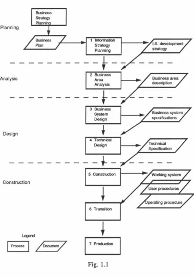
Fig. 1.1 Stage Framework of Information Engineering Methodology 2
Fig. 1.2 The Rapid Iterative Production Prototyping 6
Fig. 1.3 IBM AD/Cycle - Repository 8
Fig. 1.4 Oass/Module Life Cycle 10
Fig. 1.5 Object-Oriented Systems Development 11
Fig. 1.6 Fountain Model 12
Fig. 2.1 Model of Reuse in Object-Oriented Development 18
Fig. 3.1 Booch's Class Diagram 21
Fig. 3.2 Template for the class Alann 21
Fig. 3.3 State Transition Diagram for the class Alarm 22
Fig. 3.4 Booch's Object Diagram 23
Fig. 3.5 Overview of Rolland & Brunet's Object Definition 24
Fig. 3.6 A sample of the O* Model textual description 25
Fig. 3.7 Using a class as a generalisation 27
Fig. 3.8 Using a class object as a generalisation 27
Fig. 3.9 Person Gen-Spec structure, as a lattice 28
Fig. 3.10 "Part-of' structure of Aircraft & Engine 29
Fig. 3.11 "Part-of' structure of Organisation & Clerk 29
Fig. 3.12 Four components and five layers 30
Fig. 3.13 Matrix for the comparison of the methodologies 34
Fig. 4.1 Development stages of the new methodologies 36
Fig. 4.2 Effort as a function of time 39
Fig. 4.3 Association Object 40
Fig. 4.4 Extended E-R diagram 42
Fig. 4.5 Oass Descriptor for the class Reservation 43
Fig. 4.6 Object Communication Diagram 44
Fig. 4.7 State Transition Diagram 45
Fig. 4.8 Event Trace
Diagram
47Fig. 4.9 Mapping Principles for Analysis 48
Fig. 4.10 Mapping Principles for Design 51
Fig. 4.11 Module Diagram 52
Fig. 4.12 Mapping Principles for Implementation 53
Fig. 5.2 Class Descriptor for Postgres Case Study 59
Fig. 6.1 Oass Diagram for Ontos Case Study 66
Fig. 6.2 Oass Descriptor for Lakes 66
Fig. 6.3 State Transition Diagram for class Measuring_point 67 Fig. 6.4 Object Communication Diagram for Ontos Case Study 67
Chapter 1 : Review of Software Development Methodologies Page 1
Chapter 1 : Review of Software Development Methodologies
I, I Introduction
Early 1960s' information systems were not built according to any formal methodology[l,25,26). Analysis work was limited and the emphasis was towards programming. Implementation of information systems was mainly restricted to programming and was based on fixed file structures.
In the late 1960s and 1970s, software development was based largely on function-oriented design, whereby the design is decomposed into a set of interacting units, each having a clearly defined function. Large software systems have been built using this technique and thus it has stood the test of practice. However, the need to develop and maintain large complex software systems using advanced techniques such as databases in a competitive and dynamic environment drove interest in better approaches to software design and development. In the 1980s, this led to a batch of formal "methodologies", which have incorporated some blend of function-oriented and data-oriented approaches.
1.2 Mainstream Methodoloeies Description
Some of the well-known methodologies that have gained widespread acceptance for information systems development today are introduced below:
1.2.1 STRADIS : Structured Analysis, Design and Implementation of Information Systems
This is based on the work of Gane & Sarson. The development of this structured systems approach to analysis came as a result of the earlier development of a structured approach to design. The structured design concepts were first proposed in 197 4 by Stevens, Myers and Constantine (1974) and were later developed and refined by Yourdon and Constantine (1978), and Myers(1975, 1978). Data flow diagrams are constructed to represent the existing system and its interfaces.
1.2.2 Information Engineering
Planning
Analysis
Design
Construction
Stage Framework of Information Engineering Methodology
Business Strategy Plannin
1 Information Strategy Planning
-}-1 · ""''""' Area
Analysis
-
-
}
-I
3 Business System
Design
Business area desaiption
4 Technical
Design
I ..,.
/Technical / / Specification ._ t_,c_
-I·
eoo,~.
I
+
6 Transition
1,---1
Fig. 1.1
1.2,3
Structured Systems Analysis and Desi~ Methodolo~<SSADM}
SSADM[21] is a data-driven methodology developed originally by U.K.
consultants, Learmonth and Burchett Management Systems and the U .K.Central
[image:15.568.125.505.115.657.2]Chapter 1 : Review of Software Development Methodologies Page 3
in which the first three phases are classified into systems analysis and the last three are systems design. They are :
(a) analysis of the current system,
(b) specification of the required system,
(c) user selection of Service Levels, including technical options,
(d) detailed data design,
(e) detailed procedure design,
(f) physical design control.
Data flow diagrams and entity models are needed to represent the static views of the
system and a function/event matrix and an entity/event matrix are used to show the effects
of time on the system.
1.2.4 Jackson Structured Design{JSD)
JSD[l 1] emphasises on the developing of maintainable software systems, and less
on organisational need. Topics such as project selection, cost justification, requirements
analysis, project management, user interface, procedure design or user participation are
not addressed. JSD does not deal in detail with database design or file design. The
major phases of JSD are :
(a) entity step action,
(b) entity structure step,
(c) initial model step,
(d) function step,
(e) system timing step,
(f) implementation step.
1.2.5 MERISE
MERISE[21] supports four stages of information system development. It
combines an entity-relationship approach for data and a Petri-net based approach for
processes.
1.2.6 Structured Systems Analysis(SSA)
SSA[21] was developed by Exxon in 1978, combining functional decomposition,
data flow, relational data modelling and Jackson Structured Programming(JSP)
1
.
2. 7 Deficiency
ofmainstream methodolo~es
The 1980s have witnessed a growth in the number and variety of information systems methodologies. This increase in number of methodologies has caused much
confusion. Many are the same(or very similar) and yet they have different 'brand
names'. Some of them emphase in the techniques, the role of the computer, the
documentation or the role of the people using the system. Some methodologies
emphasize the importance of data and the development of a database. Some concentrate
on analysis, others on design or implementation.
The classical waterfall software development life cycle, which is extensively used,
is sometimes treated as a process in which work proceeds from one phase to another. It
would be more difficult to return to the previous phase when the specification changes in comparison with 00 development. Reasons why the traditional life cycle is inadequate
for software development are :
(a) It assumes a relatively uniform progression of discrete steps, which includes
little or no iteration,
(b) Due to the low cohesion and high coupling nature of program modules, it is
difficult for the software to accomodate change which is a very desirable
factor because each system is built from scratch and maintenance costs
account for a large share of development cost,
(c) It does not accomodate the sort of evolutionary development made possible
by rapid prototyping tools and 4GL,
(d) It does not allow future modes of software development like automatic code
generation, module code transformation and 'knowledge-based' software
development assistance,
(e) There is no emphasis on re-use of the software developed.
I.
3 Current trends
In the early 1990's, there have been two new developments in the marketplace.
One is Rapid Applications Development(RAD); the other is the IBM AD/Cycle
applications development framework.
1. 3.1 Rapid Application Development<RAD}
RAD[18] may be defined as the process of building and refining a working model
or prototype of the final software system during the development process. The main
purpose of prototyping is to refine functions, inputs and outputs during the design phase
Chapter 1 : Review of Software Development Methodologies Page 5
substitute for good analysis and design, but rather it is another way of producing results.
If used properly, prototyping can be an effective tool and an aid in developing systems
that allow closer user participation in the process, leading to information systems that
meet the needs of the business.
Prototyping has been an informal methodology for quite some time. However,
over the years, more experiences are gained in this area, and now it is possible to come
up with some form of requirements or standards. The reason for prototyping is that the
formal lifecycle is actually delaying the delivery of the final product It is becoming the
major cause of the application backlog. Moreover, the elapsed time between
requirements and a delivered product erodes a customer's confidence. Perhaps, people
are more impatient and pragmatic these days and would like to see some form of results
earlier on. Gladden[18] suggests delivering any form of a prototype as quickly as
possible. This approach is typified by Gilb[9] and Martin[l 7, 18].
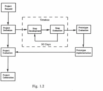
An approach to making prototyping successful was developed by Du Pont in 1985,
called RIPP[3]. The approach was developed around the use of a CASE tool - CorVision
from Cortex. A proposal and definition report was drafted between 10 to 15 days before
proceeding to prototyping. The timebox is basically an iteration development process of
the prototype limited to a maximum of 90 days before being evaluated again. DuPont's
first project using RIPP was completed in
5
man months compared with the 28 to 36months using traditional approaches. This approach has saved them $2.3 million over 3
years, in 15 systems at 9 sites.
The RAD lifecycle has 4 phases[3] as applied in RIPP :
(a) Requirements Planning
(b) User Design,
(c) Rapid Construction,
(d) Transition.
During the first phase, developers create an outline model of the chosen area and
define the scope of the planned system. Business executives, users, and developers take
part in workshops(called the Joint Requirements Planning Workshop - JRP) that
progress through a structured set of steps. All the results of the workshops are recorded
using an integrated CASE(I-CASE) tool. The I-CASE tool is a repository for
The Rapid Iterative Production Prototyping Project Request
,
Project Definition ' Project Evaluation,
~
~
r
-I
I -
-
-I
I
L
-Timebox
Step Step
-
Evaluation...
t
I
90 Days
-Fig. 1.2
7
I
I
--
Prototype EvaluationI
I
_J
,
Prototype Implementation
The User Design stage requires that end-users part1c1pate strongly in the
nontechnical design of the system under the guidance of an IS developer. User Design is
done in a Joint Applications Design(JAD) workshop, which completes the detailed
analysis of business activities and develops the outline design of the system. The
information recorded in the I-CASE tool is used as input and is further refined. This
stage usually lasts three to five weeks.
The third stage involves the design and implementation of the proposed system,
which was outline in the previous stage. The software is constructed using an iterative
technique. Finally this stage includes activities needed to prepare for cut over to
production status. The I-CASE tool is used to generate the application code from
database definitions.
When the system is cut over in the last stage, a variety of actions is needed,
including comprehensive testing, end-user training, organisationanal changes and
operation in parallel with the previous system until the new system settles in.
Prototyping approaches have the following advantages:
(a) improved developer user communications
(b) increased developer productivity (c) working model versus a paper model
[image:19.567.149.489.79.379.2]Chapter 1 : Review of Software Development Methodologies
(e) user specification is changeable at any st.age
(f) reduction in user training due to early participation
(g) production of error-free applications
However, the disadvantages are :
Page 7
(a) configuration management and version control of prototypes is more difficult
than with conventional development. Prototyping can result in many trial
systems. It is possible to get versions mixed or to be unable to recover an
earlier prototype version. Configuration management software can reduce
this problem
(b) keeping documentation up to date may be difficult because of its rapidly
changing and iterative nature
(c) maintaining discipline and objectives in the development team is difficult
because it is possible to become distracted from the legitimate goals of the
prototype due to the fluid nature and constant demands of prototyping
(d) Planning and allocating resource is difficult in an environment dealing with
uncertainty and unknown
(e) ultimate testing may be neglected and left to the users.
Incidentially, a RAD approach has also been integrated into Information
Engineering by Texas Instruments (James Martin Associates).
1.3.2 IBM AD/Cycle-Repository
In Sep 1989, IBM became a standard bearer for the computer-aided software
engineering(CASE) industry by laying out its plan for the software development process.
AD/Cycle-Repository[38,53,54] is an integrated framework intended for a CASE
environment, and compatible with a range of development tools and techniques from
many vendors. The goal is to vastly improve productivity in the applications
development process. The only way to achieve this is to automate code generation
through the use of models rather than conventional programming. Also it standardises
repository storage of development objects. All CASE tools from other vendors, in order
to link to AD/Cycle, must comply with certain IBM standards. However, no attempt has
been made to create a standard in the methodologies themselves.
The primary benefit of the open repository-based environment is that users should
be able to plug tools developed by CASE vendors complying with the repository standard
into the environment and then use them together. CASE tools supporting various
methodologies use the services of the Repository Manager to store user-defined
format within the Repository Manager, from which it will be ultimately used to drive a code generator.
However, until now, it has not become popular due to a number of reasons. The MVS Repository Manager is not a stable product Only a few CASE tools are compatible and it is difficult for other vendors to plug their CASE tools into the Repository. There is also problem with LAN configuration which is a important desired feature because today's CASE tool is geographically dispersed. Vendors with CASE tools running under MS-DOS and Unix have to rewrite them for OS/2EE for IBM PC and SAA compliance. One problem is that until now OS/2EE has not been popular.
While IBM is promoting integrated CASE in a mainframe environment, Digital Equipment Corp is following a more distributed path[53]. DECs integrated CASE standard is known
as
A TIS(A Tool Integration Standard) and COD/Repository in the VAX/VMS and Ultrix enviroments.LAN
IBM AD/Cycle-Repository
u
Protocol
1 Pe« ID peer protocol 2 Life Cycle Transition Protocol
(Movem«1t ID Final Cocle)
Enterprise
Repository
3 Reposltorylllbraty Exchange Protocol
~
_c'°_A~_H_T''!_.
G 1~1 G
~lienV
~
ardGUI
L_)
Local Reposik>ry Local
Repository
Local Repository
Fig. 1.3
1,4 Obiect-Oriented MethodoJ02ies
[image:21.567.111.484.323.664.2]Object-Chapter 1 : Review of Software Development Methodologies Page 9
oriented methodology is defined as an application development strategy that models both requirements and software solutions as collections of objects that contain both data
structure and behaviour.
However, many software organisations have developed standards and methods
based on the functional approach and are understandably reluctant to embark on some
design techniques that are still immature and unproven. Hence, any migration to new
methods is likely to be a gradual one.
Current application of the 00 paradigm has been limited to Design and
Implementation due to the widespread use of C++ and Smalltalk in a small scale
environment. Less has been done on the Analysis, although this is crucial for the
construction of large and complex 00 Information Systems.
The Object-Oriented development cycle is covered, in particular, by Booch[4],
Budd[5], Henderson-Sellers[l0,40], Korson[43], Jacobson[l2,41], Bailin[31] and
Coad & Yourdon[7,8].
1.4.1 Booch Methodology
Early versions of the methodology, proposed by Grady Booch were centered
around Ada. In his most recent book, Booch introduces four models to capture 00
semantics, which are then mappable to several target 00 software environments.
1.4.2 Rolland
&
Brunet0*
ModelThis metholodogy[52], by the two authors at the University of Paris, concentrates
on development for OODBMS, particularly the 02 system.
1.4.3 Coad & Yourdon OOA andOOD
This methodology[? ,8] has been widely published through two books, one each on
Analysis and Design, and a CASE tool has been developed.
1.4.4 GE Labs Object Modellin& Technique(QMT)
This technique[24] is developed by Rumbaugh, Blaha, Premerlani, Eddy and
Lorensen at General Electric R&D Center, Schenectady, New York. Originally, this
technique[34] was meant for use with relational database but has been modified to suit the
object-oriented one.
1.4.5 Bertrand MeyerOO Methodology
Meyer's object-oriented methodology is centered around his OOPL, Eiffel. Not
much is discussed about OOA. However, he claims that Eiffel language can both handle
the same : objects. Objects and relationships between objects are identified in both the
analysis and design phases. The cluster model has been proposed by Meyer as a life cycle for a tightly related group of classes, or cluster, in which three phases are
identified.
aass/Module Life Cycle
Ouster n
( SPEC HDESIMP )--->(VALGEN)
( SPEC )---,>{oESIMP )1-~>(VALGE0
Ouster 2
c
SPEC )----,>(DESIMPH
VALGE0Ouster 1
Ouster model proposed by Meyer.
SPEC• specification; DESIMP .. design+implementation; VALGEN=validation+ generalisation
Fig. 1.4
First, a specification is written by the systems designer(SPEC), then this is
designed and implemented(DESIMP)(one process in a language like Eiffel) and finally it
is validated and generalised(V ALGEN). This life cycle occurs for different clusters of
classes at different times. For example, a window cluster and a graphics cluster of classes could be specified, designed and implemented and then validated and generalised
at different times. These phases are also iterative with refinements added
1.4.6 Ivar Jacobson Object-Oriented Development
Ivar Jacobson come out with an early version of 00 systems development in 1987.
This technique originates from his work at Ericsson Telecom and since then has been
used extensively within the whole Swedish telecommunication industry.
Basically, this paradigm describes a system as a set of properly interconnected
blocks - each building block representing a packaged service of the system. A block may
itself be made up of other, low-level blocks or by components. Components are standard
modules which can be used for many different applications. The lowest-level blocks are
made up of components only. Blocks as well as components are naturally implemented
as classes using object-oriented programming. The designers are consequently provided
with a set of components when building applications by means of blocks.
There is one interesting assumption made in this paradigm with regards to object
concurrency. It is assumed that there is an infinite processor capacity, the execution
Chapter 1 : Review of Software Development Methodologies Page 11
disregarded and the course of events may be serialised. This assumption may not be adequate for the general case.
lysteffl
Fig 1.5
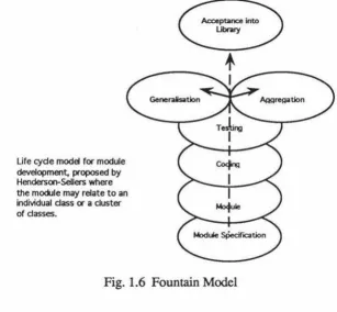
1.4.7 Henderson-Sellers 00 Life Cycle
This methodology is developed at the University of New South Wales, Australia which describes the life cycle of 00 systems devleopment. It focuses more on the front-end and high-level analysis. There
are
seven proposed steps to follow and earlier efforts made by Coad & Yourdon, Shlaer & Mellor, Bailin, and Wirfs-Brock are applied in these stages:(a) Undertake object-oriented system requirements specification,
(b) Identify the objects and the services each can provide(interface),
(c) Establish interactions between objects in terms of services required and services rendered,
(d) Analyse stage merges into design stage : use of lower-level entity data flow diagrams/Information flow diagrams,
(e) Consider the bottom-up concerns and use of library classes, (f) Introduce hierarchical inheritance relationships as required, (g) Aggregate and/or generalise of classes.
Life cyde model for module development, proposed by Henderson-Sellers where the mod.lie may relate to an individual dass or a duster of dasses.
Fig. 1.6 Fountain Model
1.4,8
Summazy of 00 Methodolo~es
Booch and Henderson-Sellers have agreed that object-oriented design embodies an
incremental, iterative process in between successive stages. Both Jacobson and Henderson-Sellers' ideas are particularly suitable for developing very large
object-oriented software systems( > 10 man-years). Another interesting point to note is that
boundaries of analysis, design and implementation stages in object-oriented software development are blurred. Examples are Coad & Yourdon, who overlap between
object-oriented analysis and design. Booch combines design with implementation.
Henderson-Sellers has identified the iterative process and comes out with the
fountain model to replace the classical waterfall model. Development reaches a high level
only to fall back to a previous level if so needed, to begin the climb once again. This is a
better model of reality then the traditional waterfall model. Firstly, it provides a diagrammatic version of the stages present in an software life cycle and a clearer
representation of the iteration and overlap made possible by object-oriented technology.
Secondly, since the foundation of a successful software development is its requirements
analysis and specifications, this stage has been placed at the base of the diagram. The
fountain model can also be extended to the life cycle of a module, as outlined in Section
[image:25.567.158.465.60.344.2]Chapter 1 : Review of Software Development Methodologies Page 13
are:
Some of the advantages of object-oriented paradigm at the Analysis level[7,43] are:
(a)
It can handle more complicated problem domains; emphasing more on the
understanding of problem domains since it is based on objects, and not
just functions or processes alone,
(b)
It can improve interaction between analyst and client since it organises
analysis and specification using the methods of organisation that pervade
people's thinking,
(c)
It can increase the internal consistency of analysis results. Object-oriented
analysis introduced by several authors have consistent diagramming,
(d)
The results obtained in Analysis can be reused on some similar projects
.
Some of the advantages of object-oriented paradigm at the Design level[8,27 ,43]
(a)
Object-oriented design is actually a continuation of the efforts made at the
Analysis stage,
(b)
Results and experiences gained during the Analysis stage can be reused,
(c)
Object-oriented prototyping is used which increases productivity,
(d)
Low life cycle cost,
(e)
Modularity,
(f)
Maintenability
.
l, 5 Conclusions
Most of the well-known 00 methodologies have been given a brief intrcxluction.
While all of them offer approaches to extended
dataand behavioural modelling, none of
them seem fully adequate to address the issues specifically related to 00 database
Chapter 2 : Required Features of an OODBMS Methodology
This chapter suggests and discusses what ingredients are necessary in an
object-oriented database methodology and how different each component needs to be from the
conventional counterpart. These ideas draw on many sources of existing 00
methodologies and the existing OODBMS methodology[52] covered during the literature
search.
2, 1
Support for development in sta2es
An OODBMS methodology should be developed in stages. In conventional methodologies used with both functional and database approaches, there are discrete
steps that progress from one to another. In 00 development, the phases may be blurred
because the same objects are under study throughout. The only difference between
stages is the enrichment of information as the development progresses towards the
deliverable.
Nevertheless, it seems desirable that any 00 methodology should recognise not
only Analysis, Design and Implementation stages, but also a preliminary Feasibility stage
as included in most conventional methodologies.
2, 2
Class Identification
An OODBMS should have provisions for class identification. The inclusion of a
recommended approach to identifying suitable object classes is an important requirement.
The parallel stages in conventional methodologies are identification of entity types and
functions. The identification process needs to be defined in the form of guidelines as to
groups of object classes which should be looked for in some description of the problem
domain.
2,
3 Relationships Identification
Just as in a conventional database-oriented methodology, the next requirement is to
identify relationships, "is-a", "part-of', and "instance of'. This process would be similar
to the relationships identification in most 00 methodologies. Because of the importance
of inheritance in target 00 software environments, and because of the relationships
support many OODBMS give for complex data types, the "is-a" and "part-of'
relationships assume a greater role than in conventional methodologies. There is often
also a need to identify "instance of' relationships as individual object behaviour may be
Chapter 2 : Required Features of an OODBMS Methodology Page 15
However, consideration of other types of relationships ought not to be discarded as they represent an important part of the semantics of the problem domain.
A modelling structure is then required to cover the identified relationships (the "static" part of the Analysis. The structure includes a range of diagrams and templates for designer-user, designer-designer and designer-CASE tool interaction. Ideally, these facilities should represent an evolutionary development of existing ones rather than totally new concepts.
2, 4 Behaviour rnodelline
Behaviour modelling should be supported in the OODBMS methodology. This is the area which appears to involve the most differences from a conventional approach, since "procedures" are no longer independent elements in the modelling system, and must be encapsulated with objects or object classes.
"CRUD" Create, Read, Update, Delete as used in many current methodologies -represents the easy part of the problem, as these functions can be encapsulated relatively simply to the objects(simple or complex) that they act upon.
The more critical requirement is for approaches to cover the following :
(a) multi-object transactions, where a unit of work can be identified in the problem domain which requires all subtasks to be completed successfully (b) asynchronous triggering and messsage passing, where actions on one object
lead over time to actions on other objects (c) synchronisation of parallel threads of activity.
Modelling concepts in addition to the main class structure are needed, involving such things as intra-object behaviour, inter-object message passing, state transition and event dependency. Again it is desirable that existing concepts should be evolved whenever possible.
2,
s
User Interface Development
In
database-oriented methodologies, the user interface has tended to be peripheral to the main analysis model, and is brought in at the design stage in a fairly separated fashion. With an 00 approach, the user interface can be expressed as a set of objects and classes at a number of levels of abstraction, in both the Analysis and Design.2, 6
Dia2rammim: conventions
A recommended diagramming notation covering all the features suggested for object-oriented systems development should be enforced throughout to model both the static and dynamic aspects of the system, i.e. the analysis and design results.
2,7
Obiect-Orieuted CASE Tools
It is desirable that the methodology is supported by an 00 CASE tool. Existing tools can be classified into front-end and back-end. These are used to construct the model which would at the same time checked for the semantics. At the present moment, very few are widely marketed.
2. 7 .1 Tools for analysis and designffront-end)
One of the desirable characteristics of tools at the front-end is a graphics-based system supporting object-oriented design notation. This will enforce the notational conventions of OOA and 00D, and maintain control over the design products, and co-ordinate activities of a team of developers. It can be used throughout the life cycle as the design evolves into a production implementation. Such a tool is also useful in system maintenance.
2. 7 .2 Tools for implementation{back--end)
Implementation normally requires the use of some language, usually but not necessary an OOPL. A number of languages are accompanied by toolkits which support the low level design and implementation process. Some of the desirable characteristics of tools at the back-end are as follows:
(a) An object browser that knows about the class structure and module architecture of a system. Class hierarchies can become so complex that it is difficult even to find all of the abstractions that are part of the design or are candidates for reuse.
(b) An incremental compiler to handle minor changes rather than to recompile the whole program again which may be very time consuming for a large development
(c) Debuggers that know about class and object semantics and support for multiple threads of control processes. The tool should permit the developer to exert control over the individual threads of control.
(d) Configuration management and versioning tools for large projects.
(e) Class library browser that allow developers to locate classes and modules
Chapter 2 : Required Features of an OODBMS Methodology Page 17
and the library grows as domain-specific reusable software components
are added over time.
2, 8 Obiect-Oriented Prototypine
The technique of 00 prototyping should also be incorporated as part of the OODBMS development methodology because it is an inexpensive and quick way of
demonstrating the likely functionality of a final system[20]. This approach is especially
suitable with 00 paradigm. The prototyping tools therefore must be capable of
generating a demonstratable system before all system classes are fully defined. A number of OODBMS prototyping tools are described in the Appendix A.
2,9
Ob
iect Repository
An OODBMS methodology should support the concept of Object Repository. The
Object Repository[29] should be the foundation of any application development and is
vital for 00 prototyping.
It is a centrally controlled data store which contains all object components built-up
from both current Analysis and Design work, and past projects developed using different
prototyping tools across various platforms. Early in the lifecycle, information already in
the Repository is extracted and put to use. Information developed during planning is
stored in the Repository for later use in Design. Information produced in design is stored
in the Repository for use in the construction of the application. This technique enables
fast development by reusing existing templates, structures, models and designs.
The Repository ensures consistency among diagrams and helps to enforce technical
quality. It enables the integration of prototyping tools, code reuse and the automation of
00 software development process.
As more and more objects are added, a classification utility should be provided to
group similar objects together so that searching is made easier.
Local Repositories are called the Class Libraries and are built into the prototyping
tools used.
2,
t
QSupport for Reusability
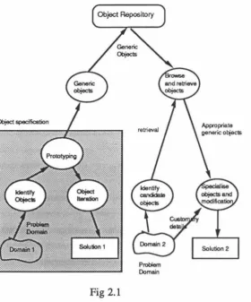
Reusability can only be supported by utilising Class Libraries and Repositories.
The object-oriented paradigm combines design techniques and language features to
provide strong support for reuse of software modules[61]. A schematic view of this
process is shown in Fig 2.1.
This process, quite unlike traditional methodologies, involves reference to objects
(a) Designing objects in one domain with a view to their being reusable by other domains. This typically involves the inclusion of higher-level generic objects, which are not a strict requirement of this domain, but introduce a level of generality which makes re-use possible.
(b) Finding suitable generic objects in the Object Repository which can be specialised for use in the new problem domain.
Model of ReuN In Object-Oriented Development
[image:31.565.164.445.259.597.2]Object Repository
Fig 2.1
Problem
Domain
To enable reuse the new application has to be analysed to establish the differences between the generic objects in the Repository and the new applications, so that the appropriate specialisation can be carried out Furthermore, some parts of the generic objects may be inappropriate for the new application. In this case, attributes and methods of the generic objects would need to be modified to suit the specialisation.
Chapter 2 : Required Features of an OODBMS Methodology Page 19
(a) the use of an Object Repository as a central feature, with classification and
searching facilities (Section 2.9).
(b) the inclusion of sub-tasks, both to search for off-the-shelf objects, and to
create generic objects for later re-use.
2.11
Support for use of OOPL
In order to support OOPL, the methodology must be able to map the concepts it
deals with at the Analysis and Design stages into concepts used by the implementation
language which is normally an
OOPL.
Although iteration, exception handling and pararneterised classes have not yet been
implemented in some OOPL languages, an 00 methodology should support such
features that might be implemented in later versions of the languages.
2.12
Support for use of OODBMS features
OODBMS, extended relational DBMS and other target environments are not
uniform in the concepts they directly support. Examples are :
(a) limited levels of encapsulation,
(b) explicit rule and trigger systems,
(c) explicit versioning.
These non-standard features occur primarily in the extended relational databases
like Postgres[56,57,58] and Starburst[46].
There are good arguments for including explicit rules and version relationships in
the 00 Analysis and Design model. However, if targeting an OODBMS, these concepts
have to be "mapped out" into methods or supporting classes.
Likewise, encapsulation that cannot be supported in a target DBMS needs to be
"mapped out" into an embedding software structure that could be regarded as belonging
Chapter 3 : Introduction to Object-Oriented Methodologies
No single approach to Object-Oriented Methodology has yet reached widespread
acceptance[ 40]. A number of approaches can be considered as possible "leading
contenders", and this chapter provides a brief introduction to some of these:
(a) Grady Booch[ 4]
(b) The O* Model by Collete Rolland and Joel Brunet[52]
(c) Coad and Yourdon[7,8]
(d) GE Labs OMT[24]
Other proposals, not discussed in detail here, include Meyer[19], Shlaer & Mellor[55], Jacobson[12,41], Wybolt[63], and Hayes & Coleman[39]. Also the
Object-Oriented System Development methodology proposed by Henderson-Sellers[l0,40] has
already been mentioned in Chapter I. Some of the above still favour having a functional
design as part of their object-oriented methodology[55,63,39,24]. A comparison of (a)
through (d) will be provided later in the chapter.
3. I Booch Methodoloi:r
Booch[4] defines a class as a set of objects that share a common structure and a
common behaviour while an object is an instance of a class. A method is an operation upon an object, defined as part of the declaration of a class.
Booch does not say a great deal about object-oriented analysis, but concentrates
more on design and implementation issues. Booch introduces four diagrams which form
the basic notation of object-oriented design out of which the first two are most frequently
used and important They are the (i) class diagram, (ii) object diagram, (iii) module
diagram, (iv) process diagram. The first two forms the logical view of a system while
the last two are used to describe the physical structure of the system and the software and hardware implementation. The static and dynamic semantics for the class and object
diagram are also represented.
In the class diagram, Booch uses chained cloud icons to represent abstractions of a real-world class entities. There are also interface and implementation classes,
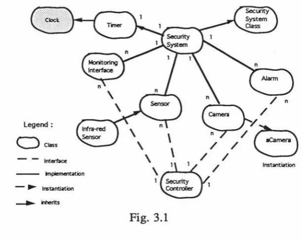
characteristic of OOPL concepts. Metaclass relationship is another type of relationship which is used to represent a class of a class relationship. In the below example, timer belongs to the metaclass of clocks. The clock metaclass is shown in shaded cloud.
Chapter 3 : Introduction to Object-Oriented Methodologies Page 21
required in real-time applications. Others include utility class which represents a single free subprogram or a collection of such free subprograms.
The two important relationships, aggregationpart-of') and generalisation ("is-a") are supported. Generalisation is represented by inheritance while aggregation is represented in the attributes of classes.
For a simple example, fig
3.1
shows a security system which uses the class monitoring interface for the interface part and classes sensor, camera, and alann for implementation. Infra-red sensor is a subclass of class sensor which inherits attributes and behaviour from the class Sensor and ACamera is an instantiation of the class Camera. Cardinality of relationships is also shown.Legend:
C::>
Class- - lnterboe
- ... Instantiation
/ n
q/
\
I
~
/
( .,...,)
\
\
/ /\©1 /
1 Security Controller lInstantiation
Fig.
3.1
Here, security controller is viewed as a transaction object for the purpose of separating direct visibility between classes and also to coordinate activities.
Notice that the attributes and operations
are
not demonstrated in the cloud icons. Details are left to be defined in the class template to avoid untidiness. Below is an example of templates used to define the classes.Name:
Cardinality :
Hierarchy:
Superclass :
Public Interface :
Uses: Operations :
Implementation :
Uses: Attributes :Alarm
n
Object
Security Controller respondtoAlarmFault
activateAlann resetAlarm
[image:34.564.151.456.248.491.2]Operations :
Concurrency :
alann_location active
Fig 3.2 Template for the class Alann
A good approach is to review the list of key abstractions and select only those that represent the largest conceptual chunks, that is elements at the highest level of abstractions. Each of the cloud icon may be further decomposed to review more details of the system structure if necessary. This is analogous to functional decomposition in data flow diagrams.
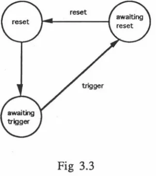
State transition diagrams are used adjunct to the class diagram to model the dynamic aspect of the system.
State Transition Diagram for the Class Alarm
Fig 3.3
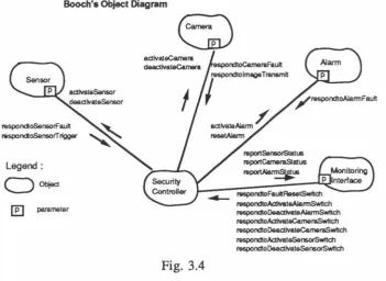
The object diagram is used to show existence of objects and their relationships in the logical design of a system, representing a time-lapse snapshot in time of an otherwise transitory event Object visibility and synchronisation are also indicated inthe object diagram. Object visibility is about how two objects communicate with one another in their interface fields, lexical scope and passing parameters. Messages sent may be
[image:35.565.235.396.321.502.2]Chapter 3 Introduction to Object-Oriented Methodologies Page 23
Booch also uses timing diagrams to show the duration and sequence of the
operations of objects against time. It would not be elaborated here.
Booch's Object Diagram
respondloSensorf" ault respondloSensorTrlgger
Legend:
C)
Objed[El parameter
Fig. 3.4
repo,tSensorSlatl.15 repo,tCameraSla!us
r e ~ U &
respondloFaullAllsetSwttd1 respondtoActlYateAlarmSwltch respondtoOeadlYateAlarmSwttch respondtoAalvateCameraSwttch respondtoOeadlvateCameraSwftch raspondtoAdlvateSen&OrSwttch respondto0eadlYateSe"60fSwttd1
A module diagram is used to show the allocation of classes and objects to modules in the physical design of a system. Some object-based and object-oriented programming
languages support the concept of a module as separate from a class or object. This
construct may be as simple as separately compiled files in C++ or as sophisticated as the idea of packages in Ada. It is the responsibility of the designer to decide how to allocate
classes, objects, and other declarations to physical modules. Languages that do not support modules clearly do not require this notation. 1be two most important elements of a module architecture are modules and module visibility.
The process diagram is used to visualise and then reason about the problem of
allocating processes to processors in the physical design of a system. The three most
important element of process architecture are processors, devices and connections. A
processor is a piece of hardware capable of executing programs; a device has no such
computing power. Processors and devices communicate with one another. Details of
each kind of element are again described in templates. The process diagram is more about showing hardware configuration of a system.
3,2 Ibe Database Obiect Model by Rolland
&
Brunet
Collette Rolland and Joel Brunet's methodology for object database design is
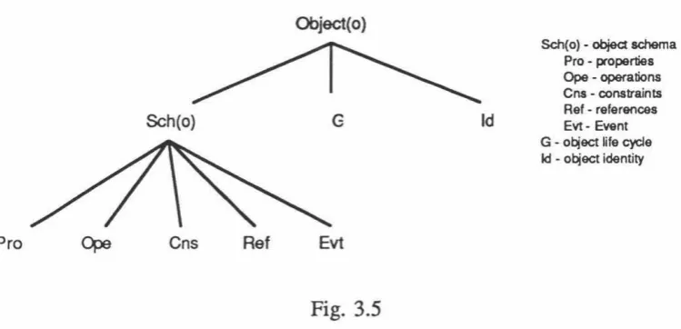
presented in the Object model. In their definition, an object is fully described by an
[image:36.564.108.460.127.383.2]Over,lew of RollMd • Brunet'• Object o.ftnltlon Object(o)
Sch(o) G
Pro
Fig. 3.5
Id
Sch(o) -object schema Pro • propertiea Ope · operations
Cns. constraints Rel • relerencea Evt • Event G • o~ect ~le cycle Id • o~ect identity
The object scheme of an object is further described by its properties, a set of possible operations on the object, constraints to be verified by the object, static links consisting of a set of references of the object with other objects, a set of events which may be stimulated by particular state changes of the object. The first three items,
Properties, Operations,
andConstraints,
characterise the local static aspect of theobject while
Reference
andEvent
specify the dynamic aspect of the object Properties, operations, constraints, reference are shown using in astatic interrelations diagram.
This is not very sophisticated as compared to OMT or Coad & Y ourdon' s class model for analysis and hence it would not be illustrated here. The last item is shown using their notation of a dynamic interrelations diagram.
It
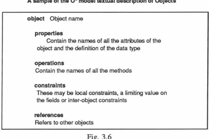
shows to a certain extent of object visibility but is not very helpful on message passing compared with Booch's object diagram. An example of a dynamic interrelations diagram is shown in Appendix B.A complete description of the object scheme is done on the template. An example of a class descriptor for a generic object is shown in Fig 3.6. The state of the object is the concatenation of all its properties and reference values at a given time. State changes of an object are triggered by an internal or external event. This behaviour may be represented by state transition diagrams and concurrency by Petri-nets although they are not explicitly shown.
Every object is given an identifier. This is similar to the concept of a surrogate key .
for a relation in extended relational databases.
[image:37.564.95.470.90.271.2]Chapter 3 Introduction to Object-Oriented Methodologies
A sample of the O* model textual description of Objects
object Object name
properties
Contain the names of all the attributes of the object and the definition of the data type
operations
Contain the names of all the methods
constraints
These may be local constraints, a limiting value on the fields or inter-object constraints
references
Refers to other objects
Fig. 3.6
Page 25
Rolland
&
Brunet's methodology is more suitable for object database design particularly because it proposes a textual description of objects which containstriggers(rules in Postgres) and operations(functions in Postgres). The concept of references is also used, which is typical of OODBMS.
3, 3 Coad
&
Yourdon 's Methodoloi:y
Coad & Yourdon's 00 Methcxlology is divided into Analysis and Design. They
have introduced five steps in real-world abstraction. They are :
(a) Classes
(b) Structures
(c) Subjects
(d) Attributes (e) Services
Some guidelines are used for identifying classes. The potential classes in a problem
domain are structures, other systems, devices, things or events remembered, roles
played, operational procedures, sites and organisational units. The first four are more
important
"Structures" are commonly used
in
data modelling. They are formed by the "is-a" [image:38.564.132.470.107.331.2]"Other systems and devices" include a related system or single entity that the system under present consideration interacts with. Examples are the user-interface system or a sensor that forms part of a data logging system.
"Things or events remembered" over time are recorded in storage objects. These storage objects may also be called data objects, and are usually persistent
"Roles played" by objects are termed as temporal objects which exist as a result of relationships.
In their book, Object-Oriented Analysis, the above five steps are applied in the problem domain component Besides the problem domain component, which is known as the schema in database terms, there are also other components that need to be examined which make up an object-oriented systems. The other three components human interaction, task management and data management are further discussed in their book, Object-Oriented Design. The book also demonstrates the implementation of all the four components using OOPL.
3.3.1 Object-Oriented Analysis
Much work on OOA has been carried out by Coad and Y ourdon. In fact, the authors acknowledge that OOA is a relatively new method of managing real-world complexity, and that their recommendations should be tailored whenever to suit the organisation or project needs.
It is essential to identify objects and their classes within the problem domain. Some useful hints of finding objects occur in the client's summary like singular or adjective noun, things that have a structure, things that interact with other systems, devices itself, human or things that played a role, systems that require remembrance of particular operations or excercise sequencing, physical location or sites, and organisation units. Recognition of objects will become familiar with practice and a fair understanding of the environment under consideration. Besides these, one would also need to consider the behaviour, attributes, services offered by the identified objects. An object class contains instances whereas an abstract class does not.
Three important concepts of identification of structures are Generalisation, Specialisation and Whole-Part Structures. The directional notation for demonstrating Generalisation-Specialisation is shown in the below example. The superclass is drawn with a line outward from a semicircle midpoint to point to the subclass.
Consider a certain class of motor as an example. Assuming that there are two types of motors, the standard motors(class A and B) and the submersible ones(Class E). For the submersible ones, the operations are more critical and the standards more stringent.
The superclass is assumed
toprovide only the common attributes without having
Chapter 3 Introduction to Object-Oriented Methodologies Page 27
behaviour of the standard motor, will have other critical attributes of its own, shown in Fig 3.7. This illustration may further be redrawn to Fig. 3.8.
Motor
Model kVA rating v'*-Rlfing P.-r Factor
p , -On P.-=Olf
Jag
rl
I
I
§
,
Sobnerst>le
Tolerance Deplh
"'~·Ion
Fig 3.7 Using a Class as a generalisation
r
'
'
Motor
Model kVA rating
Voltage
Rating
Power Fador Power_On Power_Off Joo
""
~
I
'I r
&bmersble
"'
Toleranoe Depth of ope<alion
~
"'
[image:40.564.200.369.162.359.2] [image:40.564.210.377.436.686.2]LegaName Address
OwnerPerson r
.,
ClerkPerson
CitizenOf DateOf Birth
Userldentification Password
Photo TrombPrint
...
~( _ _ Owne-rCle-rkP-ers-on _ _ )
Fig 3.9. Person Gen-Spec structure, as a lattice
To consider whether an Object Class needs Generalisation or Specialisation check
whether it is in the problem domain, and if there is inheritance between different object
classes. In practice, the most common form of Gen-Spec structure is a lattice as shown
in fig. 3.9.
Whole-Part Structure is shown with a whole Object at the top, and then a part
Object below, with a line drawn between them. A triangle marking shown in Fig 3.10
and Fig 3.11 distinguishes Objects as forming a Whole-Part Structure. Each end of a
Whole-Part structure line is marked with an amount or range, indicating cardinality, at
any given moment in time.
In
Fig 3.10, an aircraft is an assembly of possibly no engines (a glider) or at mostfour engines(Boeing 747) and an engine is part of possibly no aircraft or at most one
aircraft In Fig 3.11, an organisation is a collection of possibly no clerks or at most
[image:41.564.163.434.55.345.2]