Input Uncertainty Sensitivity Enhanced
Non-Singleton Fuzzy Logic Controllers for
Long-Term Navigation of Quadrotor UAVs
Changhong Fu, Andriy Sarabakha, Erdal Kayacan, Christian Wagner, Robert John and Jonathan M. Garibaldi
Abstract—Input uncertainty, e.g., noise on the on-board cam-era and inertial measurement unit, in vision-based control of unmanned aerial vehicles (UAVs) is an inevitable problem. In order to handle input uncertainties as well as further analyze the interaction between the input and the antecedent fuzzy sets (FSs) of non-singleton fuzzy logic controllers (NSFLCs), an input uncertainty sensitivity enhanced NSFLC has been developed in robot operating system (ROS) using the C++ programming language. Based on recent advances in non-singleton inference, the centroid of the intersection of the input and antecedent FSs (Cen-NSFLC) is utilized to calculate the firing strength of each rule instead of the maximum of the intersection used in traditional NSFLC (Tra-NSFLC). An 8-shaped trajectory, consisting of straight and curved lines, is used for the real-time validation of the proposed controllers for a trajectory following problem. An accurate monocular keyframe-based visual-inertial simultaneous localization and mapping (SLAM) approach is used to estimate the position of the quadrotor UAV in GPS-denied unknown environments. The performance of the Cen-NSFLC is compared with a conventional proportional integral derivative (PID) controller, a singleton FLC (SFLC) and a Tra-NSFLC. All controllers are evaluated for different flight speeds, thus introducing different levels of uncertainty into the control problem. Visual-inertial SLAM-based real time quadrotor UAV flight tests demonstrate that not only does the Cen-NSFLC achieve the best control performance among the four controllers, but it also shows better control performance when compared to their singleton counterparts. Considering the bias in the use of model based controllers, e.g. PID, for the control of UAVs, this paper advocates an alternative method, namely Cen-NSFLCs, in uncertain working environments.
Index Terms—Fuzzy logic controller (FLC), unmanned aerial vehicle (UAV), non-singleton FLC (NSFLC), input uncertainty sensitivity enhanced NSFLC, monocular visual-inertial SLAM.
I. INTRODUCTION
R
ECENTLY, quadrotor unmanned aerial vehicles (UAVs) have been applied for a wide range of indoor and outdoor civilian applications, e.g., traffic surveillance [1], search and rescue [2], image velocimetry [3], orchard monitoring [4], 3DChanghong Fu, Andriy Sarabakha and Erdal Kayacan are with School of Mechanical and Aerospace Engineering, Nanyang Technologi-cal University (NTU), 50 Nanyang Avenue, Singapore 639798. (e-mail: [email protected], [email protected], [email protected]).
Changhong Fu and Andriy Sarabakha are with ST Engineering-NTU Corp Laboratory, 50 Nanyang Avenue, Singapore 639798.
Christian Wagner, Robert John and Jonathan M. Garibaldi are with Lab for Uncertainty in Data and Decision Making (LUCID), School of Com-puter Science, University of Nottingham, Nottingham, United Kingdom. (e-mail: [email protected], [email protected], [email protected])
Christian Wagner is with Institute of Computing and Cyber Systems, Michigan Technological University, Houghton, Michigan, USA.
reconstruction [5], wildlife protection [6], perch and stare [7], forest management [8] and person following [9]. The main advantages of these quadrotor UAVs are their small size, low cost, vertical take-off and landing capability as well as their easy maintenance. However, demand for almost perfect design of flight controllers for such aerial vehicles in particular on the operation boundaries remains a challenging task due to several factors, such as inherent underactuation characteristics, coupled translation-rotation dynamics, gyroscopic moments, nlinear dynamic models, aerodynamic damping and on-board mechanical vibration as well as internal (e.g., lack of modeling and inaccuracy of onboard sensors) or external (e.g., illumination variations and blurred areas on onboard captured images) uncertainties. In the literature, conventional controllers, e.g., proportional-integral-derivative (PID) [10], linear quadratic regulator [11], and sliding-mode control [12], have been utilized for the control of quadrotor UAVs to achieve fully autonomous flights. When a linear approximation of the nonlinear dynamic model of the quadrotor UAV is employed to represent the system, lack of modeling might disrupt control performance. Furthermore, the assumption of having small attitude angles must be satisfied during the quadrotor UAV flights because of the same assumption during the lineariza-tion. However, certain applications, e.g. aggressive maneuvers and fast speed applications, push the working conditions towards the nonlinear region, resulting in more uncertainties in the control of the quadrotor UAV. Therefore, an advanced model-free control approach is required to improve the control performance and maneuverability of the quadrotor UAVs for fast and aggressive maneuvers under uncertain and noisy working conditions.
system.
Although both SFLCs and NSFLCs use the same style of fuzzy rule base, inference engine and defuzzifier, there is a dif-ferent fuzzifier in the NSFLC which treats the inputs as fuzzy sets (FSs) to deal with input uncertainties better. In this paper, we aim to explore the potential of our recently introduced non-singleton FLC (Cen-NSFLC) [20], [21], where the firing strength of each rule is calculated by using the centroid of the intersection between the input and antecedent fuzzy sets (FSs) rather than the maximum of their intersection applied in traditional NSFLCs (Tra-NSFLCs), to handle uncertainties better, thereby improving the trajectory tracking accuracy in GPS-denied unknown environment. Although the Tra-NSFLC is capable of handling uncertainties by capturing them from control inputs, it does not offer fine-grained uncertainty infor-mation tracking, i.e., it is not highly sensitive to the shape of the input of FSs, leading to significant loss of information in the intersection of the input and antecedent models. In [20], [21], the novel approach to NSFLCs has shown promising results in the problems of Mackey-Glass and Lorenz chaotic time-series predictions with different levels of injected noise. An earlier version of this paper presented in [19] conducted extensive quadrotor UAV flight tests in a Java-based simu-lation environment. Different fuzzifiers were employed for the NSFLCs, and different levels of noise were embedded as the inputs of the SFLCs, Tra-NSFLCs and Cen-NSFLCs to evaluate the hovering performances of the quadrotor UAVs. Additional works in this paper contain the implementation of all controllers in C++ within the robot operating system (ROS) in real time; substantial demonstrations; as well as detailed explanations and analysis for real quadrotor UAV flight experiments and real-world uncertainty affecting real world sensors. In addition, the conventional PID controller has been used to compare and contrast the control performances of the aforementioned FLCs.
Another motivation of this paper is to investigate whether the Cen-NSFLC can better cope with the input uncertainties from monocular keyframe-based visual-inertial simultaneous localization and mapping (SLAM). In the literature, motion capture systems are utilized as an external sensor to estimate the position of the quadrotor UAVs [22], but this approach is very expensive and works only in a limited indoor space.
A large number of onboard sensors are available for the quadrotor UAVs. The GPS device is well researched for outdoor tasks to navigate quadrotor UAVs [23], however the GPS signal is unreliable in urban canyons or dense forest, and it is completely lost in indoor environments. The laser range finder is applied as an alternative sensor to provide both localization and environment information [24], but it often requires more power, computing capability and payload capacity from the UAV, has a restricted perception distance and generates a 2D reconstruction map because of the limited 2D field-of-view. The RGB-D sensor is capable of offering vision-based localization for UAVs [25], but the depth information is only available for few meters. The stereo camera can be applied for estimating the quadrotor UAV position [26], however when the distance between the UAV and the observed environment is much larger than the baseline, the depth
es-timation becomes inaccurate, sometimes invalid. Considering the size, weight, cost, power consumption, mounting flexibility and the capability to extract useful information from complex surrounding environments of onboard sensors, the monocular camera is the most competitive tool for quadrotor UAVs. The rich visual information from the camera can be utilized to provide real-time robust vision-based position estimation for quadrotor UAVs [27]. However, the visual position estimation algorithms highly depend on feature tracking performances, i.e., inaccurate and uncertain position estimations will be generated under conditions of large illumination changes, fast rotations and translations and low feature detection.
To summarize, the main contributions of this study are:
• To the best of our knowledge, this is the first time that the Cen-NSFLC is implemented for any real-world control problem;
• To the best of our knowledge, the Cen-NSFLC is uti-lized to work with the monocular keyframe-based visual-inertial SLAM in the long-term navigation of quadrotor UAVs for the first time;
• The control performances of conventional PIDs, SFLCs, Tra-NSFLCs, and Cen-NSFLCs are compared in terms of their trajectory tracking accuracy in a real-time UAV application;
• Since different flight speeds generate different
uncer-tainties in the control system in a visual-inertial SLAM application, different input uncertainty levels are explored with different flight speeds;
• Several real-time implementation guidelines are presented to design a NSFLC for the control of quadrotor UAVs.
The rest of this paper is organized as follows: Section II presents the FLC, the traditional NSFLC and the input uncertainty sensitivity enhanced NSFLC, i.e., the Cen-NSFLC. Section III introduces the dynamic model of quadrotor UAVs used in the real-time tests. In Section IV, monocular keyframe-based visual-inertial SLAM is explained. Section V presents the real flight results. Finally, some conclusions are drawn from the study, and future directions are given in Section VI.
II. INPUTUNCERTAINTYSENSITIVITYENHANCED
NSFLC (CEN-NSFLC)
A. Fuzzy Logic Controller (FLC)
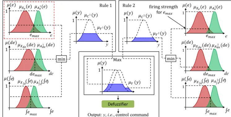
Figure 1 shows the general structure of a FLC [28], which includes three parts: (1) fuzzifier part (red block); (2) inference engine part (blue block): it combines fuzzified inputs with IF-THEN rules using a t-norm to derive the firing strength for each rule from the rule base (purple block); and (3) defuzzifier part (green block). The inference engine and defuzzifier parts are the same in both NSFLCs and SFLCs. However, the difference between SFLCs and NSFLCs is the handling of the crisp inputs in the fuzzifier part.
1) Singleton FLC: For the SFLC, its singleton fuzzifier maps a crisp inputxinto a fuzzy setX with supportx0, i.e.,:
µX(x) = (
1, x=x0
Fig. 1: Overview of the FLC structure.
Remark 1: The fuzzifier of the SFLC does not model input uncertainty. To better cope with noisy, imprecise input measurements, this work employs a non-singleton fuzzifier.
2) Non-Singleton FLC: For the NSFLC, its non-singleton fuzzifier, in our work, maps a crisp input xinto a Gaussian membership function, as shown in Fig. 1:
µX(x) = exp "
−(x−x0)2
2σ2
F #
, (2)
whereσF is the spread.
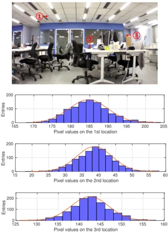
Remark 2: The non-singleton fuzzifier used here implies that the given input value x0 is the most likely value to be correct one from all the values in its immediate neighborhood. The Gaussian function is selected for the non-singleton fuzzi-fier in our work due to the measurement results from practical experiments. Fig. 2 shows the example related to the pixel value changes over time on the fixed locations of the image frame.
B. Tra-NSFLC for Navigation of Real Quadrotor UAVs
In Fig. 3, the mapping between the inputs and output of the Tra-NSFLC is illustrated. Taking thex-position controller (shown in Fig. 5) for example, it has three different inputs: position errore, the integral of errorRe, i.e., accumulated past error, and the derivative of errorde, i.e., predicted future error. Each input is fuzzified as a fuzzy set (FS) by the fuzzifier (red block in Fig. 1). The fuzzified result is shown in Fig. 3 as the red Gaussian distribution. The maximum of the intersection of the input and antecedent FSs is utilized to calculate the firing strength. Assume that the Tra-NSFLC contains only two rules, i.e.,
IF eisA1
e ANDdeisA1deAND R
eisA1
R
e THENy isC
1,
IF eisA2e ANDdeisA2deAND R
eisA2R
e THENy isC
2.
Each rule has specified an AND relationship between the mappings of the three input variables, the minimum of the three is used as the combined firing strength of each rule. Then the output of each rule is the consequent FS at the aforementioned combined firing level. For the two rules, the maximum of both output FSs is used as the output FS Y.
①
② ③
Pixel values on the 1st location
165 170 175 180 185 190 195 200 205
Entries
0 100 200
Pixel values on the 2nd location
15 20 25 30 35 40 45 50 55 60
Entries
0 100 200
Pixel values on the 3rd location
125 130 135 140 145 150 155 160
Entries
0 100 200
Fig. 2: Pixel value variation on the image frame over time which shows the uncertainty in the image information.
Finally, the output FS Y is defuzzified, the defuzzification result is the output of the NSFLC, i.e, control commandφ∗ .
The input-output mapping is represented by:
µY(y) = max[µY1(y), µY2(y)] (3)
where,
µY1(y) = min[µC1(y), min[µ1e, µ1de, µ1R e]],
µ1e= max[µXe(e)? µA1e(e)],
µ1de= max[µXde(de)? µA1 de(de)],
µ1R
e= max[µXR
e( Z
e)? µA1
R
e( Z
e)],
whereµX∗(∗)? µA1∗(∗)is the intersection of X∗ andA 1
∗. For
µY2(y), the equations are similar.
C. Input Uncertainty Sensitivity Enhanced NSFLC (Cen-NSFLC)
As introduced in subsection II-B, for Tra-NSFLCs, the calculation of the firing strength is taking the maximum of the intersection of the input FS and antecedent FS, as shown in the red dashed rectangle of Fig. 3. Figure 4 shows two different input FSs, i.e. Xe1 and Xe2, which are intersected with an antecedent A1e. Although the actual input FSs are different, the firing levels calculated by the Tra-NSFLC are the same in both cases, i.e., µX1
Fig. 3: The general mapping between the inputs and output of the Tra-NSFLC for the navigation of a real quadrotor UAV.
Thus, two different inputs or more specifically, inputs with a different associated uncertainty distribution has result in the same firing level, thereby obtaining the same output from the Tra-NSFLC. In [20], [21], the centroid of the intersection of an input and an antecedent is introduced to enhance the input uncertainty capture capability for the NSFLSs, i.e., Cen-NSFLSs. It is demonstrated for time-series prediction problems with promising results. In this work, a Cen-NSFLC is used to address real-world uncertainty affecting the control inputs of the real quadrotor UAV.
Given a discrete FS Xe1 with a membership function
µX1
e(ei), the Centroid of X
1
e is defined as below:
xcen(Xe1) = Pn
i=1eiµX1 e(ei) Pn
i=1µX1 e(ei)
, (4)
Fig. 4: Intersection of different input fuzzy sets X1
e and Xe2 with the same antecedent fuzzy set A1
e. a, b and c point locations are different firing strengths. (Adapted from [20], [21])
wherenis the number of discretization levels (n=100 in our work) utilized in a discrete system.
The centroid of the intersection of an input X∗ and an
antecedentA1∗, i.e. centroid ofX∗∩A1∗, the new input-output
mapping is:
µY(y) = max[µY1(y), µY2(y)] (5)
where,
µY1(y) = min[µC1(y), min[µ1e, µ1de, µ1R e]],
µ1e=µXe∩A1e(xcen(Xe∩A
1
e)),
µ1de=µXde∩A1
de(xcen(Xde∩A
1
de)),
µ1Re=µXR
e∩A1R
e(xcen(X R
e∩A
1
Re)).
ForµY2(y), the equations are similar. The above formulas rep-resent that the firing level of an antecedent is its membership degree at the centroid of the intersection with the input set.
III. QUADROTORUAV DYNAMICS ANDCONTROL
SCHEME
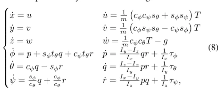
A. Quadrotor Dynamics
For describing the rigid body dynamics of the quadrotor UAV, two coordinate systems are employed: the inertial refer-ence frameFI ={~xI, ~yI, ~zI}and body-fixed reference frame FB ={~xB, ~yB, ~zB}. The origin of the body reference frame is located at the center of mass of the quadrotor UAV. The axes ~xB and~yB lie in the plane defined by the centers of the four rotors and respectively point toward the right and forward of the quadrotor UAV, as shown in the red dashed rectangle of Fig. 5.
The control of translational and rotational motions of the quadrotor UAV are achieved by changing the thrust of each rotorfi,i= 1, . . . ,4, in various combinations. The thrust from an individual rotor is varied by changing its angular speedωi,
i= 1, . . . ,4. Then, the control vectorcof the quadrotor UAV is considered as follows:
c=
T τφ τθ τψ T
, (6)
whereTis the total thrust,τφ,τθandτψare externally applied moments known as rolling, pitching and yawing moments, respectively. Under these considerations, the relation between candωi becomes [29]:
T =b ω2
1+ω22+ω23+ω24
τφ =
√
2 2 bl ω
2
1+ω22−ω32−ω24
τθ =
√
2 2 bl −ω
2
1+ω22−ω23+ω42
τψ =d −ω12+ω22+ω23−ω24
,
(7)
where b is the propeller thrust coefficient, d is the propeller drag coefficient andl is the arm length of the quadrotor UAV. The absolute position of a quadrotor UAV is described by the three Cartesian coordinates (x, y and z) of its center of mass in the inertial reference frame and its attitude by the three Euler angles (φ, θ andψ). These three angles are respectively called roll, pitch, and yaw. The time derivative of the quadrotor UAV position (x, y, z) gives the absolute velocity of the quadrotor UAV’s center of mass expressed in FI, i.e.,v=
˙
x y˙ z˙T =u v wT. Similarly, the time
derivative of the attitude provides the angular velocity inFI,
i.e.,ω=hφ˙ θ˙ ψ˙
iT .ωB =
p q rT
is the body angular rates. The quadrotor dynamical model is given below:
˙
x=u u˙ =m1 cφcψsθ+sφsψ
T
˙
y=v v˙ =m1 cφsψsθ−cψsφ
T
˙
z=w w˙ = m1cφcθT−g ˙
φ=p+sφtθq+cφtθr p˙= Iy−Iz
Ix qr+
1
Ixτφ ˙
θ=cφq−sφr q˙= IzI−Ix
y pr+
1
Iyτθ ˙
ψ=sφ cθq+
cφ
cθr r˙=
Ix−Iy Iz pq+
1
Izτψ,
(8)
where c∗, s∗ and t∗ denote cos∗, sin∗ and tan∗, m is the
quadrotor mass,gis the gravity acceleration (g= 9.81m/s2), Ix,Iy, andIz are moments of inertia, respectively.
Remark 4: The aforementioned quadrotor dynamic equa-tions are coupled, nonlinear and the system to be controlled is underactuated. In addition, the input uncertainty, e.g., noise on the camera and inertial measurement unit (IMU), in vision-based control of UAV is an inevitable problem. All these features have motivated us to use a fuzzy logic controller, instead of a model-based linear controller, which is able to handle nonlinear systems with uncertainties.
B. Control Scheme
The overall structure of the closed-loop control of the quadrotor UAV is illustrated in Fig. 5. It mainly consists of three modules, i.e., the quadrotor UAV platform (Parrot AR.DRONE 2.0 Elite Edition, equipped with a front-looking monocular RGB camera, a axis accelerometer and a 3-axis gyroscope. The quadrotor UAV publishes captured im-age frames at 30Hz with a resolution of 640×360 pixels, gyroscope measurements and the estimated horizontal velocity at 200 Hz), monocular keyframe-based visual-inertial SLAM module, and position controller.
Letp∗= [x∗, y∗, z∗, ψ∗]be the desired position defined by the end user, ˆp= [ˆx,y,ˆ z,ˆ ψˆ] is the estimated position from the keyframe-based visual-inertial SLAM algorithm during the quadrotor UAV flight, the position errorep=p∗−ˆp= [x∗− ˆ
x, y∗−y, zˆ ∗−z, ψˆ ∗−ψˆ]. The position controller computes
the desired control command u = [φ , θ , vz, vψ] for the quadrotor UAVs in order to reach the desired position p∗.
Remark 5: The roll angle, pitch angle, vertical velocity and yaw rotational speed in the desired control command are normalized to [−1,1], i.e.,φ∗, θ∗, vz∗, vψ∗ ∈[−1,1].
IV. MONOCULARKEYFRAME-BASEDVISUAL-INERTIAL
SLAM
Recently, monocular keyframe-based visual simultaneous localization and mapping (SLAM) has become a key tech-nology for different types of robots, especially for the UAVs, to estimate their positions. In the literature, the most represen-tative monocular keyframe-based SLAM approach is feature-based parallel tracking and mapping (PTAM) [30]. It is the first work to present the idea of splitting visual tracking and mapping into parallel threads. It has been demonstrated to be successful in different real-time applications. In our work, an efficient local geometric filter [9], which effectively handles outlier feature correspondences based on a forward-backward pairwise dissimilarity measure E, is used to improve the visual feature tracking thread. TheE for every pair of feature correspondences, i.e.,ci
k=(xik−1,xik) andc j k=(x
j k−1,x
j k),i6=j, is defined as below:
E(cik, cjk) =1 2 h
E(cik, cjk|Hk) +E(cik, c j k|H
−1
k ) i
, (9)
where,
E(cik, cjk|Hk) = (x
i k−x
j
k)−Hk(xik−1−x
j k−1)
,
E(cik, cjk|Hk−1) = (x
i k−1−x
j
k−1)−H
−1
k (x i k−x
j k)
.
wherek∗k is the Euclidean distance, xi
k is the ith feature location on thekth image frame.Hkis a homography transfor-mation [31], estimated by the feature correspondences between image frame Ik−1 andIk, and Hk−1 is the inversion of this homography transformation. Then a hierarchical agglomera-tive clustering approach [32] is utilized to filter out outlier correspondences based on an effective single-link approach with the forward-backward pairwise dissimilarity measureE, thereby reducing the ambiguity correspondences and filter the erroneous correspondences. Figure 6 shows some onboard captured images with feature (green point) tracking results.
The SLAM algorithm used in this study belongs to the feature-based SLAM approach. In practice, the visual SLAM algorithm highly depends on feature tracking performance. Specifically, inaccurate and uncertain position estimations will be generated under the condition of larger illumination changes, faster rotations and translations, and fewer feature detection. Moreover, monocular vision cannot determine the real scale of the environment and camera motion alone, which is essential in robot control. In this work, the onboard inertial measurement unit is used as the proprioceptive device for resolving the scale ambiguity to achieve the monocular keyframe-based visual-inertial SLAM.
Remark 6: This is the first work to implement the monocular keyframe-based visual-inertial SLAM for working with the Cen-NSFLCs. All degrees-of-freedom have been controlled in real-world UAV flight experiments.
(a) (b)
(c) (d)
Fig. 6: Onboard captured images with feature (green point) tracking results during fast UAV trajectory following applica-tion. Note that different feature tracking performances due to large rotations (Fig. 6a and Fig. 6b) and fast translations (Fig. 6c and Fig. 6d).
V. REAL-WORLDUAV FLIGHTEXPERIMENTS
Real-world quadrotor UAV flight experiments are conducted and evaluated in the OptiTrack motion capture system labo-ratory at Nanyang Technological University, Singapore. The OptiTrack system can provide real-time rigid body position measurement, i.e., ground truth, in a three-dimensional space with an update rate of 240 Hz and accuracy of 0.1mm. All the controllers, i.e., conventional PID, SFLC, Tra-NSFLC, and Cen-NSFLC, are developed in C++ within ROS. To evaluate different levels of input uncertainty affecting the control inputs of the quadrotor UAV, four different types of flight experiments with different flight speeds are carried out:
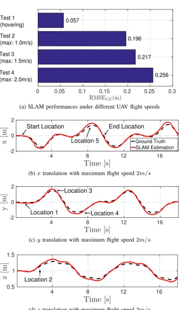
• Test1: hovering at a fixed position, the target position of quadrotor UAV is [0,0,1,0]m;
• Test 2: following a time-based 3D 080 shape trajectory with maximum flight speed 1.0m/s;
• Test 3: the same trajectory as the one in Test 2 with maximum flight speed1.5m/s;
• Test 4: the same trajectory as the one in Test 2 with maximum flight speed2.0m/s.
A. Monocular Keyframe-based Visual-Inertial SLAM Perfor-mance
Since the focus of this paper is the evaluation of different levels of input uncertainty affecting the control inputs, we review the monocular keyframe-based visual-inertial SLAM (and its properties) as the key input generating technique. The relationship between the flight speed and uncertainty level is shown in Fig. 7a. To evaluate the SLAM performance, the root mean squared error (RMSE) between the ground truth (G) and the SLAM estimation (E) is used. Figure 7a shows the average SLAM performance results with different UAV flight speeds. As can be seen from Fig. 7a, the SLAM algorithm obtains the best position estimation result during the UAV hovering flight tests. As the UAV flight speed is increasing, the position estimation accuracy is decreasing. The average RMSEGEs of Tests2,3 and4 have increased0.139m, 0.16m and0.199m
compared to the UAV hovering flight tests. Figure 7a also shows that increased flight speed results in higher position input uncertainty. Similarly, experiments showed that varia-tion amount in illuminavaria-tion, rotavaria-tion and translavaria-tion speeds, reduction in detected features - are all postiviely correlated to increasing uncertainty/noise levels in the position estimation inputs. For example, the quadrotor UAV during the hovering flights always looks at the same scene, i.e., same illumination and number of detected features, without capturing the blurred image frames.
Figure 7b, 7c and 7d showsx,y andz translation estima-tions (red color) of two rounds of the trajectory following application which is controlled by the Cen-NSFLC with a maximum flight speed of 2m/s. The ground truths (black color) of thex,yandztranslations from the OptiTrack system are used for performance comparisons. As can be seen from Fig. 7b, 7c and 7d, although faster flights result in more challenging pose estimations in the monocular keyframe-based visual-inertial SLAM, the pose estimations can match the ground truths fairly well. Therefore, the SLAM estimations are accurate enough to be used as the control inputs in the long-term navigation of the real-world quadrotor UAV. Moreover, the quadrotor UAV locations labeled in Fig. 7b, 7c and 7d are also shown with external views in Fig. 8.
Remark 7: In order to elaborate the performance of the pre-sented FLCs in this paper, different levels of input uncertainty conditions have been generated due to different UAV flight speeds. Specifically, larger UAV flight speeds will result in faster rotations and translations, fewer feature detection as well as bigger illumination changes in SLAM. Due to the fact that the SLAM algorithm highly depends on the feature tracking performance, the challenging condition of faster rotations will result in inaccurate and uncertain position estimations. In other words, the higher speed for the UAV, the more uncertainties in the localization, therefore more uncertainties in the input of the presented FLCs.
B. Control Performance
The control performances of the PID, SFLC, Tra-NSFLC and Cen-NSFLC are evaluated based on the RMSE between the ground truth (G) and the reference trajectory (R), i.e.,
RMSEGE(m)
0 0.05 0.1 0.15 0.2 0.25 0.3
0.057
0.196
0.217
0.256 Test 4
(max: 2.0m/s) Test 3 (max: 1.5m/s) Test 2 (max: 1.0m/s) Test 1 (hovering)
(a) SLAM performances under different UAV flight speeds
Time [s]
4 8 12 16
x
[m
]
-2 0 2
Ground Truth SLAM Estimation
Start Location End Location
Location 5
(b)xtranslation with maximum flight speed2m/s
Time [s]
4 8 12 16
y
[m
]
-2 0 2
Location 1
Location 3
Location 4
(c)ytranslation with maximum flight speed2m/s
Time [s]
4 8 12 16
z
[m
]
0.5 1 1.5
Location 2
(d)ztranslation with maximum flight speed2m/s
Fig. 7: Monocular keyframe-based visual-inertial SLAM per-formances.
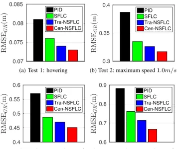
RMSEGR. Fig. 9 shows the control performance results, i.e., average RMSEGRs calculated from one hundred flight tests.
From Fig. 9, it can be observed that the Cen-NSFLC con-sistently obtains the best performance across all speed levels. The control performances of the FLCs are better than those of the conventional PID controller, while both NSFLCs can obtain superior control performance compared to the SFLC, and the Cen-NSFLC outperforms the Tra-NSFLC.
(a) Location 1. (b) Location 2. (c) Location 3. (d) Location 4. (e) Location 5.
Fig. 8: External views for the ’8’ shaped trajectory following of a quadrotor UAV for a maximum flight speed of 2m/s.
R
M
S
EG
R
(m
)
0.07 0.075 0.08 0.085
PID SFLC Tra-NSFLC Cen-NSFLC
(a) Test 1: hovering
R
M
S
EG
R
(m
)
0.3 0.35 0.4
PID SFLC Tra-NSFLC Cen-NSFLC
(b) Test 2: maximum speed1.0m/s
R
M
S
EG
R
(m
)
0.4 0.45 0.5 0.55 0.6
PID SFLC Tra-NSFLC Cen-NSFLC
(c) Test 3: maximum speed1.5m/s
R
M
S
EG
R
(m
)
0.6 0.7 0.8 0.9
PID SFLC Tra-NSFLC Cen-NSFLC
(d) Test 4: maximum speed2.0m/s
Fig. 9: Control performances of all controllers for different flight speeds.
SFLC and Tra-NSFLC. The Cen-NSFLC outperforms the PID controller during all parts of the trajectory following.
Remark 8: The main aim of this study is to elaborate input uncertainty dealing capability of different FLCs. For this goal, the following strategy is followed: It is a well-known fact that, in SLAM, different UAV flight speeds result in different inac-curate and uncertain position estimations. Therefore, different levels of uncertainties are sent to the inputs of the presented FLCs. In addition to test handling uncertainties capability in the FLC/NSFLC, several types of maneuverable flights, i.e., ascending and descending straight lines and curves, have been defined to evaluate the robustness of the controller. In real-time UAV application, in which UAV trajectories are generated online, when a PID controller is tuned with respect to curve line trajectories, it provides oscillatory responses for straight lines. On the other hand, a PID controller tuned with respect to straight line trajectories provides larger steady-state error for curve lines. We would like to emphasize that the trial-and-error approach has been used to achieve as close as to the optimal performance for all types of trajectories, i.e., straight and curve line trajectories and also for different speed values for PID controller. Unlike PID, the presented FLCs are nonlinear controllers, and they provide better performances in particular for uncertain working environments.
VI. CONCLUSIONS ANDFUTUREWORK
This study explores the real-world real-time trajectory fol-lowing problem of quadrotor UAVs under different levels of input uncertainty. A comprehensive evaluation of real UAV control performance has been conducted in the context of varying flight speeds with monocular keyframe-based visual-inertial SLAM as the primary navigation input source. Overall, four individual controllers were compared: the conventional PID controller and three different types of FLCs, i.e., a SFLC and two NSFLCs: Tra-NSFLC and the novel Cen-NSFLC, also providing the first real-world application of the Cen-NSFLC framework. The key objective of this work was not to identify the best control performance possible, but to compare the relative performance of the different controllers under different levels of input uncertainty from the real-world onboard sensors, i.e. the camera and IMU. The flight experiments conducted in this paper show that the control performances of the FLCs are better than those of the conventional PID controller, that the NSFLCs can obtain superior control performance (exhibiting better noise rejection) compared to the SFLC, and the Cen-NSFLC outperforms the Tra-NSFLC, especially at the higher flight speeds. Importantly, significant effort was made to allow for comparable levels of controller design effort for all controllers, i.e. while all controllers could be tuned further, we are confident we have been able to provide a fair basis for their comparison based on the parameters selected. It is also worth noting that the input uncertainty model employed for the NSFLCs (a Gaussian distribution associated with a crisp input) is a simplistic model which for example does not capture manufacture-published uncertainty levels of the sensors. As the best-performing Cen-NSFLC is designed to extract maximum information form the input uncertainty model, we expect that even small amounts of refinement in the input uncertainty models will result in further improved performance.
1
y [m]
0
-1 1
0
x [m]
-1 4
2
0
z
[m
]
Ref. Trajectory PID
SFLC Tra-NSFLC Cen-NSFLC
Start/End Location
(a) 3D view of trajectory following performances
y [m]
-1.5 -1 -0.5 0 0.5 1 1.5
x
[m
]
-1.5
-1
-0.5
0
0.5
1
1.5
Ref. Trajectory PID
SFLC Tra-NSFLC Cen-NSFLC Location 1
Location 3 Location 4
Location 2
Location 5
(b) X-Y 2D view of trajectory following performances
Time [s]
2 4 6 8
E
u
cl
id
ea
n
er
ro
r
[m
]
0 0.5 1 1.5
PID SFLC Tra-NSFLC Cen-NSFLC
(c) Euclidean error evolutions
Fig. 10: Trajectory following performances of all controllers in Test 4.
to explore if type-2 NSFLCs can deliver further improved performance.
ACKNOWLEDGMENT
The research was partially supported by the ST Engi-neering - NTU Corporate Lab through the NRF corporate lab@university scheme. This work was also partially funded by the RCUK’s EP/M02315X/1 From Human Data to Personal Experience grant.
REFERENCES
[1] H. Zhou, H. Kong, L. Wei, D. Creighton, and S. Nahavandi, “Efficient road detection and tracking for unmanned aerial vehicle,”IEEE Transac-tions on Intelligent Transportation Systems, vol. 16, no. 1, pp. 297–309, 2015.
[2] T. Tomic, K. Schmid, P. Lutz, A. Domel, M. Kassecker, E. Mair, I. L. Grixa, F. Ruess, M. Suppa, and D. Burschka, “Toward a fully autonomous uav: Research platform for indoor and outdoor urban search and rescue,”IEEE Robotics Automation Magazine, vol. 19, no. 3, pp. 46–56, 2012.
[3] F. Tauro, C. Pagano, P. Phamduy, S. Grimaldi, and M. Porfiri, “Large-scale particle image velocimetry from an unmanned aerial vehicle,”
IEEE/ASME Transactions on Mechatronics, vol. 20, no. 6, pp. 3269– 3275, 2015.
[4] J. Valente, D. Sanz, A. Barrientos, J. d. Cerro, A. Ribeiro, and C. Rossi, “An air-ground wireless sensor network for crop monitoring,”Sensors, vol. 11, no. 6, pp. 6088–6108, 2011.
[5] C. Fu, A. Carrio, and P. Campoy, “Efficient visual odometry and mapping for Unmanned Aerial Vehicle using ARM-based stereo vision pre-processing system,” inUnmanned Aircraft Systems (ICUAS), 2015 International Conference on, 2015, pp. 957–962.
[6] M. A. Olivares-Mendez, C. Fu, P. Ludivig, T. F. Bissyande, S. Kan-nan, M. Zurad, A. Annaiyan, H. Voos, and P. Campoy, “Towards an Autonomous Vision-Based Unmanned Aerial System against Wildlife Poachers,”Sensors, vol. 15, no. 12, pp. 31 362–31 391, 2015. [7] C. E. Doyle, J. J. Bird, T. A. Isom, J. C. Kallman, D. F. Bareiss, D. J.
Dunlop, R. J. King, J. J. Abbott, and M. A. Minor, “An avian-inspired passive mechanism for quadrotor perching,”IEEE/ASME Transactions on Mechatronics, vol. 18, no. 2, pp. 506–517, 2013.
[8] L. Wallace, A. Lucieer, and C. S. Watson, “Evaluating tree detection and segmentation routines on very high resolution uav lidar data,”IEEE Transactions on Geoscience and Remote Sensing, vol. 52, no. 12, pp. 7619–7628, 2014.
[9] C. Fu, R. Duan, D. Kircali, and E. Kayacan, “Onboard Robust Visual Tracking for UAVs Using a Reliable Global-Local Object Model,”
Sensors, vol. 16, no. 9, p. 1406, 2016.
[10] J. Pestana, I. Mellado-Bataller, J. L. Sanchez-Lopez, C. Fu, I. F. Mon-dragon, and P. Campoy, “A General Purpose Configurable Controller for Indoors and Outdoors GPS-Denied Navigation for Multirotor Unmanned Aerial Vehicles,”Journal of Intelligent & Robotic Systems, vol. 73, no. 1-4, pp. 387–400, 2014.
[11] F. Rinaldi, S. Chiesa, and F. Quagliotti, “Linear Quadratic Control for Quadrotors UAVs Dynamics and Formation Flight,” Journal of Intelligent & Robotic Systems, vol. 70, no. 1, pp. 203–220, 2012. [12] F. Chen, R. Jiang, K. Zhang, B. Jiang, and G. Tao, “Robust
Backstep-ping Sliding-Mode Control and Observer-Based Fault Estimation for a Quadrotor UAV,”IEEE Transactions on Industrial Electronics, vol. 63, no. 8, pp. 5044–5056, 2016.
[13] M. Santos, V. Lopez, and F. Morata, “Intelligent fuzzy controller of a quadrotor,” in 2010 IEEE International Conference on Intelligent Systems and Knowledge Engineering, 2010, pp. 141–146.
[14] B. Erginer and E. Altu˘g, “Design and implementation of a hybrid fuzzy logic controller for a quadrotor VTOL vehicle,” International Journal of Control, Automation and Systems, vol. 10, no. 1, pp. 61–70, 2012. [15] M. Olivares-Mendez, C. Fu, S. Kannan, H. Voos, and P. Campoy, “Using
the Cross-Entropy method for control optimization: A case study of see-and-avoid on unmanned aerial vehicles,” inControl and Automation (MED), 2014 22nd Mediterranean Conference of, 2014, pp. 1183–1189. [16] C. Fu, M. A. Olivares-Mendez, R. Suarez-Fernandez, and P. Campoy, “Monocular Visual-Inertial SLAM-Based Collision Avoidance Strategy for Fail-Safe UAV Using Fuzzy Logic Controllers,”Journal of Intelligent & Robotic Systems, vol. 73, no. 1-4, pp. 513–533, 2014.
[17] A. Cara, I. Rojas, H. Pomares, C. Wagner, and H. Hagras, “On com-paring non-singleton type-1 and singleton type-2 fuzzy controllers for a nonlinear servo system,” inAdvances in Type-2 Fuzzy Logic Systems (T2FUZZ), 2011 IEEE Symposium on, 2011, pp. 126–133.
[18] G. Mouzouris and J. Mendel, “Dynamic non-singleton fuzzy logic systems for nonlinear modeling,”Fuzzy Systems, IEEE Transactions on, vol. 5, no. 2, pp. 199–208, 1997.
[20] A. Pourabdollah, C. Wagner, and J. Aladi, “Changes under the hood - a new type of non-singleton fuzzy logic system,” inFuzzy Systems (FUZZ-IEEE), 2015 IEEE International Conference on, 2015, pp. 1–8. [21] A. Pourabdollah, C. Wagner, J. Aladi, and J. Garibaldi, “Improved Un-certainty Capture for Non-Singleton Fuzzy Systems,”IEEE Transactions on Fuzzy Systems, no. 99, pp. 1–12, 2016.
[22] D. Zhou and M. Schwager, “Assistive collision avoidance for quadro-tor swarm teleoperation,” in 2016 IEEE International Conference on Robotics and Automation (ICRA), 2016, pp. 1249–1254.
[23] T. Puls, M. Kemper, R. Kke, and A. Hein, “GPS-based position control and waypoint navigation system for quadrocopters,” in2009 IEEE/RSJ International Conference on Intelligent Robots and Systems, 2009, pp. 3374–3379.
[24] I. Dryanovski, R. G. Valenti, and J. Xiao, “An open-source navigation system for micro aerial vehicles,”Autonomous Robots, vol. 34, no. 3, pp. 177–188, 2013.
[25] N. Michael, S. Shen, K. Mohta, Y. Mulgaonkar, V. Kumar, K. Nagatani, Y. Okada, S. Kiribayashi, K. Otake, K. Yoshida, K. Ohno, E. Takeuchi, and S. Tadokoro, “Collaborative mapping of an earthquake-damaged building via ground and aerial robots,”Journal of Field Robotics, vol. 29, no. 5, pp. 832–841, 2012.
[26] S. Shen, Y. Mulgaonkar, N. Michael, V. Kumar, S. Shen, Y. Mulgaonkar, N. Michael, and V. Kumar, “Vision-Based State Estimation and Trajec-tory Control Towards High-Speed Flight with a Quadrotor,” inRobotics: Science and Systems, 2013.
[27] S. Weiss, D. Scaramuzza, and R. Siegwart, “Monocular-SLAM-based Navigation for Autonomous Micro Helicopters in GPS-denied Environ-ments,”Journal of Field Robotics, vol. 28, no. 6, pp. 854–874, 2011. [28] J. Mendel, Uncertain rule-based fuzzy logic system: introduction and
new directions. Upper Saddle River, NJ, USA, Prentice-Hall, 2001. [29] R. Mahony, V. Kumar, and P. Corke, “Multirotor Aerial Vehicles:
Modeling, Estimation, and Control of Quadrotor,”Robotics Automation Magazine, IEEE, vol. 19, no. 3, pp. 20–32, 2012.
[30] G. Klein and D. Murray, “Parallel Tracking and Mapping for Small AR Workspaces,” in6th IEEE and ACM International Symposium on Mixed and Augmented Reality, 2007, pp. 1–10.
[31] R. I. Hartley and A. Zisserman,Multiple View Geometry in Computer Vision, 2nd ed. Cambridge University Press, 2004.
[32] D. Mullner, “fastcluster: Fast Hierarchical, Agglomerative Clustering Routines for R and Python,”Journal of Statistical Software, vol. 53, no. 9, pp. 1–18, 2013.
[33] D. Mellinger and V. Kumar, “Minimum snap trajectory generation and control for quadrotors,” inRobotics and Automation (ICRA), 2011 IEEE International Conference on, 2011, pp. 2520–2525.
[34] E. Kayacan and R. Maslim, “Type-2 fuzzy logic trajectory tracking control of quadrotor vtol aircraft with elliptic membership functions,”
IEEE/ASME Transactions on Mechatronics, vol. 22, no. 1, pp. 339–348, Feb 2017.
Changhong Fu was born in Hunan, China, on July 31, 1986. He received his Ph.D. degree in Robotics and Automation from Technical University of Madrid, Spain. During his Ph.D., he held two re-search positions at Arizona State University (ASU), USA and Nanyang Technological University (NTU), Singapore. After finishing his Ph.D., he worked as a Post-Doctoral Research Fellow in Nanyang Tech-nological University at the school of Mechanical & Aerospace Engineering. Currently, he is pursuing his research in Tongji University as assistant professor.
Andriy Sarabakha was born in Lviv, Ukraine, on November 16, 1986. He received a B.Sc. degree in Computer Engineering in 2012 from ”Sapienza” -University of Rome, Rome, Italy, as well as a M.Sc. degree in Artificial Intelligence and Robotics in 2015 from the same university. From January 2016, he is pursuing his research in Nanyang Technological University, Singapore, at the School of Mechanical and Aerospace Engineering as Ph.D. student. His re-search areas are unmanned aerial vehicles, artificial intelligence and fuzzy logic.
Erdal Kayacanholds a PhD in Electrical and Elec-tronic Engineering from Bogazici University (2011). He was a visiting scholar in University of Oslo in 2009 with the research fellowship of Norway Research Council. After his post-doctoral research in KU Leuven at the Division of Mechatronics, Biostatistics and Sensors, Dr. Kayacan went on to pursue his research in Nanyang Technological Uni-versity at the School of Mechanical and Aerospace Engineering as assistant professor (2014 - current).
Christian Wagner is an Associate Professor in Computer Science at the University of Nottingham, UK and a Visiting Professor in Cybersystems at Michigan Technological University, USA. His re-search focuses on modelling and handling of uncer-tain data arising from heterogeneous data sources with a particular focus on experts and other stake-holders for application in decision support systems and data-driven policy design. He is an Associate Editor of the IEEE Transactions on Fuzzy Systems journal, Chair of the IEEE CIS Technical Committee on Fuzzy Systems and Task Force on Cyber Security; as well as elected member-at-large of the IEEE Computational Intelligence Society (CIS) Ad-ministrative Committee for 2018-2010.
Robert Johnjoined the School of Computer Science at University of Nottingham in 2013 as the Head of the Automated Scheduling, Optimisation and Plan-ning Group (ASAP) and a member of the Lab for Uncertainty in Data and Decision Making (LUCID). Prior to joining ASAP he worked for 24 years at De Montfort University as a Professor, leading a research group in Computational Intelligence as well as holding various senior management roles. Before being an academic he had a career in industry working for British Gas and software companies in Artificial Intelligence.